GeoVision GV-Compact DVR V2 User Manual
Hide thumbs
Also See for GV-Compact DVR V2:
- User manual (157 pages) ,
- Quick start manual (31 pages) ,
- How-to (4 pages)

Related Manuals for GeoVision GV-Compact DVR V2


Summary of Contents for GeoVision GV-Compact DVR V2
- Page 1 GV-Compact DVR V2 User's Manual User's Manual Firmware V1.07 Firmware V1.07 Before attempting to connect or operate this product, CDVR2V107-A please read these instructions carefully and save this manual for future use.
- Page 2 GeoVision. Every effort has been made to ensure that the information in this manual is accurate. GeoVision, Inc. makes no expressed or implied warranty of any kind and assumes no responsibility for errors or omissions. No liability is assumed for incidental or consequential damages arising from the use of the information or products contained herein.
- Page 3 Preface Welcome to the GV-Compact DVR V2 User’s Manual. The GV-Compact DVR V2 has two models designed to meet different needs. This Manual is designed for the following models and firmware version: Models Model Name Firmware Version Standard Model GV-LX4C2 1.07...
-
Page 4: Table Of Contents
Contents Chapter 1 Introduction ............1 1.1 Features........................2 1.2 Models ........................3 1.3 Packing List......................4 1.4 Options ........................7 1.5 System Requirement .....................7 Chapter 2 Physical Description..........8 2.1 Front Panel ......................8 2.1.1 Standard Model...................8 2.1.2 Anti-Vibration Model and Anti-Vibration Model of ACC Version....9 2.2 Rear Panel ......................10 2.2.1 Standard and Anti-Vibration Models ............10 2.2.2 Anti-Vibration Model of ACC Version ............11... - Page 5 Chapter 4 OSD Menu Configurations ........31 4.1 Channel Settings ....................33 4.1.1 Channel Name ..................33 4.1.2 Video/Audio Settings.................34 4.1.3 Motion Detection ..................35 4.1.4 Motion Trigger Output Settings ..............37 4.1.5 Alarm Settings...................38 4.1.6 Camera Settings ..................38 4.1.7 PTZ Settings .....................39 4.1.8 PTZ Control....................40 4.1.9 Privacy Mask.....................41 4.2 Digital IO Settings ....................42 4.2.1 Digital Input Settings .................42...
- Page 6 4.8 Advanced......................68 4.8.1 Date and Time...................68 4.8.2 Firmware Settings ..................69 4.8.3 Storage Settings..................70 4.8.4 Display Settings ..................71 4.8.5 Spot Monitor Settings................72 4.8.6 Alert Settings.....................73 4.8.7 System Settings ..................73 4.8.8 System Log ....................74 4.8.9 Backup ......................74 Chapter 5 Remote Viewing Using A Web Browser...75 5.1 Assigning an IP Address ..................75 5.1.1 Using OSD Menu ..................75 5.1.2 Connecting with a PC................76...
- Page 7 6.2.2 PTZ Settings ...................103 6.2.3 GPS......................104 6.2.4 Buzzer .....................106 6.2.5 Spot Monitor....................107 6.3 Events & Alerts ....................108 6.3.1 E-mail ......................109 6.3.2 FTP ......................111 6.3.3 Center V2 ....................113 6.3.4 VSM ......................115 6.3.5 GV-GIS....................117 6.3.6 GV-Backup Center ..................119 6.3.7 GV-Video Gateway / Recording Server ..........121 6.3.8 ViewLog Server..................123 6.3.9 RTSP / 3GPP ..................124 6.4 Monitoring ......................125...
- Page 8 PDA ........................169 9.1.1 Installing GV-GView V2................169 9.1.2 Activating the GV-GView Function............169 9.1.3 Connecting to GV-Compact DVR V2 ............170 9.1.4 Playing Back the Recordings from GV-Compact DVR V2 ......171 9.1.5 Other Functions..................172 Windows Smartphone ..................177 9.2.1 Installing GV-MSView V2 / V3 ..............177 9.2.2...
- Page 9 Chapter 10 DVR Configurations ........191 10.1 Setting up GV-Compact DVR V2..............192 10.2 Remote Monitoring with Multi View ...............195 10.3 Remote Monitoring with E-Map ..............197 Chapter 11 CMS Configurations........199 11.1 Center V2 ......................199 11.2 VSM ........................201 11.3 Dispatch Server ....................202 Chapter 12 The I/O Terminal Block ........203 12.1 Pin Assignment....................203...
-
Page 10: Chapter 1 Introduction
The special design of the GV-Compact DVR V2 enables you to link up with TV, VGA and spot monitors simultaneously for direct display. The GV-Compact DVR V2 offers many features... -
Page 11: Features
1.1 Features • Vibration and mechanical shock protection (Anti-Vibration model) • 4-channel video and audio recording and playback • Up to 704 x 480 (NTSC) / 704 x 576 (PAL) recording resolution • Up to 120 images per second recording rate at D1 resolution •... -
Page 12: Models
• Anti-Vibration Model and Anti-Vibration Model of ACC Version (GV-LX4C2V) The GV-Compact DVR V2, equipped with vibration absorbers, can withstand severe levels of shock and vibration in mobile environments. Caution: Standard and Anti-Vibration models have different internal designs. It is forbidden to connect Standard model to the vehicle power supply. -
Page 13: Packing List
Power Adaptor 12V, 5.0A x 1 • AC Power Cord x 1 • Lock Key x 2 • GV-Compact DVR V2 Remote Control x 1 • GV-Compact DVR V2 Quick Start Guide x • GV-Compact DVR V2 Software DVD x 1 •... - Page 14 Cigarette Lighter Power Adapter x 1 • Lock Key x 2 • GV-Compact DVR V2 Remote Control x 1 • GV-Compact DVR V2 Quick Start Guide x 1 • GV-Compact DVR V2 Software DVD x 1 • GV-NVR Quick Start Guide •...
- Page 15 • • Shorting Cable x 1 Lock Key x 2 • GV-Compact DVR V2 Remote Control x 1 • GV-Compact DVR V2 Quick Start Guide x • GV- Compact DVR V2 Software DVD x 1 • GV-NVR Quick Start Guide •...
-
Page 16: Options
Model of ACC Version to test the connection. 1.5 System Requirement To access the Web interface of the GV-Compact DVR V2, it is required to use Microsoft Internet Explorer 7.x or later. Note: If you are using Microsoft Internet Explorer 8, additional settings are required. See... -
Page 17: Chapter 2 Physical Description
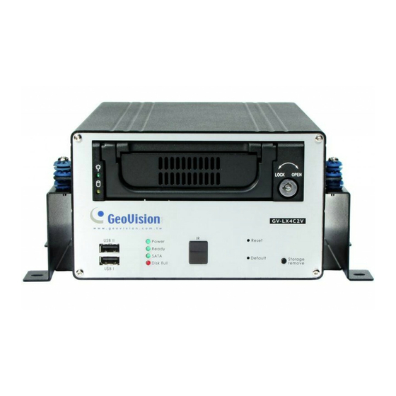
Chapter 2 Physical Description This section identifies the various components of the GV-Compact DVR V2, and provides the overview of the remote control. 2.1 Front Panel 2.1.1 Standard Model Figure 2-1 Description No. Name The two USB ports can connect the USB storage device, USB Port Wireless LAN adaptor and/or mobile Internet device. -
Page 18: Anti-Vibration Model And Anti-Vibration Model Of Acc Version
Physical Description 2.1.2 Anti-Vibration Model and Anti-Vibration Model of ACC Version Figure 2-2 Description No. Name The two USB ports can connect the USB storage device, USB Port Wireless LAN adaptor and/or mobile Internet device. • Power LED: Turns on when the power is supplied. •... -
Page 19: Rear Panel
2.2 Rear Panel 2.2.1 Standard and Anti-Vibration Models Figure 2-3 No. Name Description Connects to power supply. DC Power Input (12V) Connects to the optional External IR Receiver. External IR Receiver Port When using the Loop function, turn the switches to OFF 75 Ω... -
Page 20: Anti-Vibration Model Of Acc Version
Physical Description 2.2.2 Anti-Vibration Model of ACC Version Figure 2-4 Description No. Name Connects to power supply. DC Power Input (12V) Connects to the optional External IR Receiver. External IR Receiver Port When using the Loop function, turn the switches to OFF 75 Ω... -
Page 21: Remote Control
2.3 Remote Control The GV-Compact DVR V2 Remote Control is provided to configure and operate the GV-Compact DVR V2. Figure 2-5 Button Description Stops recording. Starts recording. OSD menu: Moves the focus upward to the desired item. Playback: Decreases the speed of playback. -
Page 22: Physical Description
Calls up the main menu. Quits the menu selection or exits the menu. Switches among up to 3 units of GV-Compact DVR V2 for remote control. To A / B / C set the device type of the GV-Compact DVR V2, see IR TYPE, 4.8.4 Display Device Type Settings. -
Page 23: Chapter 3 Getting Started
Chapter 3 Getting Started Getting started with the GV-Compact DVR V2 consists of the following steps: 3.1 Basic Connection Install the video display devices. 3.2 Connecting Anti-Vibration Model Connect the unit to the vehicle. 3.3 Connecting Anti-Vibration Model of ACC Version Connect the unit to the vehicle. -
Page 24: Basic Connection
1. To set the video resolution on the VGA monitor, see VGA SETTINGS, 4.8.4 Display Settings. 2. The GV-Compact DVR V2 cannot work with the microphone that acquires power from the unit. Use the microphone that has external power supply. -
Page 25: Connecting Anti-Vibration Model
It is easy to connect the Anti-Vibration model to a vehicle. Using the supplied Cigarette Lighter Power Adaptor, connect one end to the DC power input on the GV-Compact DVR V2 and the other end to a car‘s cigarette lighter socket. The car battery will supply power to the unit. -
Page 26: Connecting Anti-Vibration Model Of Acc Version
2. Power on the unit by using a power adaptor. The unit automatically starts after powering up for 5 seconds. 3. Set up the settings of the GV-Compact DVR V2, such as storage, images, recording and etc through its OSD or Web interface. See 3.7 Formatting Hard Drive and 3.9 Basic Operation. -
Page 27: Connecting To The Vehicle
3.3.2 Connecting to the Vehicle You need to connect the Anti-Vibration Model of ACC Version to ACC wire and power wire on the vehicle. When the unit is connected to the ACC wire properly, it will automatically start after you power on the vehicle for 5 seconds. After you power off the vehicle for 30 seconds, the unit will turn off automatically. -
Page 28: Getting Started
Getting Started Connecting the ACC Wire 1. Locate the fuse box. The fuse box is usually located below the dashboard and to the left of the steering wheel. You may need to refer to the owner’s manual of your vehicle. Figure 3-5 2. - Page 29 4. Locate the ACC wire connected to the cigarette lighter fuse and connect it to Pin 16 of the Terminal Block on the GV-Compact DVR V2. Figure 3-8 Connecting the Power Wire The supplied power cable of the Anti-Vibration model splits into two wires. Connect the white wire to the vehicle’s power cable and use the black wire to make the ground connection.
- Page 30 1. Using the fuse specification diagram, locate the power cable connecting to the fuse box and connect the white power wire of the GV-Compact DVR V2 to the positive voltage of the power cable. You may need to use a voltmeter to determine which one is the positive voltage.
- Page 31 30 seconds after the car ignition is off, try to connect the black ground wire using the other method. 4. Turn on the car ignition and the GV-Compact DVR V2 should start automatically within 5 seconds. Turn off the car ignition and the GV-Compact DVR V2 should shut down 30...
-
Page 32: Connecting Optional Video Output Devices
Getting Started 3.4 Connecting Optional Video Output Devices The GV-Compact DVR V2 offers the looping video output for 4 monitors. The GV-Compact DVR V2 also offers the spot monitor output to display video sequentially from each video input. For the settings of the spot monitor, see 4.8.5 Spot Monitor Settings. -
Page 33: Installing Hard Drive
3.5 Installing Hard Drive The GV-Compact DVR V2 comes equipped with a 3.5” SATA hard drive bay for video recording. Follow these steps to install the hard drive. 1. Make sure the unit is powered off. 2. For users of the Standard model, open the door of drive bay, push the hard drive inside, and close the door. - Page 34 Getting Started 4. For users of the 2.5” SATA hard drive, you need the optional accessory of a HDD Converter to enclose your 2.5” hard drive. Figure 3-17 • For users of the Standard model, push the Converter installed with a 2.5” hard drive back in the drive bay of the unit, and close the door.
-
Page 35: Turning On / Off The Power
If the GV-Compact DVR V2 is installed in a vehicle, the unit will automatically turn off after you power off the vehicle for 30 seconds. During the 30 seconds, the GV-Compact DVR V2 will... -
Page 36: Formatting Hard Drive
Getting Started 3.7 Formatting Hard Drive The GV-Compact DVR V2 is a Linux-based system. You must follow the steps below to format the hard drive before recording. 1. Press the Menu button on the Remote Control to enter the main menu. -
Page 37: Main Screen Overview
Figure 3-20 1. Date and time: Indicates the current date and time when viewing live video. 2. A / B / C: Indicates the type of device defined for the GV-Compact DVR V2. 3. Monitoring icon : Appears when the monitoring is activated. -
Page 38: Basic Operation
The RED recording icon will appear on the corresponding camera screen. The SATA LED and HDD Activity LED lights will be blinking, indicating the GV-Compact DVR V2 is in recording mode. •... -
Page 39: Search/Playback Operation
3.9.3 Search/Playback Operation To access the recorded video for playback, press the Search button to have several search and playback options. For details, see 4.6 Search/Playback. 3.9.4 PTZ Operation To install the PTZ camera, press the Menu button on the Remote Control, select CHANNEL SETTINGS, press one Channel button (CH1 - CH4), and then select PTZ Settings. -
Page 40: Chapter 4 Osd Menu Configurations
OSD Menu Configurations Chapter 4 OSD Menu Configurations The GV-Compact DVR V2 is configured through a series of menus on screen by using the Remote Control. This section describes the functions and options in the on-screen display (OSD) menus. To enter the main menu, press the Menu button on the Remote Control. Eight submenus will appear as shown below. - Page 41 List of Main Menu Options Find the topic of interest by referring to the section number prefixed to each option. 4.1.1 CHANNEL NAME 4.1.2 VIDEO/AUDIO SETTINGS 4.1.3 MOTION DETECTION 4.1.4 MOTION TRIGGER OUTPUT SETTINGS 4.1 CHANNEL SETTINGS 4.1.5 ALARM SETTINGS 4.1.6 CAMERA SETTINGS 4.1.7 PTZ SETTINGS 4.1.8 PTZ CONTROL...
-
Page 42: Channel Settings
OSD Menu Configurations 4.1 Channel Settings In Channel Settings, you can adjust the device settings for each channel. To set up a channel, press the Menu button on the Remote Control, select CHANNEL SETTINGS, press one Channel button, and select one of the setting options. These setting options are described in the following. -
Page 43: Video/Audio Settings
4.1.2 Video/Audio Settings You can adjust the audio and video settings for the selected channel. Select APPLY TO ALL to apply the same settings to all four channels. Figure 4-3 VIDEO RESOLUTION: Select the video resolution from 704 x 480, 704 x 240, 352 x 240, 352 x 240 3GPP v7 for NTSC format;... -
Page 44: Motion Detection
OSD Menu Configurations 4.1.3 Motion Detection Motion detection is used to generate an alarm whenever movement occurs in the video image. You can configure up to 8 areas of different sensitive values for motion detection. 1. Select MOTION DETECTION. This screen appears. The default sensitivity value is 2 for the whole area. - Page 45 5. Press the directional buttons to place the detection area, and press the button. 6. Press the directional buttons to modify the size of the detection area, and press the button. Figure 4-6 7. Select SENSITIVITY value from Low (1), Medium (2) and High (3), and press the button.
-
Page 46: Motion Trigger Output Settings
OSD Menu Configurations 4.1.4 Motion Trigger Output Settings The alarm output can be triggered simultaneously when motion is detected. To activate the output settings, you must also start monitoring manually or by schedule. See 4.4 Monitoring Settings. Figure 4-8... -
Page 47: Alarm Settings
4.1.5 Alarm Settings You can capture images before and/or after a motion and an I/O event happens. Figure 4-9 PRE-ALARM BUFFER: Activate video recording before an event occurs. Set the recording time to 1 or 2 seconds. POST-ALARM RECORDING: Activate video recording onto the hard disk after an event occurs. -
Page 48: Ptz Settings
To set up the baud rate, speed and address, consult your PTZ documentation. Figure 4-11 Note: 1. Currently the GV-Compact DVR V2 does not support the PTZ camera with RS-232 interface. 2. A total of 47 supported PTZ models are listed on the OSD. Using the Web interface, you have more options for supported PTZ models. -
Page 49: Ptz Control
4.1.8 PTZ Control After setting up the PTZ camera, you can press the Channel button on the remote Control to display the PTZ channel. Use the directional buttons to control the PTZ movement. Press the Menu button to access advanced functions. The availability of certain PTZ functions depends on different models. -
Page 50: Privacy Mask
OSD Menu Configurations 4.1.9 Privacy Mask You can set up the Privacy Mask to block out sensitive areas from view by covering the areas with black or white boxes in both live view and recorded clips. This function is only available for firmware version 1.06. -
Page 51: Digital Io Settings
GPS. 4.2.1 Digital Input Settings The GV-Compact DVR V2 can connect up to 4 input devices. To select one input device for setup, press the desired Channel button on the Remote Control. -
Page 52: Digital Output Settings
OSD Menu Configurations 4.2.2 Digital Output Settings The GV-Compact DVR V2 can connect up to 4 output devices. To select one output device for setup, press the desired Channel button on the Remote Control. Figure 4-15 STATE: Enable the selected output. -
Page 53: Gps Settings
4.2.3 GPS Settings The GV-Compact DVR V2 supports the Global Position System (GPS) for active vehicle tracking and location verification. The vehicle location will be tracked on Google maps. Figure 4-16 STATE: Enable the GPS function. BAUD RATE: Two baud rate options are available: 4800 and 9600. By default the value is 9600. -
Page 54: Events And Alerts
Note: The Motion Detection function is an optional setting since it is activated by default. 4.3.1 E-mail After a trigger event, the GV-Compact DVR V2 can send the e-mail to a remote user containing a captured still image. Figure 4-17 STATE: Enable the e-mail function. -
Page 55: Ftp
PASSWORD: Enter a valid password to log into the FTP Server. REMOTE DIR: Enter the name of the storage folder on the FTP Server. FTP SERVER MODE: Enable the GV-Compact DVR V2 to act as a FTP Server, allowing users to download the AVI files. -
Page 56: Center V2
OSD Menu Configurations 4.3.3 Center V2 After a motion or an I/O triggered event, the central monitoring station Center V2 can get notified by live videos and text alerts. For the monitoring through Center V2, you must already have a subscriber account on Center V2. Figure 4-19 ACTIVATE LINK: Enable the monitoring through Center V2 for alert events. -
Page 57: Vsm
4.3.4 VSM After a motion or an I/O triggered event, the central monitoring station VSM can get notified by text alerts. For the monitoring through VSM, you must already have a subscriber account on VSM. Figure 4-20 ACTIVATE LINK: Enable the monitoring through VSM for alert events. HOSTNAME/IP: Enter the host name or IP address of VSM. -
Page 58: Gv-Gis
OSD Menu Configurations 4.3.5 GV-GIS Through the Internet connection, the GV-Compact DVR V2 equipped with the GPS device can send GPS data and live video to the GV-GIS (Geographic Information System) for the services of vehicle tracking, location verification and live monitoring. -
Page 59: Gv-Video Gateway
4.3.6 GV-Video Gateway / GV-Recording Server You can send the video images to the GV-Video Gateway / GV-Recording Server. Figure 4-22 Activate Link: Enable the connection to the GV-Video Gateway / GV-Recording Server. HOSTNAME/IP: Enter the host name or IP address of GV-Video Gateway / GV-Recording Server. -
Page 60: Remote Playback
OSD Menu Configurations 4.3.7 Remote Playback You can remotely access the recorded files saved at the GV-Compact DVR V2 and play video back with the ViewLog player. Select YES to activate the remote playback server built in the unit. Keep the default port 5552 or modify it if necessary. -
Page 61: 3Gpp
3GPP server, you can receive live video streaming from the GV-Compact DVR V2 by entering the IP address (domain name) and password of the GV-Compact DVR V2 on the 3G-enable mobile phone. See Chapter 9 Mobile Phone Surveillance. -
Page 62: Monitoring Settings
OSD Menu Configurations 4.4 Monitoring Settings You can start recording manually, by schedule or by input trigger. Figure 4-25 MONITORING MODE: Select MANUAL to manually start recording or I/O monitoring. If you choose this option, configure the following item CHANNEL (CH 1 – CH 4) or INPUT. Select SCHEDULE to start recording and I/O monitoring by the schedule you set up. -
Page 63: Recording Schedule
4.5 Recording Schedule The schedule is provided to activate recording and I/O monitoring on a specific time each day. 4.5.1 Specific Day The system will operate automatically on the specific days you have scheduled. Press the button on the Remote Control to start setting and then use the directional buttons to define the days. -
Page 64: Channel Schedule
OSD Menu Configurations 4.5.2 Channel Schedule You can set up different monitoring schedules for each camera. Press the Channel button on the Remote Control to select one channel for setup. Figure 4-27 Span 1- Span 3: Sets different recording modes for each time frame during the day. Each day can be divided into 3 time frames, represented by Span 1 to Span 3. -
Page 65: I/O Monitoring Schedule
4.5.3 I/O Monitoring Schedule You can set up the schedule for I/O monitoring to start. Figure 4-28 Span 1- Span 3: Set different time frames during the day to enable I/O monitoring. Each day can be divided into 3 time frames, represented by Span 1 to Span 3. Weekend: If you want to have the I/O monitoring all day during the weekend, enable this option and define whether your weekend includes Saturday and Sunday (SAT-SUN) or Only Sunday (SUN). -
Page 66: Search/Playback
OSD Menu Configurations 4.6 Search/Playback You can retrieve the recorded video by date, time and event. To access the SEARCH/PLAYBACK menu, press the Menu button or the Search button on the Remote Control. 4.6.1 Time Map List The Time Map List provides an overview of the recorded videos in the form of a calendar. 1. -
Page 67: List All
4.6.2 List All The list displays a complete list of recorded videos. To move the list screen up and down one page, press the right and left directional buttons on the Remote Control. To start playback, highlight the desired video and press the button. -
Page 68: Advanced Search
OSD Menu Configurations 4.6.7 Advanced Search You can limit your search by defining search criteria. Figure 4-31 SOURCE: Search the recorded video from the selected channel or all channels. EVENT: Select the type of recorded videos with the options of MOTION + IO, MOTION, ALL IO, IO 1, IO 2, IO 3 and IO 4. -
Page 69: Network
4.7 Network The GV-Compact DVR V2 allows you to use a Web browser to remotely view and manage the system. For remote access, configure the related network settings in this section. To assign an IP address to the Compact DVR V2, see Chapter 5 Remote Viewing Using A Web Browser. -
Page 70: Connection Settings
Before enabling WIRELESS, configure WIRELESS SETTINGS which is explained in the following section. GAIN IP: FIXED: Assign a static IP or fixed IP to the GV-Compact DVR V2. Enter the GV-Compact DVR V2’s static IP address, subnet mask, gateway, primary DNS and secondary DNS. -
Page 71: Wireless Settings
4.7.3 Wireless Settings To use the wireless function, a wireless LAN USB Adaptor is required. For supported wireless LAN adaptors, see Appendix A. Figure 4-34 NETWORK TYPE: Select AD HOC or INFRASTRUCTURE for the network mode. AD HOC: A Peer-to-Peer mode. This mode connects to other computer with the WLAN card, and does not need the Access Point to connect to each other. -
Page 72: Advanced Tcp/Ip
Figure 4-35 HOST NAME: Enter a descriptive name for the GV-Compact DVR V2. HTTP PORT: The HTTP port enables connecting the GV-Compact DVR V2 to the web. For security integration, the Administrator can hide the server from the general HTTP port by changing the default HTTP port of 80 to a different port number within the range of 1024 thru 65535. -
Page 73: Umts Settings
After a mobile broadband device (supporting UMTS, HSDPA and etc) is attached to the USB port on the GV-Compact DVR V2 and the UMTS function is enabled, the GV-Compact DVR V2 can have Internet connectivity. For the supported mobile broadband devices, see Appendix B. -
Page 74: Ddns Settings
DDNS (Dynamic Domain Name System) provides a convenient way of accessing the GV-Compact DVR V2 when using a dynamic IP. DDNS assigns a domain name to the unit, so that the Administrator does not need to go through the trouble of checking if the IP address assigned by DHCP server or ISP (in xDSL connection) has changed. -
Page 75: Multicast Settings
The multicast streams are only sent to the hosts on a local network. Figure 4-38 STATE: Enable the Multicast function. HOST NAME: Name the GV-Compact DVR V2 in a multicast group. INFO UPDATE PERIOD: Enter the time length between each update of multicast streams. -
Page 76: Web User Account Info
OSD Menu Configurations 4.7.8 Web User Account Info You can change the login name and password of Administrator, Guest and FTP Server User. • The default Administrator login name and password are admin. • The default Guest login name and password are guest. •... -
Page 77: Advanced
If you select NETWORK, then the option of SERVER appears. Use the on-screen keypad to enter the IP address of the time server. DAY LIGHT SAVING: Automatically adjust the GV-Compact DVR V2 for daylight saving time. Enter the Start and End time of daylight saving. -
Page 78: Firmware Settings
GeoVision will periodically release the updated firmware on the website. The new firmware can be simply loaded into the GV-Compact DVR V2 by using the USB storage device. For the details on upgrading the unit over the network, see Chapter 8 Advanced Applications. -
Page 79: Storage Settings
4.8.3 Storage Settings You can configure the settings of the connected hard disk drive. Figure 4-42 STORAGE STATUS: Display the total size and space usage of the hard drive. STORAGE MANAGEMENT: This option allows you to format the hard disk. For details, see 3.7 Formatting Hard Drive. -
Page 80: Display Settings
OSD Menu Configurations 4.8.4 Display Settings You can show or hide the time, date, disk space, camera information and specific cameras appearing on the screen. Figure 4-43 INFO DISPLAY SETTINGS: Show or hide the information of date and time, hard disk space, channel number and camera name on the image. -
Page 81: Spot Monitor Settings
TIME FORMAT: Select one of the four display formats. 4.8.5 Spot Monitor Settings You can configure the settings when a spot monitor is connected to the GV-Compact DVR V2. Figure 4-44 NORMAL DWELL TIME: Select the amount of time that each video remains on the spot monitor before the GV-Compact DVR V2 switches to the next video in a rotation. -
Page 82: Alert Settings
OSD Menu Configurations 4.8.6 Alert Settings The system buzzer can be activated automatically under these conditions: video lost, input device triggered, motion detected, disk full and disk write error. The duration of buzzing sounds is definable. When the buzzer starts beeping, pressing any button on the Remote Control can stop it. -
Page 83: System Log
4.8.8 System Log You can view and save the events logged on the GV-Compact DVR V2. To back up the log, connect a USB mass storage device to the unit. Then press the REC button on the Remote Control to start the backup. The performance of log backup will also be recorded in the system log. -
Page 84: Chapter 5 Remote Viewing Using A Web Browser
Remote Viewing Using a Web Browser Chapter 5 Remote Viewing Using A Web Browser Not only can the GV-Compact DVR V2 operate as a standalone, but also a networked device. Using the Internet Explorer, you can remotely access and manage the GV-Compact DVR V2. -
Page 85: Connecting With A Pc
5.1.2 Connecting with a PC Use a computer on the same LAN with the GV-Compact DVR V2 to assign the IP address. The GV-Compact DVR V2 has a default address of 192.168.0.10. The computer used to set the IP address must be under the same IP and subnet sequence assigned to the unit. -
Page 86: Remote Viewing Using A Web Browser
Remote Viewing Using a Web Browser Important: 1. If Dynamic IP Address and PPPoE are enabled, you must check the current IP address from the OSD screen of Network Status (Figure 4-31) every time before logging in the unit. Otherwise, you may enable the DDNS function that links a domain name to the unit’s changing IP address first. -
Page 87: Accessing Your Surveillance Images
Once installed, the GV-Compact DVR V2 is accessible on a network. Follow these steps to access your surveillance images: 1. Start the Internet Explorer browser. 2. Enter the IP address or the domain name of the GV-Compact DVR V2 in the Location/Address field of your browser. Figure 5-3 3. -
Page 88: Functions Featured On The Main Page
Remote Viewing Using a Web Browser 5.3 Functions Featured on the Main Page Two types of users are allowed to log in the GV-Compact DVR V2: Administrator and Guest. The Administrator has unrestricted access to all system configurations, while the Guest has the access to live view and network status only. -
Page 89: The Live View Window
5.3.1 The Live View Window In the left menu, click Live View, and then select Camera 1, Camera 2, Camera 3, Camera 4 or 4 Cameras to see the live video. 2 3 4 5 6 7 Figure 5-5 No. Name Function Play Plays live video. -
Page 90: The Control Panel Of The Live View Window
Figure 5-6 [Information] Displays the version of the GV-Compact DVR V2, local time of the local computer, host time of the GV-Compact DVR V2, and the number of users logging in to the GV-Compact DVR V2. [Video] Displays the current video codec, resolution and data rate. -
Page 91: Snapshot Of A Live Video
5.3.3 Snapshot of a Live Video To take a snapshot of live video, follow these steps: 1. Click the Snapshot button (No. 5, Figure 5-5). The Save As dialog box appears. 2. Specify Save in, type the File name, and select JPEG or BMP as Save as Type. You may also choose whether to display the name and date stamps on the image. -
Page 92: Picture-In-Picture And Picture-And-Picture View
Remote Viewing Using a Web Browser 5.3.5 Picture-in-Picture and Picture-and-Picture View The full screen mode provides two types of close-up views: Picture-in-Picture (PIP) and Picture-and Picture (PAP). The two views are useful to provide clear and detailed images of the surveillance area. To access this feature: •... - Page 93 Picture-and-Picture View With the Picture and Picture (PAP) view, you can create a split video effect with multiple close-up views on the image. A total of 7 close-up views can be defined. Figure 5-8 Select PAP. A row of three inset windows appears at the bottom. Draw a navigation box on the image, and this selected area is immediately reflected in one inset window.
-
Page 94: Alarm Notification
Remote Viewing Using a Web Browser 5.3.6 Alarm Notification After input triggers and motion detection, you can be alerted by a pop-up live video and view up to four captured images. Pop-up live video Captured images Figure 5-9 To configure this function, click the Show System Menu button (No. 11, Figure 5-5), and select Alarm Notify. -
Page 95: Video And Audio Configuration
5.3.7 Video and Audio Configuration You can enable the microphone and speaker for two-way audio communication and adjust the audio volume. To change audio configuration, click the Show System Menu button (No. 11, Figure 5-5), and select Video and Audio Configuration. Figure 5-11 5.3.8 Remote Configuration You can view the connection status of the central monitoring stations and upgrade firmware... -
Page 96: Image Enhancement
Remote Viewing Using a Web Browser 5.3.10 Image Enhancement To enhance the image quality of live video, click the Show System Menu button (No. 11, Figure 5-5), and select Image Enhance. This dialog box appears. Figure 5-12 De-Interlace: Coverts the interlaced video into non-interlaced video. De-Block: Removes the block-like artifacts from low-quality and highly compressed video. -
Page 97: Visual Ptz
5.3.12 Visual PTZ In additional to the PTZ control panel, you can display a visual PTZ control panel on the image. This feature is only available when the PTZ is set ahead by the Administrator. For details, see 6.2.2 PTZ Settings. Figure 5-14 To access this feature, click the PTZ Control button (No. -
Page 98: I/O Control
Remote Viewing Using a Web Browser 5.3.13 I/O Control The I/O Control window provides real-time graphic displays of camera and I/O status, and alarm events. Additionally, you can force output to be triggered. Figure 5-15 To display the I/O control window, click the I/O Control button (No. 8, Figure 5-5). The Alarm List is displayed in three levels. -
Page 99: Visual Automation
5.3.14 Visual Automation The Visual Automation allows you to change the current state of the electronic device by simply clicking on its image, e.g. turning the light ON. This feature is only available when the Visual Automation is set ahead by the Administrator. For details, see 6.1.4 Visual Automation. Figure 5-16 To access this feature, click the I/O Control button (No. -
Page 100: Chapter 6 Remote Configurations
Remote Configurations Chapter 6 Remote Configurations The Administrator can remotely configure the GV-Compact DVR V2 via the Internet. Eight categories of configurations are involved in the system configuration: Video and Motion, Digital I/O and PTZ, Events and Alerts, Monitoring, Recording Schedule, Remote ViewLog, Network, and Management. - Page 101 List of Menu Options Find the topic of interest by referring to the section number prefixed to each option. 6.1.1 Video Settings 6.1.2 Motion Detection 6.1.3 Text Overlay 6.1 Video and Motion 6.1.4 Visual Automation 6.1.5 VGA Output Settings 6.1.6 Video Channel Source Settings 6.2.1 I/O Control 6.2.2 PTZ Settings 6.2 Digital I/O and PTZ...
-
Page 102: Video & Motion
Remote Configurations 6.1 Video & Motion This section includes the video image settings and how the images can be managed by using Video Settings, Motion Detection, Text Overlay, Visual Automation and Video Channel Source Settings. 6.1.1 Video Settings Figure 6-2... - Page 103 [Name] Rename the camera. To display the camera name on the image, see 5.3.9 Camera Name Display. [Video Signal Type] Auto detect signal type on booting: Automatically detects the type of video input is NTSC or PAL. There are 4 options for selecting image resolutions. NTSC 704 x 480 704 x 576...
- Page 104 Remote Configurations [Record Settings] These settings are only available for the main stream. The record settings allow you to capture images before and/or after a motion and an I/O event happens. Pre-alarm recording time: Activates video recording before an event occurs. Set the recording time to 1 or 2 seconds.
-
Page 105: Motion Detection
6.1.2 Motion Detection Motion detection is used to generate an alarm whenever movement occurs in the video image. You can configure up to 8 areas with different sensitivity values for motion detection. Figure 6-3 1. The default sensitivity value is 2 for the whole area. To define a different sensitivity value, click Reset. -
Page 106: Text Overlay
Remote Configurations 6.1.3 Text Overlay The Text Overlay function allows you to type any text in any place on the camera view. Up to 16 text messages can be created. The overlaid text will also be saved in the recorded images. Figure 6-4 Select the Enable option. -
Page 107: Visual Automation
6.1.4 Visual Automation This intuitive feature helps you automate any electronic device by triggering the connected output device. When you click on the image of the electronic device, you can simply change its current state, e.g. light ON. Figure 6-6 1. -
Page 108: Vga Output Settings
Remote Configurations 6.1.5 VGA Output Settings You can select the screen resolution for the VGA output. Figure 6-8 6.1.6 Video Channel Source Settings The settings allow you to assign the video input to the desired video channel for display. Figure 6-9... -
Page 109: Digital I/O & Ptz
6.2 Digital I/O & PTZ The I/O terminal block, on the rear panel of the GV-Compact DVR V2, provides the interface for the following applications: 1. Digital Input / Relay Output 2. RS-485 interface for PTZ control 3. RS-232 interface for GPS tracking 6.2.1 I/O Control... - Page 110 Remote Configurations You can direct a PTZ camera to a preset point upon input trigger: Set PTZ camera to preset point: Enable the preset function and select the camera that maps the PTZ camera. Input on: Direct the PTZ camera to a preset point when the input is triggered. Input off: Direct the PTZ camera to another preset point when the triggered input is off.
-
Page 111: Output Setting
Output Setting The GV-Compact DVR V2 can connect up to 4 output devices, such as alarms. Select Enable to enable the output device. Choose the output signal that mostly suits the device you are using: N/O (Open Circuit), N/C (Grounded Circuit), N/O Toggle, N/C Toggle, N/O Pulse or N/C Pulse. -
Page 112: Ptz Settings
In the setting page, you may need to consult your PTZ camera’s documentation to set up its baud rate and address. For supported PTZ device list, see Appendix F. Figure 6-12 Note: Currently the GV-Compact DVR V2 does not support the PTZ camera with RS-232 interface. -
Page 113: Gps
The Maximum Save Data Size when Lost Connect: Specify the duration of GPS data to be saved in the hard disk of GV-Compact DVR V2 in case that the connection between the GV-Compact DVR V2 and GV-GIS is interrupted. When the connection is resumed,... - Page 114 Remote Configurations To display the vehicle speed: Select Overlaid with average speed on the Video Settings page, and click Apply. Video Settings page Vehicle speed in live view Figure 6-14 To track the vehicle location: See 8.3 GPS Tracking. To play back GPS tracks: If the monitoring is also activated, the GPS tracks will be recorded along with video.
-
Page 115: Buzzer
6.2.4 Buzzer The system buzzer can be activated automatically under these conditions: video lost, input device triggered, motion detected, disk full and disk write error. The duration of buzzing sounds is definable. When the buzzer starts beeping, pressing any button on the Remote Control can stop it. -
Page 116: Spot Monitor
Remote Configurations 6.2.5 Spot Monitor If the spot monitor is connected to the GV-Compact DVR V2, configure the settings of the spot monitor. Figure 6-16 Dwell time x seconds: Select the amount of time that each video remains on the spot monitor before the GV-Compact DVR V2 switches to the next video in a rotation. -
Page 117: Events & Alerts
6.3 Events & Alerts When motion is detected or I/O devices are triggered, the Administrator can set up these alert methods: 1. Send a captured still image by e-mail or FTP. 2. Notify Center Monitoring Station, Center V2, VSM or GV-GIS, by video or text alerts. To have above alert methods, you must also set the following features: •... -
Page 118: E-Mail
Remote Configurations 6.3.1 E-mail After a trigger event, the GV-Compact DVR V2 can send the e-mail to a remote user containing a captured still image. Figure 6-17 [Enable] Select to enable the e-mail function. Sever URL/IP Address: Type the URL or IP address of the SMTP server. - Page 119 Digital Input: Once the selected input is triggered, a still image will be sent to the camera assigned via e-mail. For the related settings to send e-mail alerts, see 6.1.2 Motion Detection, 6.2.1 I/O Control and 6.4 Monitoring.
-
Page 120: Ftp
Remote Configurations 6.3.2 FTP You can also send the captured still image to a remote FTP server for alerts. Figure 6-18 [Upload to a FTP Server] Enable: Select to enable the FTP function. Server URL/IP Address: Type the URL address or IP address of the FTP Server. Port Number: Type the port number of the FTP Server. - Page 121 [Act as FTP Server] You can enable the GV-Compact DVR V2 to act as a FTP Server, allowing users to download the AVI files. The default download port is 21. To access the internal FTP server through a Web browser, enter the IP address or the domain name of the GV-Compact DVR V2 in your browser like this: fpt://192.168.0.10...
-
Page 122: Center V2
After a motion or an I/O triggered event, the central monitoring station Center V2 can get notified by live videos and text alerts. For the live monitoring through Center V2, you must already have a subscriber account on Center V2. The GV-Compact DVR V2 can connect up to two Center V2 servers simultaneously. - Page 123 These options you can also find on this Center V2 setting page: Cease motion detection messages from: Stops notifying Center V2 of motion detection from selected camera(s). Cease input trigger messages from: Stops notifying Center V2 of input trigger from selected input(s).
-
Page 124: Vsm
After a motion or an I/O triggered event, the central monitoring station VSM can get notified by text alerts. For the live monitoring through VSM, you must already have a subscriber account on VSM. The GV-Compact DVR V2 can connect up to two VSM simultaneously. Figure 6-20 To enable the VSM connection: 1. - Page 125 These options you can also find on this VSM setting page: Cease motion detection messages from: Stops notifying VSM of motion detection from selected camera(s). Cease input trigger messages from: Stops notifying VSM of input trigger from selected input(s). Cease video lost messages from: Stops notifying VSM of video lost from selected camera Enable schedule mode: Starts the monitoring through VSM based on the schedule you set in the Select Schedule Time section.
-
Page 126: Gv-Gis
Remote Configurations 6.3.5 GV-GIS Through the Internet connection, the GV-Compact DVR V2 equipped with the GPS device can send GPS data and live video to the GV-GIS (Geographic Information System) for the services of vehicle tracking, location verification and live monitoring. The GV-Compact DVR V2 can connect up to two GV-GIS simultaneously. - Page 127 3. Port Number: Match the communication port on GV-GIS. Or keep the default value 3356. 4. User Name: Type a valid user name to log into GV-GIS. 5. Password: Type a valid password to log into GV-GIS. 6. Click Apply. The Connection Status should display “Connected” and connected time. 7.
-
Page 128: Gv-Backup Center
6.3.6 GV-Backup Center The connection to the GV-Backup Center allows you to back up another copy of recordings and system log to the GV-Backup Center while the GV-Compact DVR V2 is saving these data to the attached hard disk. Figure 6-22 To enable the Backup Center connection: 1. - Page 129 Backup Center failure, you can configure the connection to the failover server. 1. Set Update Frequency: Once the GV-Compact DVR V2 is disconnected from the Backup Center for the specified time, the GV-Compact DVR V2 will be directed to the failover server.
-
Page 130: Gv-Video Gateway / Recording Server
Remote Configurations 6.3.7 GV-Video Gateway / Recording Server The GV-Recording Server is a video streaming server designed for large-scale video surveillance deployments. It can receive and record up to 128 channels from various IP video devices, and distribute up to 300 channels to its clients. With the GV-Recording Server, the desired frame rate can be ensured while the CPU loading and bandwidth usage of the IP video devices are significantly reduced. - Page 131 To enable the GV-Video Gateway and GV-Recording Server connection: 1. Activate Link: Enable the connection to GV-Video Gateway / GV-Video Server. 2. Host Name or IP Address: Type the host name or IP address of GV-Video Gateway / GV-Recording Server. 3.
-
Page 132: Viewlog Server
6.3.8 ViewLog Server The ViewLog Server is designed for remote playback function. This server allows you to remotely access the recorded files saved at the GV-Compact DVR V2 and play back video with the player ViewLog. Select Enable to activate the server built in the unit. Keep the default port 5552 or modify it if necessary. -
Page 133: Rtsp / 3Gpp
RTP/UDP Port: Keep the default range from 17300 to 17319, or modify it if necessary. The number of ports for use is limited to 20. Max Connection: Set the maximum number of connections to the GV-Compact DVR V2. The maximum value is 20. -
Page 134: Monitoring
Remote Configurations 6.4 Monitoring You can start recording manually, by schedule or by input trigger. Figure 6-26 [Manual] Manually activates recording and I/O monitoring. Select one of the following options and then click the Start button. Select all: Manually starts recording and I/O monitoring as well. Camera 1 - Camera 4: Manually starts recording. -
Page 135: Recording Schedule
6.5 Recording Schedule The schedule is provided to activate recording and I/O monitoring on a specific time each day. 6.5.1 Recording Schedule Settings You can set up different monitoring schedules for each camera. Figure 6-27 Span 1- Span 3: Set a different recording mode for each time frame during the day. Each day can be divided into 3 time frames, represented by Span 1 to Span 3. -
Page 136: I/O Monitoring Settings
Remote Configurations 6.5.2 I/O Monitoring Settings You can set up the schedule for I/O monitoring to start. Figure 6-28 Span 1 to Span 3: Set different time frames during the day to enable I/O monitoring. Each day can be divided into 3 time frames, represented by Span 1 to Span 3. Weekend: If you want to have the I/O monitoring all day during the weekend, enable this option and define whether your weekend includes Saturday and Sunday or Only Sunday. -
Page 137: Remote Viewlog
GV-Compact DVR V2 over TCP/IP network. For the first-time user, you need to install the Remote ViewLog program from the Software CD. For remote access to the GV-Compact DVR V2, the ViewLog Server built in the unit must be enabled. See 6.3.8 ViewLog Server. -
Page 138: Network
Remote Configurations 6.7 Network The Network section includes some basic but important network configurations that enable the GV-Compact DVR V2 to be connected to a TCP/IP network. 6.7.1 LAN According to your network environment, select among Static IP, DHCP and PPPoE. - Page 139 IP address. To enable the DDNS function, see 6.7.3 Advanced TCP/IP. Static IP address: Assign a static IP or fixed IP to the GV-Compact DVR V2. Type the GV-Compact DVR V2’s TCP/IP and DNS parameters in the Configure connection parameters section.
-
Page 140: Wireless-Client Mode
Remote Configurations 6.7.2 Wireless-Client Mode To use the wireless function, a wireless LAN USB Adaptor is required. For supported wireless LAN adaptors, see Appendix A. Figure 6-30 Network type: Select the network mode Ad Hoc or Infrastructure. Infrastructure: Via the Access Point to connect to the Internet. This mode further gives wireless access to the Internet or data sharing under a previously wired environment. - Page 141 WPAPSK-TKIP and WPA2PSK-TKIP: Type WPA-PSK (Pre-Shared Key) for data encryption. WPAPSK-AES and WPA2PSK-AES: Type WPA-PSK (Pre-Shared Key) for data encryption. Note: Your encryption settings must match those used by the Access Points or wireless stations with which you want to associate.
-
Page 142: Advanced Tcp/Ip
Remote Configurations 6.7.3 Advanced TCP/IP This section introduces the advanced TCP/IP settings, including DDNS server, HTTP port, HTTPS port, streaming port and UPnP. Figure 6-31... - Page 143 2. Service Provider: Select the DDNS service provider you have registered with. 3. Host Name: Type the host name used to link to the GV-Compact DVR V2. For the users of GeoVision DDNS Server, it is unnecessary to fill the field because the system will detect the host name automatically.
- Page 144 To apply QoS to the GV-Compact DVR V2, all network routers must support QoS and QoS must be enabled on these devices. To enable the QoS on the GV-Compact DVR V2, enter a Differentiated Services Code Point (DSCP) value. This value is a field in an IP packet that enables different levels of services for the network traffic.
-
Page 145: Umts/Zigbee
After a mobile broadband device (supporting UMTS, HSDPA, etc.) is attached to the USB port on the front panel and the UMTS function is enabled, the GV-Compact DVR V2 can have Internet connectivity. For supported mobile broadband devices, see Appendix B. - Page 146 Remote Configurations [UMTS Settings] PIN number: Type the PIN number that is provided by your network operator. Access Point Name (APN): Type Access Point Name that is provided by your network operator. Username: Type a valid username to enable the UMTS service from your network operator.
-
Page 147: Multicast
The multicast streams are only sent to the hosts on a local network. This configuration page provides two settings. One is to allow the GV-Compact DVR V2 to join a multicast group. The other is to allow the GV-Compact DVR V2 to receive audio broadcasting from other hosts in a multicast group. -
Page 148: Ip Filter
Specify the IP address and port number to receive the audio broadcast. The default IP address is 224.1.1.3 and port number is 8400. 6.7.6 IP Filter The Administrator can set IP filtering to restrict access to the GV-Compact DVR V2. Figure 6-34 To enable the IP Filter function: 1. -
Page 149: Snmp Setting
6.7.7 SNMP Setting The Simple Network Management Protocol (SNMP) allows you to monitor the status of the camera through SNMP network management software. Figure 6-35 1. Select Enable SNMPv1 SNMPv2c to enable the function. 2. To enable access to Read/Write community, type a community string. This will serve as a password to allow read and write access to the camera from the SNMP software. -
Page 150: Management
Remote Configurations 6.8 Management The Management section includes the settings of data and time, storage device and user account. In addition, you can view the firmware version and execute certain system operations. 6.8.1 Date & Time Setting The date and time settings are used for date and time stamps on the image. Figure 6-36... - Page 151 [Date & Time on Device] Displays the current date and time on the GV-Compact DVR V2. [Time Zone] Sets the time zone for local settings. Select Enable Daylight Saving Time to automatically adjust the GV-Compact DVR V2 for daylight saving time. Type the Start Time and End Time to enable the function.
-
Page 152: Gps Maps Settings
API key in the Google Map API Key field. If your GV-Compact DVR V2 is equipped with a GPS device, it is not necessary to enter Default Longitude and Default Latitude, since its vehicle location will be traced by GPS. -
Page 153: Storage Settings
6.8.3 Storage Settings Based on Linux file system, the GV-Compact DVR V2 supports one hard drive and two external USB hard drives for video and audio recording. Normally the hard drive is ready for Windows OS. Therefore, you need to format the hard drive by using the following Storage Settings. - Page 154 [Partition Information] This section shows the partition details of the hard drive. To add a hard disk: 1. Install the hard drive to the GV-Compact DVR V2. 2. Click the Format button. After the format is complete, the partition information will be displayed. The maximum space for one partition is 200G.
-
Page 155: User Account
Figure 6-39 6.8.5 Log Information The Startup time log section contains every start time of the GV-Compact DVR V2. The startup time log is saved on the hard disk, so the log is only available when a hard disk is inserted to the GV-Compact DVR V2. -
Page 156: Tools
This section allows you to execute certain system operations and view the firmware version. Figure 6-41 [Host Settings] Enter a descriptive name for the GV-Compact DVR V2. [Auto Reboot Setup] Select Enable to activate automatic reboot and specify the time for reboot in the sub fields below. - Page 157 V2’s network setting again. [Reboot] Clicking the Reboot button will make the GV-Compact DVR V2 perform software reset. The Ready LED on the front panel will turn off. Wait until the Ready LED turns on and re-log in the unit.
-
Page 158: Acc Settings
[Power-off delay settings] Specify the power-off delay time from 0 to 30 minutes. For example, if you set 30 minutes, the GV-Compact DVR V2 will keep recording for 30 minutes, and then turn off after you power off the vehicle. -
Page 159: Chapter 7 Remote Recording And Playback
Chapter 7 Remote Recording and Playback The Administrator can remotely start recording to the GV-Compact DVR V2 and play back the recorded files over the TCP/IP network. 7.1 Remote Recording To remotely enable the recording function to the GV-Compact DVR V2: 1. -
Page 160: Playback Using Hard Drive
Remote Recording and Playback 7.2.1 Playback Using Hard Drive You can play back the files recorded at the GV-Compact DVR V2 by installing the hard drive to the GV-System. However, the GV-System is run on Windows system while the files recorded at GV-Compact DVR V2 is of Linux file system. -
Page 161: Playback Over Network
GV-Compact DVR V2’s Web interface. 3. When this dialog box appears, type the GV-Compact DVR V2’s IP address, login ID and password. Keep the default port 5552 or modify it if necessary. -
Page 162: Access To The Recorded Files Through Ftp Server
1. The GV-Compact DVR V2 must allow the remote access with ViewLog Server activated. See 6.3.8 ViewLog Server. 2. To remotely connect to GV-Compact DVR V2 from GV-System, click the Tools button and select Remote ViewLog Service. The Connect to Remote ViewLog Service dialog box appears. - Page 163 5. In Please Select a Map API, select a Map API. For Google Maps, you need to sign up for an API key from Google website (http://code.google.com/apis/maps/signup.html), and enter the API key in the Please enter the map authorization key or license key field. 6.
-
Page 164: Playback Of Daylight Saving Time Events
7.2.5 Playback of Daylight Saving Time Events On GV-System, you can retrieve the events recorded during the Daylight Saving Time (DST) period from GV-Compact DVR V2 for playback. You can also attach the USB mass storage device with the recorded files to GV-System for playback. -
Page 165: Chapter 8 Advanced Applications
8.1 Upgrading System Firmware GeoVision will periodically release the updated firmware on the website. The new firmware can be simply loaded into the GV-Compact DVR V2 over the Internet or by using the IP Device Utility included in the Software DVD. -
Page 166: Using The Web Interface
Advanced Applications 8.1.1 Using the Web Interface 1. In the Live View window, click the Show System Menu button (No. 11, Figure 5-5), select Remote Config, and click the Firmware Upgrade tab. This dialog box appears. Figure 8-1 2. Click the Browser button to locate the firmware file (.img) saved at your local computer. 3. -
Page 167: Using The Ip Device Utility
GV-Compact DVR V2 on the same LAN. Or click the New button and assign the IP address to locate a GV-Compact DVR V2 over the Internet. Or highlight one GV-Compact DVR V2 in the list and click the Delete button to remove it. - Page 168 Advanced Applications 5. Click the Firmware Upgrade tab. This dialog box appears. Figure 8-4 6. Click the Browse button to locate the firmware file (.img) saved at your local computer. 7. If you like to upgrade all the GV-Compact DVR V2s in the list, select Upgrade all devices.
-
Page 169: Backing Up And Restoring Settings
8.2 Backing Up and Restoring Settings With the IP Device Utility included in the Software DVD, you can back up the configurations in the GV-Compact DVR V2, and restore the backup data to the current unit or import it to another unit. -
Page 170: Restoring The Settings
Advanced Applications 8.2.2 Restoring the Settings 1. In Figure 8-3, click the Import Settings tab. This dialog box appears. Figure 8-6 2. Click the Browse button to locate the backup file (.dat). 3. Click Update Setting to start restoring. -
Page 171: Gps Tracking
8.3 GPS Tracking The GV-Compact DVR V2 supports the Global Position System (GPS) for active vehicle tracking and location verification. The vehicle location will be tracked by Google Maps. To track the location of your GV-Compact DVR V2: Connect the GV-GPS module to the GV-Compact DVR V2: Standard Model: Connect the GV-GPS module supporting RS-232 serial interface to the I/O terminal block on the rear panel of the unit. - Page 172 Advanced Applications To track the GV-Compact DVR V2 on Google Maps, click Open. A warning message appears. Figure 8-8 Right-click the warning message and select Allow Blocked Content. The map will be displayed. The icon indicates the location of your GV-Compact DVR V2. At the upper right corner you have options to view different map formats, such as Satellite and Hybrid.
-
Page 173: Restoring To Factory Default Settings
8.4 Restoring to Factory Default Settings To restore the GV-Compact DVR V2 to default settings, use the Reset and Default buttons on the front panel. For the location of the two buttons see 2.1 Front Panel. 1. Press and then release the Reset button immediately. -
Page 174: Verifying Watermark
Advanced Applications 8.5 Verifying Watermark The watermark is an encrypted and digital signature embedded in the video stream during the compression stage, protecting the video from the moment of creation. Watermarking ensures that an image is not edited or damaged after it is recorded. To enable the watermark function, see [Watermark], 6.1.1 Video Settings. -
Page 175: The Watermark Proof Window
8.5.3 The Watermark Proof Window Figure 8-10 The controls in the window: No. Name Description Open File Opens the recorded file. First Frame Goes to the first frame of the file. Play Plays the file. Previous Frame Goes to the previous frame of the file. Next Frame Goes to the next frame of the file. -
Page 176: Chapter 9 Mobile Phone Surveillance
Mobile Phone Surveillance Chapter 9 Mobile Phone Surveillance Using a PDA, Smartphone or 3G-enabled mobile phone, you can receive live video streaming from the GV-Compact DVR V2. The chart below lists the GV mobile applications supporting the GV-Compact DVR V2. Handheld... - Page 177 Note: 1. To receive the live video from the GV-Compact DVR V2, enter the TCP/IP port on your mobile phone. To play video back, enable ViewLog Server on the GV-Compact DVR V2 and enter the RPB Port on your mobile phone 2.
-
Page 178: Pda
Windows Mobile operating system. For the supported operating system version, see Chart 1. When GV-GView V2 detects the big screen panel of the mobile phone, images from the GV-Compact DVR V2 will be horizontally rotated for a better view. Resolution is set to be CIF by default. -
Page 179: Connecting To Gv-Compact Dvr V2
The login screen appears. Figure 9-3 3. Enter the IP address of your GV-Compact DVR V2, port value (default value is 10000), a username and a password. Then click OK. 4. Once the connection is established, the live image will appear. -
Page 180: Playing Back The Recordings From Gv-Compact Dvr V2
Figure 9-4 4. Enter the IP address of your GV-Compact DVR V2, port value (default value is 5552), a username and a password. Then click OK to connect. 5. Select the desired video recording from the event list for playback. -
Page 181: Other Functions
9.1.5 Other Functions In addition to live view and playback, GV-GView V2 offers these functions: viewing / controlling I/O devices, PTZ control, adjusting image quality, and starting / stopping recording. On the live view screen, click the buttons on the toolbar to have the desired functions. Figure 9-5 Button Description... -
Page 182: Mobile Phone Surveillance
Mobile Phone Surveillance Accessing I/O Devices To access the connected I/O devices, use the drop-down list to select the desired camera and click the button. The I/O module button appears on the toolbar. Figure 9-6 The numbers on the toolbar indicate the connected module. Click the desired number to access its I/O devices. - Page 183 Viewing Input-Triggered Events All input triggers are logged on the Alarm list. Click the “I” button (Figure 9-7) to view the list of trigger events. Figure 9-8 Forcing Outputs To force any connected output devices, click the “O” button (Figure 9-7) and click the desired number.
- Page 184 Mobile Phone Surveillance Controlling PTZ Cameras To control the PTZ camera, use the drop-down list to select the desired camera, and click the button on on the live view screen (Figure 9-5). Figure 9-10 Button Description Click it to return to the previous page. Use these buttons to move the PTZ camera to the left, up, down and right Click it to return to home.
- Page 185 Viewing Camera Status To view the camera status, click the button on the live view screen (Figure 9-5). Figure 9-11 This screen displays the status of camera activity. Three messages indicate the current camera status. Message Description The camera is turned on and not recording. Normal The camera is turned off.
-
Page 186: Windows Smartphone
Activating the GV-MSView V2 / V3 Function To allow remote access to the GV-Compact DVR V2, set the video resolution to 352 x 240 (3GPP V7) for NTSC, or 352 x 288 (3GPP V7) for PAL. See 4.1.2 Video/Audio Settings for OSD menu configurations, or 6.1.2 Video Settings for remote configurations. -
Page 187: Connecting To Gv-Compact Dvr V2
9.2.3 Connecting to GV-Compact DVR V2 The following operations may vary slightly for different modules. 1. Execute MSViewV2.exe or MSViewV3.exe on your smartphone. Figure 9-13 2. Click Type and then Live. Figure 9-14... - Page 188 Mobile Phone Surveillance 3. On the login screen, enter the IP address of your GV-Compact DVR V2, port value (default value is 10000), a username and a password. Then click Control and select Connect. Figure 9-15 4. Once the connection is established, the live image will appear. You can use the scroll key on your smartphone to navigate camera channels.
-
Page 189: Playing Back The Recordings From Gv-Compact Dvr V2
RPB with time. Figure 9-17 4. Enter the IP address of your GV-Compact DVR V2, port value (default value is 5552), a username and a password. Then click Select and click GV-Compact DVR to start the connection. -
Page 190: Symbian Smartphone
Activating the GV-SSView V3 Function To allow remote access to the GV-Compact DVR V2, set the video resolution to 352 x 240 3GPP v7 for NTSC, or 352 x 288 3GPP v7 for PAL. See 4.1.2 Video/Audio Settings for OSD menu configurations, or 6.1.2 Video Settings for remote configurations. -
Page 191: Connecting To Gv-Compact Dvr V2
The login screen appears. Figure 9-19 3. Enter the IP address of your GV-Compact DVR V2, port value (default value is 10000), a username and a password. Then click Options and select Connect. 4. Once the connection is established, the live image will appear. -
Page 192: Playing Back The Recordings From Gv-Compact Dvr V2
RPB With Time. Figure 9-21 4. Enter the IP address of your GV-Compact DVR V2, port value (default value is 5552), a username and a password. Then click Options and select GV-Compact DVR. 5. Select the desired video recording from the event list for playback. -
Page 193: Mobile Phone
9.4.1 Activating the 3G Mobile Phone Function To allow remote access to the GV-Compact DVR V2, you must follow these steps: 1. Set the video resolution to 352 x 240 3GPP v7 for NTSC, or 352 x 288 3GPP v7 for PAL. -
Page 194: Connecting To The Gv-Compact Dvr V2
Mobile Phone Surveillance 9.4.2 Connecting to the GV-Compact DVR V2 Open the Internet browser in the mobile phone and enter the IP address of your GV-Compact DVR V2. This login screen appears. Figure 9-24 Enter a User Name, a Password, and select 3G. Then click Submit to connect. -
Page 195: Playing Back The Recordings From Gv-Compact Dvr V2
9.4.3 Playing Back the Recordings from GV-Compact DVR V2 To play back the recordings from the GV-Compact DVR V2, follow these steps: Enable the ViewLog Server on GV-Compact DVR V2. Keep the connection port to be 5552 or modify it if necessary. See 6.3.8 ViewLog Server for details. - Page 196 Mobile Phone Surveillance [Last 10 Video Files] 1. Select this option. The event list that displays last 10 video files appears. Figure 9-28 2. Select the desired event from the list. The video will start to play. [PRB] Select this option. This screen appears. Search the desired video by date and time with the drop-down list, and click Submit.
-
Page 197: Android Smartphone
Android Market, and after installing the application on your mobile phone, the GV-AView icon will appear on the desktop. Follow the steps below to access a GV-System or a GV-IP device. Figure 9-30 9.5.1 Connecting to GV-Compact DVR V2 1. Tap the GV-AView icon on the main page. - Page 198 6. You can press the Menu button on the mobile phone and tap the Setting button see the SIM card information or tap the Address Book button to see the address book. 7. Tap the Connection button to connect to the GV-Compact DVR V2. The live view will appear. Figure 9-33...
- Page 199 8. The following function buttons are available on the bottom of the screen. Snapshot : Saves the current image in the mobile device. PTZ Control : Enables the PTZ function. A message will appear asking if you want to use Gesture Detector to control PTZ. Tap OK if you want to be able to drag across the live view screen to control the PTZ function in addition to using the PTZ control buttons on the bottom of the screen.
-
Page 200: Chapter 10 Dvr Configurations
The maximum number of streams that a GV-Compact DVR V2 allows is 20. When a camera is connected to one GV-Compact DVR V2, it takes up 1 stream. When a user connects to one GV-Compact DVR V2 via browser, it takes up 2 streams. When users operate the Camera/Audio Control on Center V2, it takes up 1 stream. -
Page 201: Setting Up Gv-Compact Dvr V2
Camera Install and click IP Camera Install. This dialog box appears. Figure 10-2 • To automatically set up a GV-Compact DVR V2, click Scan Camera to detect any GV-Compact DVR V3 devices on the same LAN. • To manually set up a GV-Compact DVR V2, click Add Camera. -
Page 202: Dvr Configurations
DVR Configurations Type the IP address, username and password of the GV-Compact DVR V2. Modify the default HTTP port if necessary. Select GeoVision from the Band drop-down list and select GeoVision Compact DVR from the Device drop-down list. This dialog box appears. - Page 203 Configuring the Compact DVR Settings After the GV-Compact DVR V2 is connected and assigned with a display position, you can configure settings such as frame rate, codec type and resolution. Right-click the GV- Compact DVR V2 on the IP Device Setup dialog box to see the following list of options:...
-
Page 204: Remote Monitoring With Multi View
10.2 Remote Monitoring with Multi View You can use the Multi View to monitor and manage the cameras and I/O devices connected to the GV-Compact DVR V2. Connecting to GV-Compact DVR V2 The Multi View program is available in the GV-System applications, and also included in the Software DVD as an independent program. - Page 205 Select Compact DVR from the Device drop-down list. Type the host name, IP address, user name and password of the GV-Compact DVR V2. Modify the default VSS port 10000 if necessary. Figure 10-7 6. Click Save to establish connection. For details on the Multi View functions, see “Multi View Viewer”, Chapter 8 Remote Viewing,...
-
Page 206: Remote Monitoring With E-Map
5. Right-click the created New Host in the Host View, and select Host Settings. This dialog box appears. Figure 10-8 6. Give the GV-Compact DVR V2 a location name, and type its IP address (or domain name). Keep the default VSS port as 10000, or modify it to match that of GV-Compact DVR V2. - Page 207 4. On the Remote E-Map window, click the Login button and select the GV-Compact DVR V2 host to access its videos and I/O devices. The valid user name and password are required to log in the GV-Compact DVR V2. For details on the Remote E-Map functions, see “The Remote E-Map Window”, Chapter 9 E-...
-
Page 208: Chapter 11 Cms Configurations
Preference Settings button, select System Configure, click the Network tab, and select Accept connections from GV-Compact DVR, Video Server & IP Cam. Keep default port 5551, or modify it to match the Center V2 port on the GV-Compact DVR V2. Figure 11-2... - Page 209 For example, the alarm is triggered for 5 minutes and you set 10 minutes, which means the total display time will be 15 minutes. For details on how to mange the received video from the GV-Compact DVR V2, see GV- CMS Series User’s manual.
-
Page 210: Vsm
Connective Port, keep the default Port 2 value of 5609, or modify it to match the VSM port on the GV-Compact DVR V2. Figure 11-5 For details on how to mange the received video from the GV-Compact DVR V2, see GV- CMS Series User’s manual. -
Page 211: Dispatch Server
Allow Video Server Login as Subscriber from Port. Keep the default port as 5551, or modify it to match the Center V2 port on the GV-Compact DVR Figure 11-7 For details on how to mange the received video from the GV-Compact DVR V2, see GV- CMS Series User’s manual. -
Page 212: Chapter 12 The I/O Terminal Block
The I/O Terminal Block Chapter 12 The I/O Terminal Block The 16-pin terminal block, located on the rear panel, provides the interface to: four digital inputs, four relay outputs, one RS-485 interface, one RS-232 interface and auxiliary power. The I/O terminal block can be used to develop applications for motion detection, PTZ control, GPS tracking or a variety of other functions. -
Page 213: Relay Output
The relay outputs on the terminal block can only drive a maximum load of 5 volts. Working in conjunction with the GV-Relay V2 module, it can drive heavier loads. Refer to the figure and table below to connect the GV-Relay V2 module to the GV-Compact DVR V2. Figure 12-2... -
Page 214: Camera Power Supply
The I/O Terminal Block 12.3 Camera Power Supply The cameras can be powered through GV-Compact DVR V2. Using the supplied Camera Power Cable, connect the black wire to Pin 10 and the green wire to Pin 11. Figure 12-3 I/O Terminal Block... -
Page 215: Specifications
Specifications Video Video Standard NTSC, PAL Video Input/Output 4 Videos In, 4 Loops Out Compression Geo MPEG4 (ASP) 30 fps/ch at D1 resolution NTSC Frame Rate 25 fps/ch at D1 resolution 704 x 480, 704 x 480 De-interlace, 352 x 240, 352 x 240 NTSC 3GPP v7 Video... - Page 216 Use a USB flash drive • Use the upgrade utility included on the Software CD • 1 SATA HDD of 2.5’’ or 3.5’’ (HDD converter required for 2.5’’ HDD from GeoVision) Storage (Optional) • 2 external USB mass storage devices •...
- Page 217 Connector Standard Anti-Vibration Anti-Vibration ACC Audio / Video Input D-Type, DB 15 connector (4 Videos In, 4 Audios In) D-Type, DB 15 connector (1 TV Out, 1 Spot Out, 1 VGA Out, 1 Audio / Video Output Audio Out, 4 Video Loops Out) Sensor Input 4 inputs on terminal block Alarm Output...
-
Page 218: Appendix
Appendix Appendix A. Supported Wireless LAN USB Adaptor Vendor Model D-Link DWA-140 (H/W version B1), DWL-G122 (version C1) EDIMAX EW-7318Ug, EW-7718Un Linksys WUSB54GC, WUSB600 (version 1) Pegatron WL-166N11 Note: Linksys WUSB54GC ver. 3 is not supported. B. Supported Mobile Broadband Device Vendor Model HUAWEI... -
Page 219: Settings For Internet Explore 8
D. The CGI Command The GV-Compact DVR V2 (firmware V1.06) supports a CGI command function for obtaining a snapshot of the live view without logging in the Web interface. For a GV-Compact DVR V2 with the the following details: IP address: 192.168.2.109... -
Page 220: Rtsp Protocol Support
GV-Compact DVR V2:8554/<CH No.>.sdp For example, rtsp://192.168.3.111:8554/CH001.sdp Note: 1. For firmware V1.06 or later, the GV-Compact DVR V2 can support RTSP protocol for both video and audio streaming; for firmware V1.05, only the video streaming is supported. -
Page 221: Supported Ptz Cameras
F. Supported PTZ Cameras The following table shows the supported PTZ cameras listed on the OSD or the Web interface. Model Name 360 vision (ViD-18COP04) Pelco P AcutVista_SSD-7971D Ademco (Jupiter) Bosch (TC700 / 8560) Bosch_G3 Canon (VCC4 / VCC5i) CBC (GANZ) (ZC-S120 Series) Chiper (CPT-V9KRV) COP (15-CD53W) –... - Page 222 Appendix KenKo (DMP23-H1) LG (LPT-OS553HQ) Lilin (PIH) – MLP1 Lilin (PIH-7625) – MLP1 Lilin (PIH-820) – MLP1 MESSOA (D-700 series) MESSOA (SDS600 series) Minking Dome Mintron (54G2AHN / P) NanWang (NVD 2300PNT) NanWangV4.1 (NVD 2300PNT) Panasonic (WV-CS850) Panasonic (WV-CW960) Pelco (Spectra III) Pelco Dome PelcoSpetra Mini Dome ( SD4-WO) Pishion (22X)
-
Page 223: Default Port Value
G. Default Port Value HTTP Port Video Streaming Port 10000 E-mail Server FTP Server Center V2 5551 5609 GV-GIS 3356 ViewLog Server 5552 RTSP/TCP Port 8554 RTP/UDP Port 17300-17319...
Need help?
Do you have a question about the GV-Compact DVR V2 and is the answer not in the manual?
Questions and answers