Table of Contents
Advertisement
Quick Links
Advertisement
Table of Contents

Related Manuals for GeoVision GV-Tower


Summary of Contents for GeoVision GV-Tower
- Page 1 GV-Tower DVR/NVR System User’s Manual User’s Manual TOWER-UM-B...
- Page 2 GeoVision. Every effort has been made to ensure that the information in this manual is accurate. GeoVision, Inc. makes no expressed or implied warranty of any kind and assumes no responsibility for errors or omissions. No liability is assumed for incidental or consequential damages arising from the use of the information or products contained herein.
- Page 3 Chapter 4, NVR Health Analysis • Introduces how to collect data to obtain the service of DVR/NVR health analysis from GeoVision. Chapter 5, Troubleshooting • Suggests courses of action if the GV-Tower DVR/NVR System doesn’t seem to be working properly.
-
Page 4: Table Of Contents
3.11.5 Setting Live View with Pop-up Alert............37 3.12 System Restoration..................... 38 3.12.1 Restoring System ..................38 3.12.2 Changing Video Standard after Recovery ..........40 3.13 Updating GV-Tower DVR/NVR System ............... 41 Chapter 4 NVR Health Analysis ................42 4.1 System Settings....................42... - Page 5 4.2 System Log......................44 4.3 Information of Your Computer System..............45 4.4 Health Analysis Form .................... 47 4.5 Check List......................47 Chapter 5 Troubleshooting ................. 48 Specifications ......................55 Appendix…......................55 A Hard Disk Requirements..................55 B Total Frame Rate Supported..................56 C Supported IP Devices....................
-
Page 6: Safety Instructions
Safety Instructions Observe these safety instructions to help ensure against injury to yourself and damage to the product. Read all safety and installation instructions before you operate the product. Do not operate the product in high humidity areas or expose it to water or moisture. Do not put the product in an unstable, a slanting or vibrated place. -
Page 7: Chapter 1 Introduction
Introduction Chapter 1 Introduction 1.1 Features ‧ Powered by Intel Core i3 or i5 Processor ‧ 64-bit Windows Embedded Standard 7 ‧ Support for GPU Decoding ‧ 4-bay hot swap data HDD ‧ Maximum storage capacity of up to 12 terabytes ‧... -
Page 8: Model
(PAL) fps at D1 resolution - 32-channel digital video recorder GV-Tower NVR - 32-channel of free GeoVision IP devices, or 32-channel combination of System GeoVision IP devices and third-party IP devices digital video recorder Note: For third-party IP device connection, it is required to additionally purchase an internal... -
Page 9: Software License
Introduction Software License Free License 32 channels from GV-IP devices Maximum License 32 channels from third-party IP devices Increment for Each 1 to 32 third-party IP cameras at an increment of 2 License Optional Combinations Dongle Type Internal or External Note: 1. -
Page 10: Packing List
1.4 Packing List The GV-Tower DVR/NVR System package includes the following items. If any of the items are missing or damaged, contact your dealer to arrange a replacement. Important: Please keep the original carton and all packing materials for future shipping need. -
Page 11: Options
Introduction 1.5 Options Optional devices can expand your GV-Tower DVR/NVR System’s capabilities and versatility. Contact your dealer for more information. GV-Data Capture V3 Box can integrate the GV-Tower DVR/NVR GV-Data Capture V3 System to an electronic POS system, while GV-Data Capture V3E Box can establish such integration through LAN or Internet. -
Page 12: Chapter 2 Overview
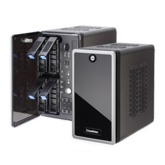
Chapter 2 Overview 2.1 Front View Figure 2-1 No. Name Name HDD x 4 Not Functional Not Functional IR Receiver Not Functional Power Button Not Functional Not Functional Not Functional HDD Activity LED (Red) Reset Button Power LED (Blue) -
Page 13: Rear View
VGA Monitor Output Audio Line Out Port HDMI Port Audio Line In Port USB 2.0 Port x 2 Ethernet Port x 2 PS/2 Port (only for the keyboard) Note: The feature marked with * is for GV-Tower DVR System only. -
Page 14: Chapter 3 Getting Started
DVR/NVR System. Here we use GV-Tower DVR System as the example. Figure 3-1 1. There are two ways to connect the monitor to the GV-Tower DVR/NVR System. • Using the VGA cable supplied by the monitor manufacturer, connect the VGA monitor. -
Page 15: Getting Started
Getting Started Once the above hardware is properly connected, press the Power button on the front panel to start the system. It takes about 1 minute for startup. The system should load automatically and display cameras in the main screen. -
Page 16: Using The Ir Remote Control
3.1.1 Using the IR Remote Control The GV-IR Remote Control provides easy control of the GV-Tower DVR/NVR System. Its receiver is a built-in device. For details, see GV-IR Remote Control User’s Manual (GV-Desktop < Program button < User Manual). Figure 3-2... -
Page 17: Connecting To 2 Monitors
Getting Started 3.1.2 Connecting to 2 Monitors You can connect the 2 monitors to the ports labeled below on the back panel of the GV-Tower DVR/NVR System. Here we use GV-Tower DVR as the example. Figure 3-3 To install other required equipment, follow the steps in 3.1 Basic Installation. -
Page 18: Installing The Hard Drive
3.2 Installing the Hard Drive The GV-Tower DVR/NVR System uses SATA hard drives for video and audio data storage. Before recording, ensure to install your hard drives. Follow the below steps to install the hard drive. 1. Press the release latch. The drawer handle pops up. - Page 19 Figure 3-7 6. Put the drawer back in the drive bay of the GV-Tower DVR/NVR System, and push the latch until it locks. 7. When the Power LED on the drawer shines blue, the hard drive is now ready to use.
-
Page 20: Formatting The Hard Drive
3.3 Formatting the Hard Drive After installing hard drives to your system, you will need to format them before use. 1. On the GV-Desktop, click the Programs button, and select Disk Management. Figure 3-9 2. Type the ID and password in the dialog box. The default ID and password are “0000”. Figure 3-10... - Page 21 Getting Started 3. Right-click in the unallocated space of a new drive, and select New Simple Volume. Figure 3-11 4. The New Simple Volume Wizard appears. Click Next to continue. Figure 3-12...
- Page 22 5. The default partition size is the same as the maximum disk space. Make changes if necessary. Click Next to continue. Figure 3-13 6. Assign a drive path that is not in use by other devices, and click Next to continue. Figure 3-14 Note: The default drive path starts from D:\.
- Page 23 Getting Started 7. Type a name in the Volume label box, ex. HDD1, and click Next to continue. Figure 3-15 8. When the formatting is complete, click Finish to close the wizard. Figure 3-16...
- Page 24 9. When the drive is successfully initialized, partitioned, and formatted, its status description should display “Healthy.” Figure 3-17...
-
Page 25: Adding The Hard Drive To The Recording Path
3. If a hard drive is not inserted, follow these steps: A. Insert a hard drive or plug a USB hard drive to the GV-Tower DVR/NVR System. Figure 3-19... - Page 26 B. Select Add to recording path, and select the storage group from the drop-down list. Note: Storage 1 is the default storage group. 4. Click OK to automatically configure the hard drive to the recording path. 5. In the MediaMan Tools window, if the hard drive is successfully added to store data, its Status field should display “Standby”.
-
Page 27: Setting Up On-Screen Led Panel
Getting Started 3.5 Setting Up On-Screen LED Panel For GV-Tower DVR/NVR System, a LED panel on the screen provides a quick indication of the activity status of hard disk drives. Figure 3-21 LED Color Description - No HDD is assigned to this LED. - Page 28 System: Not functional. Enable disk full beep: When the hard disk drive is full, the system sounds on. Note this function only works when speakers are connected to the GV-Tower DVR/NVR System. 3. By default, only the hard disk drive D will be assigned to LED. If you want to re-assign the hard disk drive or assign other drives to LEDs, freely drag and drop the hard disk drive to the desired LED on the tree.
-
Page 29: Replacing The Hard Drive
Getting Started 3.6 Replacing the Hard Drive You can replace the hard drive without shutting down the GV-Tower DVR/NVR System. 1. Do not turn off the power before you replace the hard drive. 2. Push the release latch. The drawer handle pops up. -
Page 30: Configuring The Ip Address
3.7 Configuring the IP Address GV-Tower DVR/NVR System supports remote monitoring, control and configuration over a network connection. The following default IP addresses will automatically be assigned. • Connection 1: 192.168.0.200 • Connection 2: 192.168.0.201 • Default Subnet Mask: 255.255.252.0 To change the above default IP addresses, follow the steps below. - Page 31 Getting Started 3. Under Network and Internet, click View network status and tasks. Figure 3-24 4. Under Connections, select the Local Area Connection you want to configure. Figure 3-25...
- Page 32 The local area connections listed correspond to the Ethernet ports as shown below: Local Area Connection 1 Default IP: 192.168.0.200 Local Area Connection 2 Default IP: 192.168.0.201 Figure 3-26 5. Select Internet Protocol Version 4 (TCP/IPv4), and select Properties. Figure 3-27...
- Page 33 Getting Started 6. Select Use the following IP address and type the new IP information in the fields. Or select Obtain an IP address automatically to enable dynamic IP address. Figure 3-28 7. Click OK to finish the setting.
-
Page 34: Exiting To Windows
3.8 Exiting to Windows GV-Tower DVR/NVR System is protected by GV-Desktop that is limited to run the selected programs. If you need to exit to Windows desktop, follow these steps. 1. Exit the main screen to display the GV-Desktop screen. -
Page 35: Returning To Gv-Desktop
Getting Started 3.9 Returning to GV-Desktop To return to GV-Desktop, click the Windows Start button, point to All Programs, click GV-DVR/NVR, and click Key Lock Utility. Figure 3-31... -
Page 36: Twin View Display
3.10 Twin View Display You can display live view and play back video in two separated monitors. 1. Follow Steps 1 and 2 in 3.7 Configuring the IP Address to access the Control Panel window. See Figure 3-23. 2. In the Control Panel window, click Adjust Screen Resolution under the Appearance and Personalization section. - Page 37 Getting Started 8. Click the Up button on the toolbar, go to the system folder and locate DMPOS.exe. Figure 3-33 9. Double-click DMPOS.exe. The Set Application Function Position dialog box appears. Figure 3-34 10. In the Screen Setup tab, select TwinView from the Displayer Mode drop-down list. 11.
-
Page 38: Digital Matrix
3.11 Digital Matrix To display multiple channels through two monitors, Digital Matrix is thus introduced to provide a method. The Digital Matrix includes these features: Live view: You can set different live views and screen divisions for each monitor. Automatic channel scan: You can set up to 16 scanned pages with different screen divisions and channels for each monitor. -
Page 39: Setting Live View
Getting Started 3.11.2 Setting Live View You can set different live views and screen divisions for each monitor. 1. On the main screen, click the Configure button, click Accessories, and select Digital Matrix Setting. This dialog box appears. Figure 3-35 2. -
Page 40: Setting Scanned
3.11.3 Setting Scanned Pages You can set up to 16 scanned pages with different screen divisions and channels for each monitor. 1. Use the Display list to select the monitor to be configured. 2. In the upper-left column, expand the Matrix folder tree, and click Page 1. This page appears. -
Page 41: Setting Pop-Up Alert
Getting Started 3.11.4 Setting Pop-up Alert You can be alerted by pop-up live videos when motion is detected or I/O devices are triggered. 1. Use the Display list to select the monitor to be configured. 2. In the upper-left column, click Event Popup. This page appears. Figure 3-37 Motion Trigger: The live video of selected cameras pops up when motion is detected. -
Page 42: Setting Pop-Up Positions
3.11.4.1 Setting Pop-up Positions When you select Random Position of Camera, you can decide the positions for pop-up cameras. Fixed Position of Camera: The cameras pop up in their assigned positions. To assign positions, select Screen Division. Then drag and drop the cameras number to the desired potions on the divisions. -
Page 43: Setting Live View With Pop-Up Alert
Getting Started 3.11.5 Setting Live View with Pop-up Alert You can set a different live view mode with pop-up alert together for each monitor. When alert events occur, the live video of the associated camera will pop up on the assigned monitor to replace its live view mode. -
Page 44: System Restoration
1. On the GV-Desktop, click the Program button and select Recovery. The system will run this command by itself. Figure 3-38 2. Restart the GV-Tower DVR/NVR System. 3. Press F11 button several times to avoid accessing the system. - Page 45 Getting Started 4. When the below screen appears, press the Recovery button. Figure 3-39 5. When the restoring process is completed, the screen will automatically show the GV-Desktop. And the system will restore the default values.
-
Page 46: Changing Video Standard After Recovery
The default video standard after recovery is set to NTSC. If the video standard in your country is PAL, remember to configure the GV-Tower DVR/NVR System for PAL after recovery . 1. Click the Configure button, point to A/V Setting, and then select Video Source. -
Page 47: Updating Gv-Tower Dvr/Nvr System
Getting Started 3.13 Updating GV-Tower DVR/NVR System If you like to update your GV-Tower DVR/NVR System, contact your dealer for more information. Before contacting your dealer, you may check software update news at our website: http://www.geovision.com.tw... -
Page 48: Chapter 4 Nvr Health Analysis
It is recommended to have the health analysis during the first week after you install the GV-Tower DVR/NVR System, and then have the checkup every three months. It will take 5 working days for response. - Page 49 Health Analysis 2. Select Backup MultiCam Settings or Restore Defaults, and select Backup Current System. This dialog box appears. Figure 4-2 3. Press the Next Step button to back up all your system settings. The Save As dialog box appears. 4.
-
Page 50: System Log
4.2 System Log Please provide the sys*.mdb files of system log. The files by default are saved at C:\GV folder\database. If you have modified the default location, you can check the path by the following steps: 1. Click the Configure button on the Main System, select System Configure, and then select System Log Setting. -
Page 51: Information Of Your Computer System
Health Analysis 4.3 Information of Your Computer System To get the information of your computer system, please follow the steps below to install the free software PC WIZARD. By using the software, the following computer information can be easily collected and saved for analysis: Processor: includes Type, Frequency, Data Cache L1, Trace Cache L1, Cache L2, Voltage, Processor Temperature, FPU Coprocessor. - Page 52 4. In the Save As dialog box, select Format HTML and click OK. Figure 4-5 5. Select the Save location, type the file name, and then click Save to save the Processor information as HTML file. 6. Repeat Steps 3-5 to save the Drives information as HTML file.
-
Page 53: Health Analysis Form
Health Analysis 4.4 Health Analysis Form Please send the related data for analysis along with this Health Analysis Form to dvrsystem@geovision.com.tw. Health Analysis of GV-Tower DVR/NVR System Contact Person: Title: Company Name: Telephone: (O) Fax: E-Mail: Model: Bar Code: 4.5 Check List... -
Page 54: Chapter 5 Troubleshooting
1. Restart your GV-Tower DVR/NVR System by pressing the Reset button on the front panel. 2. If your GV-Tower DVR/NVR System is still unresponsive, press the Power button to shut it down. Wait 30 seconds and then restart your GV-Tower DVR/NVR System. - Page 55 Troubleshooting GV-Tower DVR/NVR System hard disk corrupts. If you are experiencing file system corruption problems, such as lost clusters, cross-linked files or invalid files or directories, try these steps: 1. Use the HD Tune utility to scan the hard disk for errors. Follow these steps: A.
- Page 56 2. If the HD Tune utility does not find any defects, use the Windows built-in utility to attempt to fix the errors. Follow these steps: A. On the GV-Desktop, click the Programs button, and select Disk Management. See Figure 3-9. B.
- Page 57 GV-Tower DVR System has video and/or audio lost. If your GV-Tower DVR System fails to show video, audio or both, try these steps: 1. Check the video/audio connection. Make sure one end of the LFH audio & video cable is securely connected to the video/audio device, and the other end to the video/audio port of the GV-Tower DVR System.
-
Page 58: Specifications
Specifications GV-Tower DVR/NVR System Hardware System Intel Core i3 Processor Intel Core i5 Processor (optional) 4 GB Dual Channels 4 (3.5” HDD) No. of HDD 16 GB (DOM) Internal Storage 32 GB (DOM) bundled with i5 Processor 64-bit Windows Embedded Standard 7... - Page 59 Specifications Video and Audio Model GV-Tower DVR System 480 FPS Display NTSC Rate (Max) 400 FPS HW: 480 (D1) NTSC Recording Rate (Max) HW: 400 (D1) HW: 704 x 480 NTSC Video SW: 352 x 240 HW: 704 x 576...
- Page 60 System Monitoring and Recovery Power Restoration Automatic restart after power outage Two independent Watchdogs Monitoring (Hardware Watchdog + Software Watchdog) Recovery Automatic system rebuild from internal hard disk. Language Type Arabic / Bulgarian / Czech / Danish / Dutch / English / Finnish / French / German / Greek / Hebrew / Hungarian / Italian / Japanese / Lithuanian / Norwegian / Polish / Portuguese / Romanian / Russian / Serbian / Simplified Chinese / Slovakian...
-
Page 61: Appendix
Appendix Appendix A. Hard Disk Requirements The total of recording frame rates that you can assign to a single hard disk is listed as below: Frame rate limit in a single hard disk when connecting to analog cameras Analog Cameras / SW Compression MPEG4 Video Resolution NTSC... -
Page 62: B Total Frame Rate Supported
B. Total Frame Rate Supported Below are the total frame rates GV-Tower DVR/NVR System can support with CPU usage of approximately 70% to ensure performance and stability. You could connect up to 32 cameras to the system. See the below charts to calculate frame rate for connected IP cameras. -
Page 63: C Supported Ip Devices
Appendix C. Supported IP Devices This list provides the supported IP device brands. For detailed information on the supported IP devices, refer to Supported IP Camera List on GeoVision’s Website: http://www.geovision.com.tw/english/4_21.asp GeoVision ACTi Arecont Vision AXIS Bosch Canon D-Link Etrovision... -
Page 64: Warranty Policy
Warranties do not apply to any non-GeoVision products including counterfeited products. GeoVision is not liable for any damage to or loss of any profit, programs, data, or other information stored on any media, or any non-GeoVision products or part not covered by these warranties. - Page 65 Warranty Policy of any stickers or labels on the hardware, improper hardware/software installations, or other acts that are not the faults of GeoVision, including damage caused by shipping; b) Products have been damaged from exposure under circumstances which is over...
-
Page 66: Limitation Of Liability
Regardless whether any remedy set forth herein fails of its essential purpose or otherwise, in no event will GeoVision or its suppliers be liable for any lost revenue, profit or lost or damaged data, business interruption, loss of capital, or for special, indirect, consequential, incidental, or... -
Page 67: Warranty Requirements
To validate your purchase, you shall complete the online Product Registration within 30 days from the date of purchase at http://www.geovision.com.tw/english/4_6.asp. Or click GeoVision Online Registration in My Favorite for a direct link. If you fail to complete the Product Registration, the warranty period will start from the date of shipment. - Page 68 2. Securely pack the product in its original carton using the original packing material, or in equivalent packaging. 3. The product shall be returned to GeoVision, Taiwan at your expense for shipping and insurance costs. BEFORE YOU DELIVER YOUR GV-TOWER DVR/NVR SYSTEM FOR WARRANTY SERVICE, IT IS YOUR RESPONSIBILITY TO BACK UP YOUR DATA.
-
Page 69: Warranty Form
Warranty Form Warranty Form Thank you for purchasing the GV-Tower DVR/NVR System. To help us validate your purchase and better serve you in the future, please go to http://www.geovision.com.tw/english/4_6.asp or click GeoVision Online Registration in My Favorite for a direct link to register online within 30 days from the date of purchase. - Page 70 Bar Code: Shipment Date: GeoVision, Inc. 9F, No. 246, Sec. 1, Neihu Rd., Neihu District, Taipei, Taiwan Tel: +886-2-8797-8377 Fax: +886-2-8797-8335 Email: sales@geovision.com.tw dvrsystem@geovision.com.tw http://www.geovision.com.tw...
Need help?
Do you have a question about the GV-Tower and is the answer not in the manual?
Questions and answers