GeoVision GV-Compact DVR V2 User Manual
Mobile video recorder
Hide thumbs
Also See for GV-Compact DVR V2:
- User manual (223 pages) ,
- Quick start manual (31 pages) ,
- How-to (4 pages)
Table of Contents
Advertisement
Quick Links
Download this manual
See also:
User Manual
Advertisement
Table of Contents

Related Manuals for GeoVision GV-Compact DVR V2


Summary of Contents for GeoVision GV-Compact DVR V2
- Page 1 GV-Compact DVR V2 User's Manual Before attempting to connect or operate this product, please read these instructions carefully and save this manual for future use.
- Page 2 9F, No. 246, Sec. 1, Neihu Rd., Neihu District, Taipei, Taiwan Tel: +886-2-8797-8377 Fax: +886-2-8797-8335 http://www.geovision.com.tw Trademarks used in this manual: GeoVision, the GeoVision logo and GV series products are trademarks of GeoVision, Inc. Windows and Windows XP are registered trademarks of Microsoft Corporation. April 2009...
-
Page 3: Table Of Contents
Contents Chapter 1 Introduction ............1 Features.........................1 Models ........................2 Packing List......................3 Options ........................5 Chapter 2 Physical Description..........6 Front Panel ......................6 Rear Panel ......................8 Rear Panel ......................8 Remote Control.....................9 Chapter 3 Getting Started ...........11 Basic Connection ....................12 3.1.1 Connecting Vehicle Power Supply............13 3.1.2 Connecting Optional Video Output Devices..........14 Installing Hard Drive...................15... - Page 4 4.1.8 PTZ Control....................29 Digital IO Settings....................30 4.2.1 Digital Input Settings .................30 4.2.2 Digital Output Settings ................31 4.2.3 GPS Settings ....................32 Events and Alerts ....................33 4.3.1 E-mail......................33 4.3.2 FTP ......................34 4.3.3 Center V2....................35 4.3.4 VSM ......................36 4.3.5 Remote Playback..................37 4.3.6 3GPP ......................38 Monitoring Settings ....................39 Recording Schedule ...................40 4.5.1...
- Page 5 5.1.1 Using OSD Menu ..................60 5.1.2 Connecting with a PC ................61 Accessing Your Surveillance Images ...............63 Functions Featured on the Main Page..............64 5.3.1 The Live View Window................65 5.3.2 The Control Panel of the Live View Window..........66 5.3.3 Snapshot of a Live Video ................67 5.3.4 Video Recording ..................67 5.3.5...
- Page 6 6.7.2 Wireless-Client Mode................105 6.7.3 Advanced TCP/IP ...................107 6.7.4 UMTS......................109 6.7.5 IP Filter....................110 Management......................111 6.8.1 Date & Time Setting................111 6.8.2 GPS Maps Settings.................113 6.8.3 Storage Settings ..................114 6.8.4 iSCSI Storage Settings ................116 6.8.5 User Account ..................117 6.8.6 Log Information ..................117 6.8.7 Tools .......................118 Chapter 7 Remote Recording and Playback ....119 Remote Recording....................119...
- Page 7 Chapter 12 The I/O Terminal Block ........145 12.1 Pin Assignment....................145 12.2 Relay Output .....................146 12.3 Camera Power Supply..................147 Specifications ...............148 Appendix ................150 Supported Wireless LAN USB Adaptor ..........150 Supported Mobile Broadband Device ..........150...
-
Page 8: Chapter 1 Introduction
The special design of the GV-Compact DVR V2 enables you to link up with TV, VGA and spot monitors simultaneously for direct display. The GV-Compact DVR V2 offers many features that you can expect to have. -
Page 9: Models
Standard Model (GV-LX4C2) • Anti-Vibration Model (GV-LX4C2V) The GV-Compact DVR V2 V2, equipped with vibration absorbers, can withstand severe levels of shock and vibration in mobile environments. Caution: The standard and anti-vibration models have different internal designs. It is forbidden to connect the standard model to the vehicle power supply. -
Page 10: Packing List
• AC Power Cord x 1 • Lock Key x 2 • GV-Compact DVR V2 Remote Control • GV-Compact DVR V2 Software DVD x 1 • GV-Compact DVR V2 User’s Manual x 1 • Anti-Vibration Model (GV-LX4C2V) • • D-Type Video Cable x 1... - Page 11 Camera Power Adapter x 1 Cigarette Lighter Power Adapter x 1 • Lock Key x 2 • GV-Compact DVR V2 Remote Control x 1 • GV-Compact DVR V2 Software DVD x 1 • GV-Compact DVR V2 User’s Manual x 1 The optional accessories contain the following items: •...
-
Page 12: Options
Introduction 1.4 Options Optional devices can expand your GV-Compact DVR V2’s capabilities and versatility. Contact your dealer for more information. The external IR receiver, with a 5-meter cable (16.4 feet), External IR Receiver allows long-distance remote control of the GV-Compact DVR... -
Page 13: Chapter 2 Physical Description
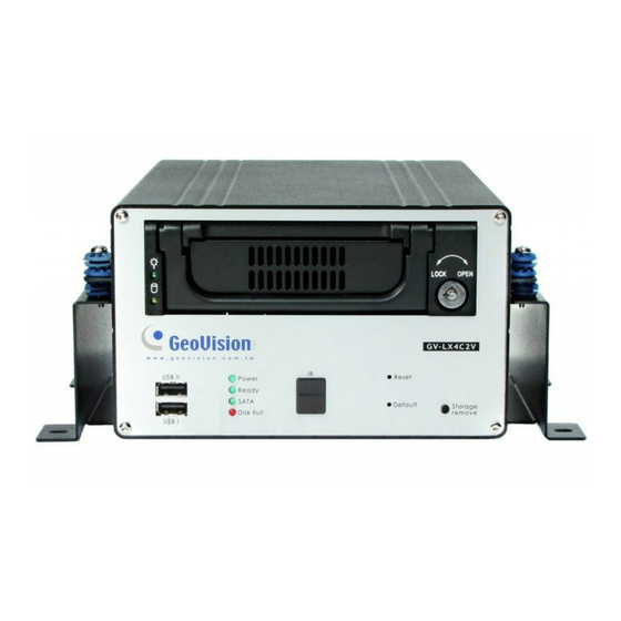
Chapter 2 Physical Description This section identifies the various components of the GV-Compact DVR V2, and provides the overview of the remote control. 2.1 Front Panel Figure 2-1 Description No. Name The two USB ports can connect the USB storage device, USB Port Wireless LAN adaptor and/or mobile Internet device. -
Page 14: Physical Description
Physical Description LED is on. You have then successfully returned to the default settings. Stops recording and removes the HDD from the system. If Storage Removal Button the unit is installed in a vehicle, ensure to press the button before turning off the ignition to protect the recorded data. Installs the SATA hard drive for recording. -
Page 15: Rear Panel
2.2 Rear Panel Figure 2-2 No. Name Description Connects to power supply. DC Power Input (12V) Connects to the optional External IR Receiver. External IR Receiver Port When using the Loop function, please switch to Off. The 75 Ω default setting is On. •... -
Page 16: Remote Control
Physical Description 2.3 Remote Control The GV-Compact DVR V2 Remote Control is provided to configure and operate the GV-Compact DVR V2. Figure 2-3 Button Description Stops recording. Starts recording. OSD menu: Moves the focus upward to the desired item. Playback: Decreases the speed of playback. - Page 17 Quits the menu selection or exits the menu. A / B / C Switches the device type for the control of GV-Compact DVR V2 Remote Device Type Control. To set the device type of the GV-Compact DVR V2, see IR TYPE, 4.8.4 Display Settings.
-
Page 18: Chapter 3 Getting Started
Getting Started Chapter 3 Getting Started Getting started with the GV-Compact DVR V2 consists of the following steps: 3.1 Connection Install the video display devices to the unit. 3.2 Installing Hard Drive Install a hard drive for video recording. 3.3 Turning on and off the Power Turn on and off the unit. -
Page 19: Basic Connection
3.1 Basic Connection The following instructions describe the basic connection to the GV-Compact DVR V2. Figure 3-1 1. Connect power. Using the supplied power adaptor, connect to the power. 2. Connect video input. Using the blue connectors of the supplied D-Type Video Cable, connect to cameras. -
Page 20: Connecting Vehicle Power Supply
The connections are for the anti-vibration model. Using the supplied Car Cigarette Power Adaptor, connect one end to the DC power input on the GV-Compact DVR V2 and the other end to a car‘s cigarette lighter socket. The car battery will supply power to the unit. -
Page 21: Connecting Optional Video Output Devices
3.1.2 Connecting Optional Video Output Devices The GV-Compact DVR V2 offers the looping video outputs for 4 monitors. The GV-Compact DVR V2 also offers the spot monitor output to display video sequentially from each video input. For the settings of the spot monitor, see 4.8.5 Spot Monitor Settings. -
Page 22: Installing Hard Drive
Getting Started 3.2 Installing Hard Drive The GV-Compact DVR V2 comes equipped with a 3.5” SATA hard drive bay for video recording. Follow these steps to install the hard drive. 1. Make sure the unit is powered off. 2. Open the door of drive bay, push the hard drive inside, and close the door. -
Page 23: Turning On / Off The Power
4 channels will be displayed. If the GV-Compact DVR V2 is connected to a vehicle power supply, the unit will automatically start once you turn on the vehicle ignition. Power is supplied to the unit as long as the vehicle ignition is on. -
Page 24: Formatting Hard Drive
Getting Started 3.4 Formatting Hard Drive The GV-Compact DVR V2 is a Linux-based system. You must follow the steps below to format the hard drive before recording. 1. Press the Menu button on the Remote Control to enter the main menu. -
Page 25: Main Screen Overview
Figure 3-8 1. Date and time: Indicates the current date and time when viewing live video. 2. A / B / C: Indicates the type of device defined for GV-Compact DVR V2 Remote Control. 3. Monitoring icon : Appears when the monitoring is activated. -
Page 26: Basic Operation
To start recording, press the REC button on the Remote Control to record video onto the hard drive with the corresponding programmed recording settings. The RED recording icon will appear on the corresponding camera screen. The SATA LED and HDD Activity LED lights will be blinking, indicating the GV-Compact DVR V2 is in recording mode. -
Page 27: Search/Playback Operation
• To stop recording, press the Stop button on the Remote Control at any time. Steps Set the recording mode Press the Menu button and select MONITORING SETTINGS. Activate the audio recording 1. Press the Menu button, select CHANNEL SETTINGS, press one Channel button (Ch1 - CH4), and select VIDEO/AUDIO SETTINGS. -
Page 28: Chapter 4 Osd Menu Configurations
OSD Menu Configurations Chapter 4 OSD Menu Configurations The GV-Compact DVR V2 is configured through a series of menus on screen by using the Remote Control. This section describes the functions and options in the on-screen display (OSD) menus. To enter the main menu, press the Menu button on the Remote Control. Eight submenus will appear as shown below. - Page 29 List of Main Menu Options Find the topic of interest by referring to the section number prefixed to each option. 4.1.1 CHANNEL NAME 4.1.2 VIDEO/AUDIO SETTINGS 4.1.3 MOTION DETECTION 4.1.4 MOTION TRIGGER OUTPUT SETTINGS 4.1 CHANNEL SETTINGS 4.1.5 ALARM SETTINGS 4.1.6 CAMERA SETTINGS 4.1.7 PTZ SETTINGS 4.1.8 PTZ CONTROL...
-
Page 30: Channel Settings
OSD Menu Configurations 4.1 Channel Settings In Channel Settings, you can adjust the device settings for each channel. To set up a channel, press the Menu button on the Remote Control, select CHANNEL SETTINGS, press one Channel button, and select one of the setting options. These setting options are described in the following. -
Page 31: Video/Audio Settings
4.1.2 Video/Audio Settings You can adjust the audio and video settings for the selected channel. Select APPLY TO ALL to apply the same settings to all four channels. Figure 4-3 VIDEO RESOLUTION: Select the video resolution from 720 x 480, 720 x 240, 360 x 240, 360 x 240 3GPP v7 for NTSC format;... -
Page 32: Motion Detection
OSD Menu Configurations 4.1.3 Motion Detection Motion detection is used to generate an alarm whenever movement occurs in the video image. You can configure up to 8 areas of different sensitive values for motion detection. 1. Select MOTION DETECTION. This screen appears. The default sensitivity value is 2 for the whole area. - Page 33 5. Press the directional buttons to place the detection area, and press the button. 6. Press the directional buttons to modify the size of the detection area, and press the button. Figure 4-6 7. Select SENSITIVITY value from Low (1), Medium (2) and High (3), and press the button.
-
Page 34: Motion Trigger Output Settings
OSD Menu Configurations 4.1.4 Motion Trigger Output Settings The alarm output can be triggered simultaneously when motion is detected. To activate the output settings, you must also start monitoring manually or by schedule. See 4.4 Monitoring Settings. Figure 4-8 4.1.5 Alarm Settings You can capture images before and/or after a motion and an I/O event happens. -
Page 35: Camera Settings
Through the RS-485 interface on the I/O terminal block, you can connect up to 4 PTZ cameras. To set up the baud rate, speed and address, consult your PTZ documentation. Figure 4-11 Note: Currently the GV-Compact DVR V2 does not support the PTZ camera with RS-232 interface. -
Page 36: Ptz Control
OSD Menu Configurations 4.1.8 PTZ Control After setting up the PTZ camera, you can press the Channel button on the remote Control to display the PTZ channel. Use the directional buttons to control the PTZ movement. Press the Menu button to access advanced functions. The availability of certain PTZ functions depends on different models. -
Page 37: Digital Io Settings
GPS. 4.2.1 Digital Input Settings The GV-Compact DVR V2 can connect up to 4 input devices. To select one input device for setup, press the desired Channel button on the Remote Control. -
Page 38: Digital Output Settings
OSD Menu Configurations 4.2.2 Digital Output Settings The GV-Compact DVR V2 can connect up to 4 output devices. To select one output device for setup, press the desired Channel button on the Remote Control. Figure 4-14 STATE: Enable the selected output. -
Page 39: Gps Settings
UPDATE PERIOD: Set the update frequency in seconds for GPS data. After the GPS function is activated, you can view the location of the GV-Compact DVR V2 on Google Maps. See 8.3 GPS Tracking. If the monitoring is also activated, the GPS tracks will be recorded along with videos. -
Page 40: Events And Alerts
The functions of FTP alerts and the monitoring through GV-GIS are only available in web-based configurations. See Chapter 6 Remote Configurations. 4.3.1 E-mail After a trigger event, the GV-Compact DVR V2 can send the e-mail to a remote user containing a captured still image. Figure 4-16 STATE: Enable the e-mail function. -
Page 41: Ftp
See 6.3.1 E-mail. 4.3.2 FTP You can enable the GV-Compact DVR V2 to act as a FTP server, allowing users to download the AVI files. The default download port is 21. For how to download AVI files saved on the GV-Compact DVR V2, see [Act as a FTP Server], 6.3.2 FTP. -
Page 42: Center V2
OSD Menu Configurations 4.3.3 Center V2 After a motion or an I/O triggered event, the central monitoring station Center V2 can get notified by live videos and text alerts. For the lmonitoring through Center V2, you must already have a subscriber account on Center V2. Figure 4-18 ACTIVATE LINK: Enable the monitoring through Center V2 for alert events. -
Page 43: Vsm
4.3.4 VSM After a motion or an I/O triggered event, the central monitoring station VSM can get notified by text alerts. For the monitoring through VSM, you must already have a subscriber account on VSM. Figure 4-19 ACTIVATE LINK: Enable the monitoring through VSM for alert events. HOSTNAME/IP: Enter the host name or IP address of VSM. -
Page 44: Remote Playback
OSD Menu Configurations 4.3.5 Remote Playback You can remotely access the recorded files saved at the GV-Compact DVR V2 and play back video with the ViewLog player. Select YES to activate the remote playback server built in the unit. Keep the default port 5552 or modify it if necessary. -
Page 45: 3Gpp
3GPP server, you can receive live video streaming from the GV-Compact DVR V2 by entering the IP address (domain name) and password of the GV-Compact DVR V2 on the 3G-enable mobile phone. See Chapter 9 Mobile Phone Surveillance. -
Page 46: Monitoring Settings
OSD Menu Configurations 4.4 Monitoring Settings You can start recording manually, by schedule or by input trigger. Figure 4-22 MONITORING MODE: Select MANUAL to manually start recording or I/O monitoring. If you choose this option, configure the following item CHANNEL (CH 1 – CH 4) or INPUT. Select SCHEDULE to start recording and I/O monitoring by the schedule you set up. -
Page 47: Recording Schedule
To start monitoring or recording: • Select START. The unit will start monitoring based on your above settings: record immediately, only record on the scheduled time, or record by an input trigger.. –OR- • Select SAVE to save the monitoring settings. Then press the REC button on the Remote Control at any time to start your monitoring settings. -
Page 48: Channel Schedule
OSD Menu Configurations 4.5.2 Channel Schedule You can set up different monitoring schedules for each camera. Press the Channel button on the Remote Control to select one channel for setup. Figure 4-24 Span 1- Span 3: Sets different recording modes for each time frame during the day. Each day can be divided into 3 time frames, represented by Span 1 to Span 3. -
Page 49: I/O Monitoring Schedule
4.5.3 I/O Monitoring Schedule You can set up the schedule for I/O monitoring to start. Figure 4-25 Span 1- Span 3: Set different time frames during the day to enable I/O monitoring. Each day can be divided into 3 time frames, represented by Span 1 to Span 3. Weekend: If you don’t want to apply the span settings to the weekend and need the I/O monitoring for the whole day, enable this option and define whether your weekend includes Saturday and Sunday (SAT-SUN) or Only Sunday (SUN). -
Page 50: Search/Playback
OSD Menu Configurations 4.6 Search/Playback You can retrieve the recorded video by date, time and event. To access the SEARCH/PLAYBACK menu, press the Menu button or the Search button on the Remote Control. 4.6.1 Time Map List The Time Map List provides an overview of the recorded videos in the form of a calendar. 1. -
Page 51: List All
3. In the MIN section, minutes for which there are recorded videos are green. Each column represents 2 minutes. Select the desired minute and press the button to start playback. 4.6.2 List All The list displays a complete list of recorded videos. To move the list screen up and down one page, press the right and left directional buttons on the Remote Control. -
Page 52: Advanced Search
OSD Menu Configurations 4.6.7 Advanced Search You can limit your search by defining search criteria. Figure 4-28 SOURCE: Search the recorded video from the selected channel or all channels. EVENT: Select the type of recorded videos with the options of MOTION + IO, MOTION, ALL IO, IO 1, IO 2, IO 3 and IO 4. -
Page 53: Network
4.7 Network The GV-Compact DVR V2 allows you to use a Web browser to remotely view and manage the system. For remote access, configure the related network settings in this section. To assign an IP address to the Compact DVR, see Chapter 5 Remote Viewing Using A Web Browser. -
Page 54: Connection Settings
Before enabling WIRELESS, configure WIRELESS SETTINGS which is explained in the following section. GAIN IP: FIXED: Assign a static IP or fixed IP to the GV-Compact DVR V2. Enter the GV-Compact DVR V2’s static IP address, subnet mask, gateway, primary DNS and secondary DNS. -
Page 55: Wireless Settings
4.7.3 Wireless Settings To use the wireless function, a wireless LAN USB Adaptor is required. For supported wireless LAN adaptors, see Appendix A. Figure 4-31 NETWORK TYPE: Select AD HOC or INFRASTRUCTURE for the network mode. AD HOC: A Peer-to-Peer mode. This mode connects to other computer with the WLAN card, and does not need the Access Point to connect to each other. -
Page 56: Advanced Tcp/Ip
Figure 4-32 HOST NAME: Enter a descriptive name for the GV-Compact DVR V2. HTTP PORT: The HTTP port enables connecting the GV-Compact DVR V2 to the web. For security integration, the Administrator can hide the server from the general HTTP port by changing the default HTTP port of 80 to a different port number within the range of 1024 thru 65535. -
Page 57: Umts Settings
IP Address: The IP address of the GV-Compact DVR V2 will be displayed after enabling the UMTS service. The next time when you want to log in the GV-Compact DVR V2, you need to enter the IP address into your browser. If you use the UMTS connection with dynamic IP addresses, it is highly suggested to enable the DDNS function that links a domain name to the unit’s changing IP address. -
Page 58: Ddns Settings
DDNS (Dynamic Domain Name System) provides a convenient way of accessing the GV-Compact DVR V2 when using a dynamic IP. DDNS assigns a domain name to the unit, so that the Administrator does not need to go through the trouble of checking if the IP address assigned by DHCP server or ISP (in xDSL connection) has changed. -
Page 59: Web User Account Info
4.7.7 Web User Account Info You can change the login name and password of Administrator, Guest and FTP Server User. • The default Administrator login name and password are admin. • The default Guest login name and password are guest. •... -
Page 60: Advanced
If you select NETWORK, then the option of SERVER appears. Use the on-screen keypad to enter the IP address of the time server. DAY LIGHT SAVING: Automatically adjust the GV-Compact DVR V2 for daylight saving time. Enter the Start and End time of daylight saving. -
Page 61: Firmware Settings
GeoVision will periodically release the updated firmware on the website. The new firmware can be simply loaded into the GV-Compact DVR V2 by using the USB storage device. For the details on upgrading the unit over the Internet, see Chapter 8 Advanced Applications. - Page 62 OSD Menu Configurations ISCSI STORAGE SETTINGS: Connect the GV-Compact DVR V2 to the iSCSI storage system. Enter initiator node name and the IP address of iSCSI data port 1 or data port 2. RECYCLING: If the option is enabled, the system will either write the data to another device or overwrite the oldest recorded files when the disk space is lower than the specified space limit.
-
Page 63: Display Settings
4.8.4 Display Settings You can show or hide the time, date, disk space, camera information and specific cameras appearing on the screen. Figure 4-39 INFO DISPLAY SETTINGS: Show or hide the information of date and time, hard disk space, channel number and camera name on the image. The INSTRUCTIONS option allows you to show or hide the legend at the bottom of the screen. -
Page 64: Spot Monitor Settings
OSD Menu Configurations 4.8.5 Spot Monitor Settings You can configure the settings when a spot monitor is connected to the GV-Compact DVR V2. Figure 4-40 NORMAL DWELL TIME: Select the amount of time that each video remains on the spot monitor before the GV-Compact DVR V2 switches to the next video in a rotation. -
Page 65: Alert Settings
4.8.6 Alert Settings The system buzzer can be activated automatically under these conditions: video lost, input device triggered, motion detected, disk full and disk write error. The duration of buzzing sounds is definable. When the buzzer starts beeping, pressing any button on the Remote Control can stop it. -
Page 66: System Log
OSD Menu Configurations 4.8.8 System Log You can view and save the events logged on GV-Compact DVR V2. To back up the log, connect a USB mass storage device to the unit. And then press the REC button on the Remote Control to start the backup. -
Page 67: Chapter 5 Remote Viewing Using A Web Browser
Chapter 5 Remote Viewing Using A Web Browser Not only can the GV-Compact DVR V2 operate as a standalone, but also a networked device. Using the Internet Explorer, you can remotely access and manage the GV-Compact DVR V2. 5.1 Assigning an IP Address Designed for use on an Ethernet network, the GV-Compact DVR V2 must be assigned an IP address to make it accessible. -
Page 68: Connecting With A Pc
Remote Viewing Using a Web Browser 5.1.2 Connecting with a PC Use a computer on the same LAN with the GV-Compact DVR V2 to assign the IP address. The GV-Compact DVR V2 has a default address of 192.168.0.10. The computer used to set the IP address must be under the same IP and subnet sequence assigned to the unit. - Page 69 Important: • If Dynamic IP Address and PPPoE is enabled, your must check the current IP address from the OSD screen of Network Status (Figure 4-28) every time before logging in the unit. Otherwise, you may enable the DDNS function that links a domain name to the unit’s changing IP address first.
-
Page 70: Accessing Your Surveillance Images
Once installed, the GV-Compact DVR V2 is accessible on a network. Follow these steps to access your surveillance images: 1. Start the Internet Explorer browser. 2. Enter the IP address or the domain name of the GV-Compact DVR V2 in the Location/Address field of your browser. Figure 5-3 3. -
Page 71: Functions Featured On The Main Page
5.3 Functions Featured on the Main Page Two types of users are allowed to log in the GV-Compact DVR V2: Administrator and Guest. The Administrator has unrestricted access to all system configurations, while the Guest has the access to live view and network status only. This section introduces the live view functions and the network status on the main page, which can be accessed by both Administrator and Guest. -
Page 72: The Live View Window
Remote Viewing Using a Web Browser 5.3.1 The Live View Window In the left menu, click Live View, and then select Camera 1, Camera 2, Camera 3, Camera 4 or 4 Cameras to see the live video. 2 3 4 5 6 7 Figure 5-5 No. -
Page 73: The Control Panel Of The Live View Window
Figure 5-6 [Information] Displays the version of the GV-Compact DVR V2, local time of the local computer, host time of the GV-Compact DVR V2, and the number of users logging in to the GV-Compact DVR V2. [Video] Displays the current video codec, resolution and data rate. -
Page 74: Snapshot Of A Live Video
Remote Viewing Using a Web Browser 5.3.3 Snapshot of a Live Video To take a snapshot of live video, follow these steps: 1. Click the Snapshot button (No. 5, Figure 5-5). The Save As dialog box appears. 2. Specify Save in, type the File name, and select JPEG or BMP as Save as Type. You may also choose whether to display the name and date stamps on the image. - Page 75 Picture-in-Picture View With the Picture in Picture (PIP) view, you can crop the video to get a close-up view or zoom in on the video. Navigation box Inset window Figure 5-7 1. Select PIP. An inset window appears. 2. Click the insert window. A navigation box appears. 3.
-
Page 76: Remote Viewing Using A Web Browser
Remote Viewing Using a Web Browser Picture-and-Picture View With the Picture and Picture (PAP) view, you can create a split video effect with multiple close-up views on the image. A total of 7 close-up views can be defined. Figure 5-8 Select PAP. -
Page 77: Alarm Notification
5.3.6 Alarm Notification After input triggers and motion detection, you can be alerted by a pop-up live video and view up to four captured images. Pop-up live video Captured images Figure 5-9 To configure this function, click the Show System Menu button (No. 11, Figure 5-5), and select Alarm Notify. -
Page 78: Video And Audio Configuration
Remote Viewing Using a Web Browser 5.3.7 Video and Audio Configuration You can enable the microphone and speaker for two-way audio communication and adjust the audio volume. To change audio configuration, click the Show System Menu button (No. 11, Figure 5-5), and select Video and Audio Configuration. Figure 5-11 5.3.8 Remote Configuration You can view the connection status of the central monitoring stations and upgrade firmware... -
Page 79: Image Enhancement
5.3.10 Image Enhancement To enhance the image quality of live video, click the Show System Menu button (No. 11, Figure 5-5), and select Image Enhance. This dialog box appears. Figure 5-12 De-Interlace: Coverts the interlaced video into non-interlaced video. De-Block: Removes the block-like artifacts from low-quality and highly compressed video. -
Page 80: Visual Ptz
Remote Viewing Using a Web Browser 5.3.12 Visual PTZ In additional to the PTZ control panel, you can display a visual PTZ control panel on the image. This feature is only available when the PTZ is set ahead by the Administrator. For details, see 6.2.1 PTZ Settings. -
Page 81: I/O Control
5.3.13 I/O Control The I/O Control window provides real-time graphic displays of camera and I/O status, and alarm events. Additionally, you can force output to be triggered. Figure 5-15 To display the I/O control window, click the I/O Control button (No. 8, Figure 5-5). The Alarm List is displayed in three levels. -
Page 82: Visual Automation
Remote Viewing Using a Web Browser 5.3.14 Visual Automation The Visual Automation allows you to change the current state of the electronic device by simply clicking on its image, e.g. turning the light ON. This feature is only available when the Visual Automation is set ahead by the Administrator. -
Page 83: Network Status
5.3.15 Network Status To view the network status, in the left menu, click Network and select Status. Figure 5-17... -
Page 84: Chapter 6 Remote Configurations
Remote Configurations Chapter 6 Remote Configurations The Administrator can remotely configure the GV-Compact DVR V2 via the Internet. Eight categories of configurations are involved in the system configuration: Video and Motion, Digital I/O and PTZ, Events and Alerts, Monitoring, Recording Schedule, Remote ViewLog, Network, and Management. -
Page 85: Video & Motion
6.1 Video & Motion This section includes the video image settings and how the images can be managed by using Motion Detection and Visual Automation. 6.1.1 Video Settings Figure 6-2 [Name] Rename the camera. To display the camera name on the image, see 5.3.9 Camera Name Display. - Page 86 Remote Configurations [Video Signal Type] Auto detect signal type on booting: Automatically detects the type of video input is NTSC or PAL. There are 3 options for selecting image resolutions. NTSC 720 x 480 720 x 576 720 x 480 De-interlaced (Default) 720 x 576 De-interlaced (Default) 360 x 240 360 x 288...
-
Page 87: Motion Detection
6.1.2 Motion Detection Motion detection is used to generate an alarm whenever movement occurs in the video image. You can configure up to 8 areas with different sensitivity values for motion detection. Figure 6-3 1. The default sensitivity value is 2 for the whole area. To define a different sensitivity value, click Reset. -
Page 88: Visual Automation
Remote Configurations 6.1.3 Visual Automation This intuitive feature helps you automate any electronic device by triggering the connected output device. When you click on the image of the electronic device, you can simply change its current state, e.g. light ON. Figure 6-4 1. -
Page 89: Digital I/O & Ptz
6.2 Digital I/O & PTZ The I/O terminal block, on the rear panel of the GV-Compact DVR V2, provides the interface for the following applications: 1. Digital Input / Relay Output 2. RS-485 interface for PTZ control 3. RS-232 interface for GPS tracking 6.2.1 PTZ Settings... -
Page 90: Input/Output Settings
Remote Configurations 6.2.2 Input/Output Settings The GV-Compact DVR V2 can connect up to 4 input devices, such as sensors. Normal State: Set up the input state to trigger actions by selecting Open Circuit (N/O) or Grounded Circuit (N/C). Latch Mode: Enable the mode to have a momentary output alarm. - Page 91 The GV-Compact DVR V2 can connect up to 4 output devices, such as alarms. Select Enable to start the output device. Choose the output signal that mostly suits the device you are using: N/O (Open Circuit), N/C (Grounded Circuit), N/O Toggle, N/C Toggle, N/O Pulse and N/C Pulse.
-
Page 92: Gps
Set GPS Update Period: Set the update frequency in seconds for GPS data. After the GPS function is activated, you can view the location of the GV-Compact DVR V2 on Google Maps. See 8.3 GPS Tracking. If the monitoring is also activated, the GPS tracks will be recorded along with videos. -
Page 93: Buzzer
6.2.4 Buzzer The system buzzer can be activated automatically under these conditions: video lost, input device triggered, motion detected, disk full and disk write error. The duration of buzzing sounds is definable. When the buzzer starts beeping, pressing any button on the Remote Control can stop it. -
Page 94: Spot Monitor
Remote Configurations 6.2.5 Spot Monitor If the spot monitor is connected to the GV-Compact DVR V2, configure the settings of the spot monitor. Figure 6-11 Dwell time x seconds: Select the amount of time that each video remains on the spot monitor before the GV-Compact DVR V2 switches to the next video in a rotation. -
Page 95: Events & Alerts
6.3 Events & Alerts For the events of motion detection or I/O trigger, the Administrator can set up these trigger actions: 1. Send a captured still image by e-mail or FTP. 2. Notify Center Monitoring Station, Center V2, VSM or GV-GIS, by video or text alerts. To have above trigger actions, you must also set the following features: •... -
Page 96: E-Mail
Remote Configurations 6.3.1 E-mail After a trigger event, the GV-Compact DVR V2 can send the e-mail to a remote user containing a captured still image. Figure 6-12 [Enable] Select to enable the e-mail function. Sever URL/IP Address: Type the URL or IP address of the SMTP server. -
Page 97: Ftp
6.3.2 FTP You can also send the captured still image to a remote FTP server for alerts. Figure 6-13 [Upload to a FTP Server] Enable: Select to enable the FTP function. Server URL/IP Address: Type the URL or IP address of the FTP Server. Port Number: Type the port number of the FTP Server. - Page 98 Remote Configurations [Act as FTP Server] You can enable the GV-Compact DVR V2 to act as a FTP server, allowing users to download the AVI files. The default download port is 21. To access the internal FTP server through a web browser, enter the IP address or the domain name of the GV-Compact DVR V2 in your browser like this: fpt://192.168.0.10...
-
Page 99: Center V2
6.3.3 Center V2 After a motion or an I/O triggered event, the central monitoring station Center V2 can get notified by live videos and text alerts. For the live monitoring through Center V2, you must already have a subscriber account on Center V2. Figure 6-14 To enable the Center V2 connection: 1. - Page 100 Remote Configurations These options you can also find on this Center V2 setting page: Cease motion detection messages from: Stops notifying Center V2 of motion detection from selected camera(s). Cease input trigger messages from: Stops notifying Center V2 of input trigger from selected input(s).
-
Page 101: Vsm
6.3.4 VSM After a motion or an I/O triggered event, the central monitoring station VSM can get notified by text alerts. For the live monitoring through VSM, you must already have a subscriber account on VSM. Figure 6-15 To enable the VSM connection: 1. -
Page 102: Gv-Gis
Input/Output Settings, and 11.2 VSM. 6.3.5 GV-GIS Through the Internet connection, the GV-Compact DVR V2 with the GPS function enabled can send GPS data and live video to the GV-GIS (Geographic Information System) for the services of vehicle tracking, location verification and live monitoring. - Page 103 Figure 4-16 To enable the GV-GIS connection: 1. Activate Link: Enable the monitoring through GV-GIS. 2. Host Name or IP Address: Type the host name or IP address of GV-GIS. 3. Port Number: Match the communication port on GV-GIS. Or keep the default value 3356. 4.
-
Page 104: Viewlog Server
6.3.6 ViewLog Server The ViewLog Server is designed for remote playback function. This server allows you to remotely access the recorded files saved at the GV-Compact DVR V2 and play back video with the player ViewLog. Select Enable to activate the server built in the unit. Keep the default port 5552 or modify it if necessary. -
Page 105: 3Gpp
The 3GPP Server enables video and audio streaming to your 3G-enabled mobile phone. After enabling the server, you can receive live streaming from the GV-Compact DVR V2 by entering the IP address (domain name) and password of the GV-Compact DVR V2 on the 3G-enable mobile phone. -
Page 106: Monitoring
Remote Configurations 6.4 Monitoring You can start recording manually, by schedule or by input trigger. Figure 6-19 [Manual] Manually activates recording and I/O monitoring. Select one of the following options and then click the Start button. Select all: Manually starts recording and I/O monitoring as well. Camera 1 - Camera 4: Manually starts recording. -
Page 107: Recording Schedule
6.5 Recording Schedule The schedule is provided to activate recording and I/O monitoring on a specific time each day. 6.5.1 Recording Schedule Settings You can set up different monitoring schedules for each camera. Figure 6-20 Span 1- Span 3: Set a different recording mode for each time frame during the day. Each day can be divided into 3 time frames, represented by Span 1 to Span 3. -
Page 108: I/O Monitoring Settings
Remote Configurations 6.5.2 I/O Monitoring Settings You can set up the schedule for I/O monitoring to start. Figure 6-21 Span 1 to Span 3: Set different time frames during the day to enable I/O monitoring. Each day can be divided into 3 time frames, represented by Span 1 to Span 3. Weekend: If you don’t want to apply the span settings to the weekend and need the I/O monitoring for the whole day, enable this option and define whether your weekend includes Saturday and Sunday or Only Sunday. -
Page 109: Remote Viewlog
GV-Compact DVR V2 over TCP/IP network. For the first-time user, you need to install the Remote ViewLog program from the Software CD. For remote access to the GV-Compact DVR V2, the ViewLog Server built in the unit must be enabled. See 6.3.6 ViewLog Server. -
Page 110: Network
Remote Configurations 6.7 Network The Network section includes some basic but important network configurations that enable the GV-Compact DVR V2 to be connected to a TCP/IP network. 6.7.1 LAN According to your network environment, select among Static IP, DHCP and PPPoE. - Page 111 Dynamic IP address: Assign a dynamic IP by the DHCP server. Every time when you want to log in the GV-Compact DVR V2, you must check the current IP assigned by the DHCP server at the Network Status screen. Otherwise, you may enable the DDNS function that links a domain name to the unit’s changing IP address.
-
Page 112: Wireless-Client Mode
Remote Configurations 6.7.2 Wireless-Client Mode To use the wireless function, a wireless LAN USB Adaptor is required. For supported wireless LAN adaptors, see Appendix A. Figure 6-23 Network type: Select the network mode Ad Hoc or Infrastructure. Infrastructure: Via the Access Point to connect to the Internet. This mode further gives wireless access to the Internet or data sharing under a previously wired environment. - Page 113 WEP (Wired Equivalent Privacy): A type of data encryption. Type up to four WEP Keys in HEX or ASCII format. Note that if you use HEX format, only digits 0-9 and letters A-F, a-f are valid. WPAPSK-TKIP and WPA2PSK-TKIP: Type WPA-PSK (Pre-Shared Key) for data encryption.
-
Page 114: Advanced Tcp/Ip
DDNS (Dynamic Domain Name System) provides a convenient way of accessing the GV-Compact DVR V2 when using a dynamic IP. DDNS assigns a domain name to the unit, so that the Administrator does not need to go through the trouble of checking if the IP address... - Page 115 2. Service Provider: Select the DDNS service provider you have registered with. 3. Host Name: Type the host name used to link to the GV-Compact DVR V2. For the users of GeoVision DDNS Server, it is unnecessary to fill the field because the system will detect the host name automatically.
-
Page 116: Umts
IP Address: The IP address of the GV-Compact DVR V2 will be displayed after enabling the UMTS service. The next time when you want to log in the GV-Compact DVR V2, you need to enter the IP address into your browser. If you use the UMTS connection with dynamic IP addresses, it is highly suggested to enable the DDNS function that links a domain name to the unit’s changing IP address. -
Page 117: Ip Filter
6.7.5 IP Filter The Administrator can set IP filtering to restrict access to the GV-Compact DVR V2. Figure 6-26 To enable the IP Filter function: 1. Enable IP Filtering: Enable the IP Filtering function. 2. Filtered IP: Type the IP address you want to restrict the access. -
Page 118: Management
Remote Configurations 6.8 Management The Management section includes the settings of data and time, storage device and user account. In addition, you can view the firmware version and execute certain system operations. 6.8.1 Date & Time Setting The date and time settings are used for date and time stamps on the image. Figure 6-27... - Page 119 [Date & Time on Device] Displays the current date and time on the GV-Compact DVR V2. [Time Zone] Sets the time zone for local settings. Select Enable Daylight Saving Time to automatically adjust the GV-Compact DVR V2 for daylight saving time. Type the Start Time and End Time to enable the function.
-
Page 120: Gps Maps Settings
Maps API Key, the longitude and latitude of the GV-Compact DVR V2, and location name to enable this function. If your GV-Compact DVR V2 is installed on an active vehicle, it is not necessary to enter Default Longitude and Default Latitude, since the vehicle location will be traced by GPS. -
Page 121: Storage Settings
6.8.3 Storage Settings Based on Linux file system, the GV-Compact DVR V2 supports one hard drive and two external USB hard drives for video and audio recording. Normally the hard drive is ready for Windows OS. Therefore, you need to format the hard drive by using the following Storage Settings. - Page 122 If you do not remove the hard drive properly, the data cannot be read in another computer. In this case, re-plug the hard drive back to the GV-Compact DVR V2. The system will repair the data automatically. When the system is repairing the data, the...
-
Page 123: Iscsi Storage Settings
6.8.4 iSCSI Storage Settings You can record files of the GV-Compact DVR V2 to the iSCSI storage system over the Internet. Enter the Initiator node name created on the iSCSI storage system, activate the link, and type the IP address of iSCSI data port 1 and port 2 to enable connecting the iSCSI storage system to the GV-Compact DVR V2. -
Page 124: User Account
Remote Configurations 6.8.5 User Account You can change the login name and password of Administrator, Guest and FTP Server User. • The default Administrator login name and password are admin. • The default Guest login name and password are guest. To allow a Guest user log in without entering name and password, select Disable Check Login Guest Identity. -
Page 125: Tools
V2’s network setting again. [Reboot] Clicking the Reboot button will make the GV-Compact DVR V2 perform software reset. The Ready LED on the front panel will turn off. Wait until the Ready LED turns on and re-log in the unit. -
Page 126: Chapter 7 Remote Recording And Playback
The GV-Compact DVR V2 will start recording in case of motion detection, I/O trigger, or during the scheduled time. 7.2 Remote Playback Two methods are available to play back the video files recorded at the GV-Compact DVR V2: • Playback using the USB mass storage device by attaching it directly to the GV-System •... -
Page 127: Playback Using Usb Mass Storage Device
7.2.1 Playback using USB Mass Storage Device You can play back the files recorded at the GV-Compact DVR V2 by attaching the USB mass storage device to the GV-System. However, the GV-System is run on Windows system while the files recorded at GV-Compact DVR V2 is of Linux file system. To enable Windows to recognize the files, you need to install the program Ext2 Installable File System included on the Software DVD. -
Page 128: Playback Using Remote Viewlog
GV-Compact DVR V2’s Web page. 2. When this dialog box appears, type the GV-Compact DVR V2’s IP address, login ID and password. Keep the default port 5552 or modify it if necessary. -
Page 129: Playback Of Gps Tracks
1. The GV-Compact DVR V2 must allow the remote access with ViewLog Server activated. See 6.3.5 ViewLog Server. 2. To remotely connect to GV-Compact DVR V2 from GV-System, click the Tools button and select Remote ViewLog Service. The Connect to Remote ViewLog Service dialog box appears. - Page 130 Remote Recording and Playback 7. Select the events of tracking routes from the Video Event list, select the desired video mode, and click the Play button to start. Figure 7-5 Note: • The playback function is only compatible with GV-System version 8.3 or later. •...
-
Page 131: Playback Of Daylight Saving Time Events
7.2.4 Playback of Daylight Saving Time Events On GV-System, you can retrieve the events recorded during the Daylight Saving Time (DST) period from GV-Compact DVR V2 for playback. You can also attach the USB mass storage device with the recorded files to GV-System for playback. -
Page 132: Chapter 8 Advanced Applications
8.1 Upgrading System Firmware GeoVision will periodically release the updated firmware on the website. The new firmware can be simply loaded into the GV-Compact DVR V2 over the Internet or by using the IP Device Utility included in the Software DVD. -
Page 133: Upgrading Firmware By Using The Ip Device Utility
3. Click the Search button to locate the available GV-Compact DVR V2s on the same LAN. Or click the New button and assign the IP address to locate a GV-Compact DVR V2 over the Internet. Or highlight one GV-Compact DVR V2 in the list and click the Delete button to remove it. -
Page 134: Backing Up And Restoring Settings
8.2 Backing Up and Restoring Settings With the IP Device Utility included in the Software DVD, you can back up the configurations in the GV-Compact DVR V2, and restore the backup data to the current unit or import it to another unit. - Page 135 3. Click the Export Settings button. This dialog box appears. Figure 8-5 4. Click the Browse button to assign a file path. 5. Type Password, and click Export Settings to save the backup file. To restore the settings: 1. In Figure 8-3, click the Import Settings tab. This dialog box appears. Figure 8-6 2.
-
Page 136: Gps Tracking
Advanced Applications 8.3 GPS Tracking The GV-Compact DVR V2 supports the Global Position System (GPS) for active vehicle tracking and location verification. The vehicle location will be tracked by Google Maps. To track the location of your GV-Compact DVR V2: Connect the GV-GPS module or any GPS module supporting RS-232 serial interface to the I/O terminal block on the rear panel of the unit. - Page 137 To track the GV-Compact DVR V2 on maps, click Open. A warning message appears. Figure 8-8 Right-click the warning message and select Allow Blocked Content. The map will be displayed. The icon indicates the location of your GV-Compact DVR V2. At the upper right corner you have options to view different map formats, such as Satellite and Hybrid.
-
Page 138: Chapter 9 Mobile Phone Surveillance
Mobile Phone Surveillance Chapter 9 Mobile Phone Surveillance The GV-Compact DVR V2 is built in a 3GPP server which allows you to receive live video and audio through 3G compatible mobile phones. Note: To receive live images, your 3G mobile phone must be capable of having a screen resolution of 360 x 240 (NTSC) or 360 x 288 (PAL). - Page 139 2. After the connection is established, an image similar to the following figure appears. Figure 9-2 3. Double-click one channel. You should see the live images. Figure 9-3...
-
Page 140: Chapter 10 Dvr Configurations
GV-System version 8.2 or later is required. • The maximum number of connections to the GV-Compact DVR V2 is 20. When one GV- System connects to one GV-Compact DVR V2, it takes up to 4 connections. When users connect to one GV-Compact DVR V2 via browser, it takes up to 2 connections. When users operate the Camera/Audio Control on Center V2, it takes 1 connection. -
Page 141: Setting Up Ip Cameras
10.1 Setting up IP Cameras To set up IP cameras on the GV-System, follow these steps: On the main screen, click the Configure button, select General Setting, select Camera / Audio Install and click IP Camera Install. This dialog box appears. Figure 10-2 Check Install IP Camera, and select the number of IP Cameras you want to link to, and click Configure. -
Page 142: Dvr Configurations
DVR Configurations Type the IP address, username and password of the GV-Compact DVR V2. Modify the default HTTP port if necessary. Select GeoVision Compact DVR from the Brand drop- down list. This dialog box appears. Figure 10-5 In the Network Type section, select your network environment WAN or LAN. - Page 143 Gain Control: Increase or decrease the gain of the microphone. Wave Out: Select this option to listen to live audio from the GV-Compact DVR V2. Rec Audio: Select this option to activate the audio recording.
-
Page 144: Remote Monitoring With Multi View
10.2 Remote Monitoring with Multi View You can use the Multi View to monitor and manage the cameras and I/O devices connected to the GV-Compact DVR V2. Connecting to GV-Compact DVR V2 The Multi View program is available in the GV-System applications, and also included in the Software DVD as an independent program. - Page 145 Select Compact DVR from the Device drop-down list. Type the host name, IP address, user name and password of the GV-Compact DVR V2. Modify the default VSS port 10000 if necessary. Figure 10-8 6. Click Save to establish connection. For details on the Multi View functions, see “Multi View MPEG 4 Encoder Viewer”, Chapter 8 Viewing Live Video Using WebCam, User’s Manual on the Surveillance System Software...
-
Page 146: Remote Monitoring With E-Map
5. Right-click the created New Host in the Host View, and select Host Settings. This dialog box appears. Figure 10-9 6. Give the GV-Compact DVR V2 a location name, and type its IP address (or domain name). Keep the default VSS port as 10000, or modify it to match that of GV-Compact DVR V2. - Page 147 4. On the Remote E-Map window, click the Login button and select the GV-Compact DVR V2 host to access its videos and I/O devices. The valid user name and password are required to log in the GV-Compact DVR V2. For details on the Remote E-Map functions, see “The Remote E-Map Window”, Chapter 9 E-...
-
Page 148: Chapter 11 Cms Configurations
Preference Settings button, select System Configure, click the Network tab, and select Accept connections from GV-Compact DVR, Video Server & IP Cam. Keep default port 5551, or modify it to match the Center V2 port on the GV-Compact DVR V2. Figure 11-2... - Page 149 For example, the alarm is triggered for 5 minutes and you set 10 minutes, which means the total display time will be 15 minutes. For further information on how to mange the received video from the GV-Compact DVR V2, see GV-CMS Series User’s manual.
-
Page 150: Vsm
Connective Port, keep the default Port 2 value of 5609, or modify it to match the VSM port on the GV-Compact DVR V2. Figure 11-5 For further information on how to mange the received video from the GV-Compact DVR V2, see GV-CMS Series User’s manual. -
Page 151: Dispatch Server
Allow Video Server Login as Subscriber from Port. Keep the default port as 5551, or modify it to match the Center V2 port on the GV-Compact DVR Figure 11-7 For further information on how to mange the received video from the GV-Compact DVR V2, see GV-CMS Series User’s manual. -
Page 152: Chapter 12 The I/O Terminal Block
The I/O Terminal Block Chapter 12 The I/O Terminal Block The 16-pin terminal block, located on the rear panel, provides the interface to: four digital inputs, four relay outputs, one RS-485 interface, one RS-232 interface and auxiliary power. The I/O terminal block can be used to develop applications for motion detection, PTZ control, GPS tracking and a variety of other functions. -
Page 153: Relay Output
The relay outputs on the terminal block can only drive a maximum load of 5 volts. Working in conjunction with the GV-Relay V2 module, it can drive heavier loads. Refer to the figure and table below to connect the GV-Relay V2 module to the GV-Compact DVR V2. Figure 12-2... -
Page 154: Camera Power Supply
The I/O Terminal Block 12.3 Camera Power Supply The cameras can be powered through GV-Compact DVR V2. Using the supplied Camera Power Adaptor, connect the black wire to Pin 10 and the green wire to Pin 11. Figure 12-3 I/O Terminal Block... -
Page 155: Specifications
Remote upgrade by Web browser • Use a USB flash drive • 1 SATA HDD of 2.5’’ or 3.5’’ (HDD converter required for 2.5’’ HDD from GeoVision) • Storage (Optional) 2 external USB mass storage devices • DVD RW backup •... - Page 156 Specifications Network • 10/100 Base-T Ethernet • Interface 802.11b/g Wireless LAN (optional) • Mobile broadband-UMTS, EDGE, etc. (optional) HTTP, TCP, UDP, SMTP, FTP, DHCP, NTP, UPnP, Protocol DynDNS Security IP address filtering Connector 4 Videos In, 4 Audios In Input 1 TV Out, 1 Spot Out, 1 VGA Out, 1 Audio Out, 4 Video Output Loops Out...
-
Page 157: Appendix
Appendix A. Supported Wireless LAN USB Adaptor Vendor Model D-Link DWL-G122 C1 version EDIMAX EW-7318Ug Linksys WUSB54GC B. Supported Mobile Broadband Device Vendor Model HUAWEI E220 USB Modem (HSDPA/UMTS/EDGE/GPRS/GSM) Verizon Wireless USB727 Modem (EVDO)
Need help?
Do you have a question about the GV-Compact DVR V2 and is the answer not in the manual?
Questions and answers