Table of Contents
Advertisement
Quick Links
Advertisement
Table of Contents

Subscribe to Our Youtube Channel
Related Manuals for ADLINK Technology CoreModule 720


Summary of Contents for ADLINK Technology CoreModule 720
-
Page 1: Reference Manual
® CoreModule Single Board Computer Reference Manual P/N 50-1Z105-1000... - Page 2 Notice Page DISCLAIMER ADLINK Technology, Incorporated makes no representations or warranties with respect to the contents of this manual or of the associated ADLINK products, and specifically disclaims any implied warranties of merchantability or fitness for any particular purpose. ADLINK shall under no circumstances be liable for incidental or consequential damages or related expenses resulting from the use of this product, even if it has been notified of the possibility of such damages.
-
Page 3: Table Of Contents
Speaker ............................30 System Management Bus (SMBus)....................31 CAN Bus Interface .........................31 I2C Interface ..........................32 System Fan............................32 Battery............................32 Ethernet External LED ........................33 Miscellaneous ..........................33 SSD (Solid State Drive) ......................33 Real Time Clock (RTC) ......................33 Oops! Jumper (BIOS Recovery) ....................33 CoreModule 720 Reference Manual... - Page 4 Save & Exit BIOS Setup Screen ....................45 Appendix A Technical Support ....................47 Index ..............................49 List of Figures Figure 2-1. Stacking PC/104-Plus Modules with the CoreModule 720 ........4 Figure 2-2. Functional Block Diagram ..................7 Figure 2-3. Component Locations (Top Side)................10 Figure 2-4.
- Page 5 Table 3-19. System Fan Pin Signals (J21) ................32 Table 3-20. External Battery Input Header (J20) ..............32 Table 3-21. Ethernet External LED Pin Signals (J9) ..............33 Table 4-1. BIOS Setup Menus ....................37 Table A-1. Technical Support Contact Information..............47 CoreModule 720 Reference Manual...
- Page 6 Contents Reference Manual CoreModule 720...
-
Page 7: Chapter 1 About This Manual
PCIe Specification, Revision 1.0a, April 15, 2003 Specification (for members): http://www.pcisig.com/specifications/pciexpress/base/archive/ • C Bus Specification Version 2.1 Specification: http://www.nxp.com/documents/other/39340011.pdf • AMI BIOS Aptio TSE User’s Guide Data sheet: http://www.ami.com/support/doc/AMI_TSE_User_Manual_PUB.pdf • Bosch CAN specification version 2.0B Specification: http://www.can-cia.org/fileadmin/cia/specifications/CAN20B.pdf CoreModule 720 Reference Manual... - Page 8 Chapter 1 About This Manual Chip Specifications The following integrated circuits (ICs) are used in the CoreModule 720 single board computer: • Intel® Corporation and the Atom™ E6XXT processors Data sheet: http://download.intel.com/embedded/processor/datasheet/324208.pdf • Hynix Semiconductor, Inc. and the H5PS2G83AFR-S6C DDR2 on-board System Memory Web site: http://www.hynix.com/gl/products/computing/computing_info.jsp...
-
Page 9: Chapter 2 Product Overview
The PC/104 architecture affords a great deal of flexibility in system design. You can build a simple system using only a CoreModule 720 SBC, input/output devices connected to the serial, USB, or SATA ports, and the on-board Solid State Disk storage device. To expand a simple CoreModule system, simply add self- stacking PC/104 and PC/104-Plus expansion boards to provide additional capabilities, such as: •... -
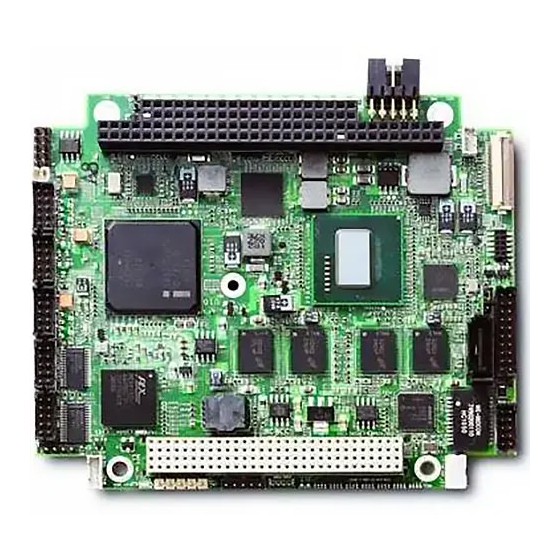
Page 10: Product Description
It can be stacked with ADLINK MiniModules™ or other PC/104-compliant expansion modules, or it can be used as a powerful computing engine. The CoreModule 720 requires a single +5V AT power source. -
Page 11: Module Features
Supports full modem capability on COM0 port ♦ Supports programmable baud-rate generator ♦ • COM0: 300bps to 4Mbps • COM1, 2, and 3: 300bps to 1Mbps • CAN Interface Supports bit rate up to 1 Mbps ♦ Supports 32 message objects ♦ CoreModule 720 Reference Manual... - Page 12 Power Button ♦ Reset Switch ♦ Speaker ♦ • Miscellaneous Real Time Clock (RTC) with external replaceable battery ♦ Battery-free boot ♦ Oops! Jumper support ♦ Serial Console support ♦ Watchdog Timer ♦ Logo Screen (Splash) ♦ Reference Manual CoreModule 720...
-
Page 13: Block Diagram
Chapter 2 Product Overview Block Diagram Figure 2-2 shows the functional components of the CoreModule 720. 4x DDR2 Memory Bus System Memory 1 4x DDR2 System Memory 2 LVDS Header Intel Atom E620T, E660T, or E680T SDVO SPI Flash (600MHz, 1.3GHz, or 1.6GHz) -
Page 14: Major Component (Ics) Definitions
Chapter 2 Product Overview Major Component (ICs) Definitions Table 2-1 lists the major ICs, including a brief description of each, on the CoreModule 720. Figures 2-3 show the locations of the major ICs. Table 2-1. Major Component Descriptions and Functions Chip Type Mfg. - Page 15 - on bottom side [see storage module through the Figure 2-4]) SATA interface Transformer - Wurth 7490200110 Gigabit Ethernet Provides Gigabit Ethernet Elektronik Magnetics electrical (T1) isolation for Gigabit Ethernet controller CoreModule 720 Reference Manual...
-
Page 16: Figure 2-3. Component Locations (Top Side)
U20 - SPI EEPROM - PCIe to PCI U32 - Thermal Regulator - PCIe to PCI U37 - Solid State Drive (SSD) - SATA - SD (Security Digital) Memory Card Socket (See Header, Connector, and Socket table) Figure 2-4. Component Locations (Bottom Side) Reference Manual CoreModule 720... -
Page 17: Header, Connector, And Socket Definitions
Chapter 2 Product Overview Header, Connector, and Socket Definitions Table 2-2 describes the headers, connectors, and socket of the CoreModule 720 shown in Figure 2-6. Table 2-2. Module Header and Connector Descriptions Header # Board Description Access J1 – LPC Debug 10-pin, 0.050"... -
Page 18: Figure 2-5. Connector Pin Sequences
Figure 2-6. Header, Connector, and Socket Locations (Top Side) NOTE Black square pins on headers and connectors represent pin 1. Black square pins on right-angle headers represent pin 2 in top-side views and pin 1 in bottom-side views. Reference Manual CoreModule 720... -
Page 19: Jumper Header Definitions
JP1 – Clear CMOS Enable Disable (Default) JP3 – LVDS Voltage Selection Enable +3.3V (1-2) (Default) Enable +5V (2-3) Key: JP1 - Clear CMOS JP3 - LVDS Voltage Select Figure 2-7. Jumper Header Locations (Top Side) CoreModule 720 Reference Manual... -
Page 20: Specifications
Chapter 2 Product Overview Specifications Physical Specifications Table 2-4 provides the physical dimensions of the CoreModule 720. Table 2-4. Weight and Footprint Dimensions NOTE Height is measured from the upper Item Dimension board surface to the highest permanent Weight 0.12 kg (0.25 lbs) -
Page 21: Mechanical Specifications
Figure 2-8. Mechanical Overview (Top Side) NOTE All dimensions are given in inches. Black square pins on headers and connectors represent pin 1. Black square pins on right-angle headers represent pin 2 in top-side views and pin 1 in bottom-side views. CoreModule 720 Reference Manual... -
Page 22: Power Specifications
Chapter 2 Product Overview Power Specifications Table 2-5 provides the power requirements for the CoreModule 720. Table 2-5. Power Supply Requirements Parameter 600MHz E620T 1.3GHz E660T 1.6GHz E680T Characteristics Characteristics Characteristics Input Type Regulated DC voltages Regulated DC voltages Regulated DC... -
Page 23: Thermal/Cooling Requirements
Chapter 2 Product Overview Thermal/Cooling Requirements The CPU is the primary source of heat on the board. The CoreModule 720 is designed to operate at the maximum speed of the CPU and requires a heatsink (provided). See Figure 2-9 for height measurements of the board and heatsink assembly. - Page 24 Chapter 2 Product Overview Reference Manual CoreModule 720...
-
Page 25: Chapter 3 Hardware
System Fan Interface • Battery Interface • Ethernet LED Interface • Miscellaneous SSD (SATA Solid State Drive) ♦ Time of Day/RTC ♦ Oops! Jumper (BIOS Recovery) ♦ Serial Console ♦ Hot Cable ♦ Watchdog Timer ♦ CoreModule 720 Reference Manual... -
Page 26: Cpu
Memory The CoreModule 720 employs two ranks of four system DRAM memory chips, which provide up to 2GB of extended memory, supporting aggressive power management to reduce power consumption, shallow self- refresh and a new deep self-refresh, proactive page closing policies to close unused pages, and partial writes through data mask pins. -
Page 27: Interrupt Channel Assignments
000A0000h 000AFFFFh Graphics Memory 000B0000h 000B7FFFh Mono Text Memory 000B8000h 000BFFFFh Color Text Memory 000C0000h 000CFFFFh Standard Video BIOS 000D0000h 000DFFFFh DVMT Memory 000E0000h 000EFFFFh PCI Express Base Memory 000F0000h 000FFFFFh System Flash and PCI Resources CoreModule 720 Reference Manual... -
Page 28: I/O Address Map
0A79h is the ISA PnP port used by the BIOS and an OS that supports this feature to recognize ISA PnP (Plug and Play) cards. The Intel I/O hub PCH EG20T does not support ISA DMA. Reference Manual CoreModule 720... -
Page 29: Serial Interfaces
Hardware Serial Interfaces The CoreModule 720 provides four RS-232 serial ports. The PCH EG20T contains the circuitry for all four serial ports and delivers the signals through two RS-232 transceivers: one transceiver for port COM0 and the second transceiver for ports COM1, COM2, and COM3. The serial ports support the following features: •... -
Page 30: Usb Interfaces
Ground Note: The shaded table cells denote ground. USB Interfaces The CoreModule 720 contains three root USB hubs and six functional USB ports. The PCH provides the USB function including the following features: • Supports USB v.2.0 EHCI and USB v.1.1 UHCI •... -
Page 31: Table 3-7. Usb2 And Usb3 Interface Pin Signals (J14)
CONN_USB5_N USB5 Port Data Negative CONN_USB4_P USB4 Port Data Positive CONN_USB5_P USB5 Port Data Positive USB_GND4 USB4 Ground USB_GND5 USB5 Ground USB_GND4 USB4 Ground USB_GND5 USB5 Ground Note: The shaded table cells denote power or ground. CoreModule 720 Reference Manual... -
Page 32: Ethernet Interface
Hardware Ethernet Interface The CoreModule 720 supports one Gigabit Ethernet interface. The Ethernet interface is implemented from the 82574IT Ethernet controller and provides oneGLAN interface, which occupies PCI Express port 2. The Ethernet function supports multi-speed operation at 10/100/1000 Mbps and operates in full-duplex at all supported speeds or half duplex at 10/100 Mbps while adhering to the IEEE 802.3x flow control... -
Page 33: Video (Sdvo/Lvds) Interfaces
SDVOB_BLU+ SDVO B BLUE Positive GND5 Ground 5 SDVOB_RED- SDVO B RED Negative SDVOB_RED+ SDVO B RED Positive GND6 Ground 6 SDVO_FLDSTALL- SDVO Input Field Stall Negative SDVO_FLDSTALL+ SDVO Input Field Stall Positive GND7 Ground 7 CoreModule 720 Reference Manual... -
Page 34: Table 3-11. Lvds Video Interface Pin Signals (J23)
LVDS A DATA Negative Line 0 LBKLT_CTL Panel Backlight Control LVDD_EN Enable Panel Power LDDC_CLK Display Data Channel Clock LDDC_DATA Display Data Channel Data LBKLT_EN Enable Backlight Inverter Not Connected Note: The shaded table cells denote power or ground. Reference Manual CoreModule 720... -
Page 35: Power Interface
Hardware Power Interface The CoreModule 720 requires one +5 volt DC power source and provides a shrouded 10-pin, right-angle header with 2 rows, odd/even pin sequence (1, 2), and 0.100" (2.54mm) pitch. If the +5VDC power drops below ~4.65V, a low voltage reset is triggered, resetting the system. -
Page 36: Utility Interface
External Power Button (Pins 1-2) Ground RESET SW* External Reset Switch signal (Pins 2-3) +5 Volts Power SPKR_CONN Speaker Output (Pins 4-5) Note: The shaded table cells denote power or ground. The * symbol indicates the signal is Active Low. Reference Manual CoreModule 720... -
Page 37: System Management Bus (Smbus)
CAN bus interface, which provides a 4-pin, single-row header with 0.079" (2mm) pitch. Table 3-17. CAN Interface Pin Signals (J4) Pin # Signal Description CAN_L Dominant Low CAN_H Dominant High +5 volts power Ground Note: The shaded table cells denote power or ground. CoreModule 720 Reference Manual... -
Page 38: I2C Interface
Hardware C Interface The CoreModule 720 provides a single-channel I2C interface, which conforms to version 2.1 of the I2C bus specification. The I2C controller resides on the EG20T PCH and operates as a master or slave device, supporting a multi-master bus. The following list highlights the features of the I2C bus interface. -
Page 39: Ethernet External Led
Real Time Clock (RTC) The CoreModule 720 contains a Real Time Clock (RTC). The RTC can be backed up with a battery. If the battery is not present, the board BIOS has a battery-less boot option to complete the boot process. -
Page 40: Serial Console
Hardware Serial Console The CoreModule 720 BIOS supports the serial console (or console redirection) feature. This I/O function is ANSI-compatible with a serial terminal or with equivalent terminal emulation software running on another system. This can be very useful when setting up the BIOS on a production line for systems that are not connected to a keyboard and display. -
Page 41: Chapter 4 Bios Setup
Entering BIOS Setup (Serial Port Console) This section describes how to enter the BIOS setup through a remote serial terminal or PC. Turn on the power supply to the CoreModule 720 and enter the BIOS Setup Utility using a local video display. -
Page 42: Oem Logo Utility
OEM Logo Utility The CoreModule 720 BIOS supports a graphical logo utility, which allows the user to customize the boot screen image. The graphical image can be a company logo or any custom image the user wants to display during the boot process. -
Page 43: Bios Setup Menus
BIOS Setup BIOS Setup Menus This section provides illustrations of the six main setup screens in the CoreModule 720 BIOS Setup Utility. Below each illustration is a bullet list of the screen’s submenus and setting selections. The setting selections are presented in brackets after each submenu or menu item, and the optimal default settings are presented in bold. -
Page 44: Advanced Bios Setup Screen
• PCI Latency Timer [32 PCI Bus Clocks; 64 PCI Bus Clocks; 96 PCI Bus Clocks; 128 PCI Bus Clocks; 160 PCI Bus Clocks; 192 PCI Bus Clocks; 224 PCI Bus Clocks; 248 PCI Bus Clocks] Reference Manual CoreModule 720... - Page 45 ♦ Limit CPUID Maximum [Disabled; Enabled] ♦ Intel Virtualization [Disabled; Enabled] ♦ C-States [Disabled; Enabled] ♦ Enhanced C1 [Disabled; Enabled] ♦ Enhanced C2 [Disabled; Enabled] ♦ Enhanced C3 [Disabled; Enabled] ♦ Enhanced C4 [Disabled; Enabled] ♦ CoreModule 720 Reference Manual...
- Page 46 Device reset time-out [10 sec; 20 sec; 30 sec; 40 sec] • Device power-up delay [Auto; Manual] • ADM1032 H/W Monitor CPU Health Status ♦ • CPU Temp : +XX • Serial Port Console Redirection COM0 (Pci Bus2, Dev10, Func1) ♦ • Console Redirection [Disabled; Enabled] Reference Manual CoreModule 720...
-
Page 47: Chipset Bios Setup Screen
Save & Exit ESC: Exit Version X.XX.XXXX. Copyright (C) 20XX American Megatrends, Inc. Figure 4-3. Chipset BIOS Setup Screen • North Bridge Chipset Configuration Memory Information ♦ • MRC Version XX.XX • Total Memory XXXX MB (DDR2) CoreModule 720 Reference Manual... - Page 48 1024x600 24bit; 1024x768 24bit; 1280x768 24bit] • South Bridge Chipset Configuration SMBUS Controller [Enabled; Disabled] ♦ High Precision Event Timer Configuration ♦ • High Precision Timer [Disabled; Enabled] PPM Config ♦ • C-state POPUP [Disabled; Enabled] Reference Manual CoreModule 720...
-
Page 49: Boot Bios Setup Screen
Boot Option #1 [P1-GLS85LS1032A CS 32GBN A101C0; Built -in EFI Shell; Disabled] ♦ Boot Option #2 [P1-GLS85LS1032A CS 32GBN A101C0; Built-in EFI Shell; Disabled] ♦ Hard Drive BBS Priorities ♦ • Boot Option #1 [P1-GLS85LS1032A CS 32GBN A101C0; Disabled] CoreModule 720 Reference Manual... -
Page 50: Security Bios Setup Screen
F4 : Save & Exit ESC: Exit Version X.XX.XXXX. Copyright (C) 20XX American Megatrends, Inc. Figure 4-5. Security BIOS Setup Screen • Password Description Administrator Password [Create New Password] ♦ User Password [Create New Password] ♦ Reference Manual CoreModule 720... -
Page 51: Save & Exit Bios Setup Screen
♦ • Reset without saving? [Yes; No] • Save Options Save Changes ♦ • Save configuration? [Yes; No] Discard Changes ♦ • Load Previous Values? [Yes; No] Restore Defaults ♦ • Load Optimized Defaults? [Yes; No] CoreModule 720 Reference Manual... - Page 52 Restore User Defaults? [Yes; No] • Boot Override P1-GLS85LS1032A CS 32GBN A101C0 ♦ • Save configuration and reset? [Yes; No] Built-in EFI Shell ♦ NOTE Selecting this setting enters the system into the EFI Shell mode screen. Reference Manual CoreModule 720...
-
Page 53: Appendix A Technical Support
Appendix A Technical Support ADLINK Technology, Inc. provides a number of methods for contacting Technical Support listed below in Table A-1. Requests for support through the Ask an Expert are given the highest priority, and usually will be addressed within one working day. - Page 54 Address: 84 Genting Lane #07-02A, Cityneon Design Centre, Singapore 349584 Tel: +65-6844-2261 Fax: +65-6844-2263 Email: singapore@adlinktech.com ADLINK Technology Singapore Pte. Ltd. (Indian Liaison Office) Address: No. 1357, "Anupama", Sri Aurobindo Marg, 9th Cross, JP Nagar Phase I, Bangalore - 560078, India Tel: +91-80-65605817 Fax: +91-80-22443548 Email: india@adlinktech.com...
-
Page 55: Index
Oops! jumper (BIOS recovery) ....6 jumper locations ..........13 optional system fan header ......32 PC/104 bus ............5 low voltage limit ..........29 PC/104-Plus bus ..........5 LVDS voltage ............. 13 reset switch ............30 SATA interface ..........5 CoreModule 720 Reference Manual... - Page 56 ..............6 Watchdog Timer ..........6 Watchdog Timer (WDT) ........34 System fan interface ..........32 web sites ............... 1 weight ..............14 Technical Support ..........47 thermal cooling processor requirements ........17 thickness .............. 14 Reference Manual CoreModule 720...
Need help?
Do you have a question about the CoreModule 720 and is the answer not in the manual?
Questions and answers