
Related Manuals for ADLINK Technology IMB-C46


Summary of Contents for ADLINK Technology IMB-C46
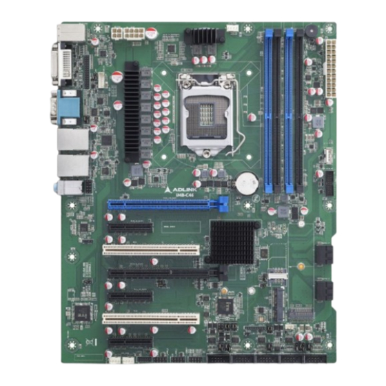
- Page 1 IMB-C46 User’s Manual ATX Motherboard with 10th/11th Gen Intel ® Core™ i9/i7/i5/i3 Processors and Intel Q470 Chipset ® Manual Rev.: 0.5 Preliminary Revision Date: October 8, 2024 Part Number: 50M-13017-1000...
-
Page 2: Environmental Responsibility
Preface Copyright Copyright 2024 ADLINK Technology, Inc. This document contains proprietary information protected by copyright. All rights are reserved. No part of this manual may be reproduced by any mechanical, electronic, or other means in any form without prior written permission of the manufacturer. -
Page 3: Revision History
IMB-C46 Revision History Revision Description Date Preliminary release 2024-07-03 Specs updated 2024-08-16 IO panel and onboard connector images and tables updated 2024-09-04 Specifications and connector pinouts updated 2024-10-04 Connector pinouts images added 2024-10-08 Preface... -
Page 4: Table Of Contents
Table of Contents Preface ..........................ii List of Figures ........................vi List of Tables ........................vi Introduction ........................ 1 Packing List ........................ 1 Optional Accessories ....................1 Specifications ......................3 Core System ....................... 3 I/O Interface ........................ 3 Video ........................... 4 Audio ........................... -
Page 5: Preface
IMB-C46 Save & Exit ....................... 47 Safety Instructions ......................48 Getting Services ....................... 49 Preface... - Page 6 List of Figures Figure 1: Functional Block Diagram ......................6 Figure 2: IO Panel Connector Locations ....................7 Figure 3: Onboard Connector – Header and Jumper Locations ..............8 Figure 4: Mechanical Dimensions ......................11 Figure 5: Mechanical Dimensions - IO Panel ..................11 List of Tables Table 1:IO Panel Connector Definitions ....................7 Table 2: Onboard Connector Definitions –...
-
Page 7: Introduction
It includes high-speed data transfer interfaces such as PCIe 3.0, USB 3.0, and SATA 6 Gb/s (SATA III), and quad-channel DDR4 2400/2666/2933 MHz RAM for industrial automation applications. With industrial-grade I/O port design, the IMB-C46 offers a significant competitive advantage for embedded computing applications in terms of device compatibility, durable connectivity, and extreme environment readiness. - Page 8 This page intentionally left blank. Introduction...
-
Page 9: Specifications
IMB-C46 2 Specifications 2.1 Core System CPU: Intel® Core™ i9-10900E, 4.7GHz, 10 Core, 20M Cache, DDR4 2933MHz support, 65W • • Intel® Core™ i9-10900TE, 4.5GHz, 10 Core, 20M Cache, DDR4 2933MHz support, 35W • Intel® Core™ i7-10700E, 4.5GHz, 8 Core, 16M Cache, DDR4 2933MHz support, 65W Intel®... -
Page 10: Video
COM: 1x RS-232/422/485 (by pin header) • • 1x RS-232/485 (by pin header) • 4x RS-232 (COM1 by DB9, others by pin headers) PS/2 Combo Port: 1x PS/2 keyboard/mouse pin header DIO: 8-bit GPIO Mini-PCIe slot: 1x Mini PCI-E Slot (WIFI+4G/3G, with 1x Full-Size SIM Card Slot) ... -
Page 11: Form Factor
IMB-C46 2.9 Form Factor ATX: 305 mm x 244 mm (W x L) 2.10 Operating Systems Microsoft® Windows® 10, 64-bit Specifications... -
Page 12: Functional Block Diagram
2.11 Functional Block Diagram Figure 1: Functional Block Diagram RJ45_USB1 (RJ45) I219-LM supports Intel AMT 12.0 and Intel vPro competent. RJ45_USB2 (RJ45) • supports I210 by default. • PCIEX16_SLOT1-2 slot support PCIE 16x or dual PCIE 8x is selected by ‘PCI-E Signal Select Jumper’ (J_PEG_CFG1). -
Page 13: Mechanical Layout
IMB-C46 3 Mechanical Layout 3.1 IO Panel Connector Locations Figure 2: IO Panel Connector Locations Table 1:IO Panel Connector Definitions Item Location Description PS/2_USB1 (PS/2) PS/2 Connector (Keyboard & Mouse) DVI_VGA1 (DVI-D) DVI-I 24+4P/F Connector (Support DVI-D) COM1 COM1 DB9/M Connector... -
Page 14: Figure 3: Onboard Connector - Header And Jumper Locations
32-2 31-2 32-1 31-1 23-1 (Lower) 23-2 (Upper) 23-3 (Lower) 23-4 (Upper) 14 15 16 9 10 11 12 13 8-2 8-3 Figure 3: Onboard Connector – Header and Jumper Locations Mechanical Layout... -
Page 15: Table 2: Onboard Connector Definitions - Header And Jumper Definitions
IMB-C46 Table 2: Onboard Connector Definitions – Header and Jumper Definitions Item Description Remarks SYS_FAN1 System FAN Header1 SYS_FAN2 System FAN Header2 J_GPIO1 GPIO Header F_USB2_2 Front USB2.0 Header2 F_USB2_1 Front USB2.0 Header1 F_PANEL1 Front Panel Header JP12 COM2 DCD/RI Select Jumper... - Page 16 31-1 DIMM2 DDR4 CHB DIMM Slot2 31-2 DIMM4 DDR4 CHB DIMM Slot4 32-1 DIMM1 DDR4 CHA DIMM Slot1 32-2 DIMM3 DDR4 CHA DIMM Slot3 CPU_FAN1 CPU FAN Header ATX2 ATX 8P CPU Power Input Connector ATX3 ATX 4P CPU Power Input Connector EDP_P1 eDP Backlight Control Header eDP VDD Select Jumper...
-
Page 17: Mechanical Dimensions
IMB-C46 3.2 Mechanical Dimensions Top View Dimensions: mm Figure 4: Mechanical Dimensions Side View Dimensions: mm Figure 5: Mechanical Dimensions - IO Panel Mechanical Layout... - Page 18 This page intentionally left blank. Mechanical Layout...
-
Page 19: Connector Pinouts
IMB-C46 4 Connector Pinouts See 3.1 Connector Locations on page 7 for connector locations. Rear IO Connectors 4.1.1 HDMI Signal Signal HDMI1_CON_DP2 HDMI1_CON_DN2 HDMI1_CON_DP1 HDMI1_CON_DN1 HDMI1_CON_DP0 HDMI1_CON_DN0 HDMI1_CON_CKP HDMI1_CON_CKN HDMI1_DDC_CLK HDMI1_DDC_DATA +5V_HDMI HDMI1_CON_HPD 4.1.2 VGA Connector Signal Signal VGA_CON_RED VGA_CON_GREEN... -
Page 20: Ethernet Connectors (Lan1, Lan2)
4.1.4 Ethernet Connectors (LAN1, LAN2) RJ45_USB2 (RJ45) * (GBE LAN RJ45 Connector2 8Pin) Signal Signal MDI0_2+ MDI2_2+ MDI0_2- MDI2_2- MDI1_2+ MDI3_2+ MDI1_2- MDI3_2- 1000M: Turn Orange ACT: Blinking Yellow LED1 Speed LED LED2 Active LED 100M: Turn Green Only LINK: Lights On 10M: Lights Off Stop: Lights Off Note: RJ45_USB2(RJ45) can support Wake-On-LAN. -
Page 21: Onboard Headers / Connectors
IMB-C46 4.2 Onboard Headers / Connectors 4.2.1 FAN Header (CPU_FAN1, SYS_FAN1, SYS_FAN2) Signal Description Ground +12 V FAN Power Tach FAN Tachometer FAN PWM 4.2.2 Front Panel Header (F_PANEL1) Signal Signal HDD 3.3V LED+ POWER 3.3V LED+ HDD 3.3V LED- POWER 3.3V LED-... - Page 22 RS485- RS485+ COM3 RS485 Note: [1] : When COM3 is RS232, PIN1 of COM3 can be DCD (default) /5V and Pin8 of COM3 can be RI(Default) /12V, selectable by “COM3 DCD/RI Select Jumper”. (JP8). [2]: COM3 can be RS232 (default) / RS422 / RS485 by selecting JP4, JP5, JP6. Signal Signal COM4_DCD [1]...
-
Page 23: Usb Connectors
IMB-C46 Definition Definition COM6_DCD [1] COM6_DSR COM6_RXD COM6_RTS COM6 RS232 COM6_TXD COM6_CTS COM6_DTR COM6_RI [1] Note: PIN1 of COM6 can be DCD (default) /5V and Pin8 of COM6 can be RI(Default) / 12V, selectable by “COM6 DCD/RI Select Jumper”. (JP11) 4.2.4... - Page 24 Signal Signal USB2_10+ 4.2.6 Front Panel Audio Header (F_AUDIO1) Signal Signal MIC_IN2_L GND_AUD MIC_IN2_R + 3.3V LINE_OUT2_R MIC2_RET GND_AUD LINE_OUT2_L LINE_OUT2_RET 4.2.7 ATX1 Signal Signal +3.3 V +3.3 V +3.3 V -12 V Ground Ground +5 V PS-ON# (power supply remote on/off) Ground Ground +5 V...
- Page 25 IMB-C46 4.2.9 ATX3 Signal Ground Ground +12V +12V 4.2.10 GPIO Header (J_GPIO1) Signal Signal SIO_GPI71 SIO_GPI70 (0xA06 Bit1, H) (0xA06 Bit0, H [1]) SIO_GPI73 SIO_GPI72 (0xA06 Bit3, H) (0xA06 Bit2, H) SIO_GPO74 (0xA06 Bit4, H) SIO_GPO76 SIO_GPO75 (0xA06 Bit6, H)
-
Page 26: Jumper And Switch Settings
4.2.13 SMBUS Header (SMBUS1) Signal Signal + 5V [1] SMB_DATA_MAIN SMB_CLK_MAIN 4.3 Jumper and Switch Settings 4.3.1 Clear CMOS Jumper (JP1) 4.3.2 COM1 DCD/RI Select Jumper (JP3) Setting Function COM1_PIN1: DCD 3-5, 2-4 COM1_PIN9: + 12V COM1_PIN1: + 5V 1-3, 4-6(Default) COM1_PIN9: RI 4.3.3 COM2 DCD/RI Select Jumper (JP12) - Page 27 IMB-C46 4.3.5 COM4 DCD/RI Select Jumper (JP9) Setting Function COM4_PIN1: DCD 3-5, 2-4 COM4_PIN8: + 12V COM4_PIN1: + 5V 1-3, 4-6(Default) COM4_PIN8: RI 4.3.6 COM5 DCD/RI Select Jumper (JP10) Setting Function COM5_PIN1: DCD 3-5, 2-4 COM5_PIN8: + 12V COM5_PIN1: + 5V...
- Page 28 4.3.9 COM3 RS232/485 Select Jumpers (JP4/JP5/JP6) Setting Function COM3: RS232 JP4 (1-2, Default) (COM3_PIN1: DCD JP5 (3-5, 4-6, Default) COM3_PIN3: RXD JP6 (3-5, 4-6, Default) COM3_PIN5: TXD COM3_PIN7: DTR) COM3: RS422 (COM3_PIN1: RS422_TX- JP4 (3-4) COM3_PIN3: RS422_TX+ JP5 (1-3, 2-4) COM3_PIN5: JP6 (1-3, 2-4) RS422_RX+...
- Page 29 IMB-C46 4.3.14 eDP Backlight Control Header (EDP_P1) Signal Signal EDP_BKLT_EN + 12V EDP_BKLT_CTL + 12V EDP_BKLT_EN 4.3.15 eDP Signal Header (EDP1) Signal Signal VDD_PANEL [1] VDD_PANEL [1] VDD_PANEL [1] EDP_HPD EDP_TX0- EDP_TX0+ EDP_TX1- EDP_TX1+ EDP_TX2- EDP_TX2+ EDP_TX3- EDP_TX3+ EDP_AUX- EDP_AUX+ Note: Panel Power VDD can be 3.3V (default) /5V selectable by eDP VDD Select Jumper”...
-
Page 30: Expansion Slots
4.3.17 PCIE Signal Select Jumper (J_PEG_CFG1) Setting Function PCIE_16X_SLOT1: PCIe 1-2 (Default) PCIE_16X_SLOT2: No resources Enable PCI CLK 66MHz 4.4 Expansion Slots There are 5 PCI Express slots, 2 PCI slots, 1 M.2 sockets, 1 mini-PCIe slot, and 1 SIM socket on this motherboard. PCIe and PCI slots: Slot 1 Slot 2... - Page 31 IMB-C46 M.2 sockets: M.2 Key-M (M_2_PCIESSD_M1) • Connector Pinouts...
- Page 32 This page intentionally left blank. Connector Pinouts...
-
Page 33: Driver Installation
IMB-C46 5 Driver Installation Download the requisite drivers for your system from the IMB-C46 product page at: https://www.adlinktech.com/Products/Industrial_Motherboards_SBCs/ATXMotherboards/IMB-C46 Driver Installation... - Page 34 This page intentionally left blank. Driver Installation...
-
Page 35: Bios Setup
IMB-C46 6 BIOS Setup 6.1 Menu Structure This section presents the primary menus of the BIOS (UEFI) Setup Utility. Use the following table as a quick reference for the contents of the UEFI Setup Utility. The subsections describe the submenus and options for each menu item. -
Page 36: Main Menu
6.2 Main Menu Upon entering the UEFI Setup Utility, the Main Menu is displayed, providing read-only information about your system and also allows you to set the System Date and Time. Refer to the screenshots and tables below for details of the submenus and settings. -
Page 37: Power And Performance
IMB-C46 6.3.2 Power and Performance Power and performance option. Feature Description CPU - Power CPU - Power Management Control Options. Management Control GT - Power Management GT - Power Management Control Options. Control 6.3.2.1 CPU-Power Management Control Feature... - Page 38 If this option is enabled, it activates the PL1 value to be used by the processor to limit the average power of a given time window. Platform PL2 Enable Enables or disables Platform Power Limit 2 programming. If this option is disabled, BIOS will program the default values for Platform Power Limit 2.
- Page 39 IMB-C46 Turbo Ratio Limit Core5 Turbo Ratio Limit Core5. This Turbo Ratio Limit Core5 must be less than Turbo Ratio (TRLC) Limit Core6. Turbo Ratio Limit Core6 Turbo Ratio Limit Core6. This Turbo Ratio Limit Core6 must be less than Turbo Ratio (TRLC) Limit Core7.
- Page 40 Core/IA VR Settings Core/IA VR Settings. GT VR Settings GT VR Settings. Intersil VR Command VR Mailbox command to fix Intersil VR C-state issues. Disabled- No Mailbox command sent. Default is Disabled. 6.3.2.1.2.1 Acoustic Noise Settings Feature Description Acoustic Noise Mitigation Enabling this option will help mitigate acoustic noise on certain SKUs when the CPU is in deeper C state.
- Page 41 IMB-C46 0x3. PS4 Enable Enable or Disable PS4. 0 - Disabled, 1 - Enabled. It uses the BIOS VR mailbox command 0x3. IMON Slope IMON Slope defined in 1/100 increments. Range is 0-200. For a 1.25 slope, enter 125. 0 = AUTO. It uses the BIOS VR mailbox command 0x4.
-
Page 42: Pch-Fw Configuration
6.3.3 PCH-FW Configuration Configure management engine technology parameters. Feature Description ME State When disabled, ME will be put into ME Temporarily disabled Mode. Firmware Update Configure Management Configuration 6.3.3.1 Firmware Update Configuration Feature Description ME FW Image Re-Flash Enables or disables ME FW Image Re-Flash function. FW Update Enables or disables ME FW Update function. -
Page 43: Super Io Configuration
IMB-C46 6.3.6 Super IO Configuration Feature Description COM1-6 Set Parameters of Serial Port 1-6. The options after entering the interface settings above are as follows. Serial Port: Enables or Disables Serial Port (COM). Device Settings: Displays the Current Device Settings. -
Page 44: Usb Configuration
Generally, due to differences in fan performance, the actual performance of smart fans may vary from the set value. It is generally recommended to set the PWM SLOPE SETTING to 8PWM to ensure that the fan speed adjusts appropriately with temperature changes. 6.3.8 OEM Flavor PXE boot LAN select. -
Page 45: Network Stack Configuration
IMB-C46 USB Mass Storage Driver Enables or disables USB Mass Storage Driver Support. Support USB Transfer Time-Out The time-out value for Control, Bulk, and Interrupt transfers. Device Reset Time-Out USB mass storage device Start Unit command time-out. Device Power-Up Delay Maximum time the device will take before it properly reports itself to the Host Controller. -
Page 46: Nvme Configuration
6.3.14 NVMe Configuration NVMe device option settings. Feature Description NVMe Devices Displays information about NVMe devices. Self-Test Option Select either short or extended self-test. Short option will take a couple of minutes and extended option will take several minutes to complete. Self-Test Action Select either to test controller alone or controller and namespace. - Page 47 IMB-C46 Row Hammer Solution Type of method used to prevent Row Hammer. RH Activation Probability Used to adjust MC for Hardware RHP. Refresh Watermarks Sets Refresh Panic Watermark and Refresh High-Profile Watermark to HIGH or LOW values. Exit On Failure (MRC) Exit On Failure for MRC training steps.
- Page 48 6.4.1.1.1.1 Memory Power and Thermal Throttling Feature Description DDR PowerDown and idle BIOS: BIOS is in control of DDR CKE mode and idle timer value. PCODE: pcode will counter manage the modes. For LPDDR Only: DDR For LPDDR Only: BIOS is in control of DDR CKE mode and idle timer value. PCODE: PowerDown and idle counter pcode will manage the modes.
- Page 49 IMB-C46 6.4.1.1.2 Memory Training Algorithms Feature Description Early Command Training Early Command Training. SenseAmp Offset Training SenseAmp Offset Training. Early ReadMPR Timing Enabled or disabled Early ReadMPR Timing. Centering 2D Read MPR Training Read MPR Training. Receive Enable Training Receive Enable Training.
-
Page 50: Pch-Io Configuration
Command Normalization Command Normalization. Early DQ Write Drive Early DQ Write Drive Strength and Equalization Training. Strength and Equalization Training Read Voltage Centering 1D Read Voltage Centering 1D. Dimm ODT CA Training Dimm ODT CA Training. Duty Cycle Correction Duty Cycle Correction. DQ DFE Training DQ DFE Training. -
Page 51: Security
IMB-C46 6.4.2.2 SATA and RST Configuration Feature Description SATA Controller(s) Enables or disables SATA device. SATA Mode Selection Determines how SATA controller(s) operate. Serial ATA Port X Port X: Enables or disables SATA port. 6.4.2.3 USB Configuration Feature Description XHCI Compliance Mode Option to enable Compliance mode. -
Page 52: Boot
To delete an administrator password, press the Carriage Return in the “Create New Password” window. Set/Change the User Password: 1) Select “Security - User Password.” 2) Enter the password you want to set in the “Create New Password” window and press Enter. You will need to confirm by entering the current password before accessing the “Create New Password”... -
Page 53: Save And Exit
IMB-C46 6.7 Save & Exit Feature Description Save Changes and Exit Exit system setup after saving the changes. Discard Changes and Exit system setup without saving any changes. Exit Save Changes and Reset Reset the system after saving the changes. -
Page 54: Safety Instructions
Safety Instructions Read and follow all instructions marked on the product and in the documentation before you operate your system. Retain all safety and operating instructions for future use. Please read these safety instructions carefully. • Please keep this User‘s Manual for later reference. •... - Page 55 6450 Via Del Oro, San Jose, CA 95119-1208, USA Tel: +1-408-360-0200 Toll Free: +1-800-966-5200 (USA only) Fax: +1-408-600-1189 Email: info@adlinktech.com ADLINK Technology (China) Co., Ltd. Address: 300 Fang Chun Rd., Zhangjiang Hi-Tech Park, Pudong New Area Shanghai, 201203 China Tel: +86-21-5132-8988 Fax: +86-21-5132-3588 Email: market@adlinktech.com...
Need help?
Do you have a question about the IMB-C46 and is the answer not in the manual?
Questions and answers