Table of Contents
Advertisement
Quick Links
Advertisement
Table of Contents

Subscribe to Our Youtube Channel
Related Manuals for ADLINK Technology CoreModule 745


Summary of Contents for ADLINK Technology CoreModule 745
- Page 1 ® CoreModule Single Board Computer Reference Manual P/N 50-1Z054-1020...
- Page 2 Notice Page DISCLAIMER ADLINK Technology, Incorporated makes no representations or warranties with respect to the contents of this manual or of the associated ADLINK products, and specifically disclaims any implied warranties of merchantability or fitness for any particular purpose. ADLINK shall under no circumstances be liable for incidental or consequential damages or related expenses resulting from the use of this product, even if it has been notified of the possibility of such damages.
-
Page 3: Table Of Contents
System Management Bus (SMBus)....................31 System Fan............................31 Battery............................32 Ethernet External LED ........................32 Miscellaneous ..........................32 SSD (Solid State Drive) ......................32 Real Time Clock (RTC) ......................32 Oops! Jumper (BIOS Recovery) ....................33 Remote Access ........................33 Remote Access Setup ......................33 Hot (Serial) Cable .......................33 CoreModule 745 Reference Manual... - Page 4 BIOS Exit Setup Screen......................44 Appendix A Technical Support ....................45 Index ..............................49 List of Figures Figure 2-1. Stacking PC/104-Plus Modules with the CoreModule 745 ........4 Figure 2-2. Functional Block Diagram ..................7 Figure 2-3. Component Locations (Top Side)................9 Figure 2-4.
- Page 5 Optional System Fan Pin Signals (J22) ..............31 Table 3-17. External Battery Input Header (J6) ...............32 Table 3-18. Ethernet External LED Pin Signals (J11) ...............32 Table 4-1. BIOS Setup Menus ....................37 Table A-1. Technical Support Contact Information..............45 CoreModule 745 Reference Manual...
- Page 6 Contents Reference Manual CoreModule 745...
-
Page 7: Chapter 1 About This Manual
• AMI BIOS Core 8 User’s Guide Web site: http://www.ami.com/support/doc/MAN-EZP-80.pdf Chip Specifications The following integrated circuits (ICs) are used in the CoreModule 745 single board computer: • Intel Corporation and the Atom™ N400 and D500 series processors Web site: http://www.intel.com/p/en_US/embedded/hwsw/hardware/atom-400-500/hardware •... - Page 8 Web site: http://www.iteusa.com http://www.ite.com.tw NOTE If you are unable to locate the datasheets using the links provided, go to the manufacturer’s web site where you can perform a search using the chip datasheet number or name listed. Reference Manual CoreModule 745...
-
Page 9: Chapter 2 Product Overview
The PC/104 architecture affords a great deal of flexibility in system design. You can build a simple system using only a CoreModule 745 SBC, input/output devices connected to the serial, USB, or SATA ports, and the on-board Solid State Disk storage device. To expand a simple CoreModule system, simply add self- stacking PC/104 and PC/104-Plus expansion boards to provide additional capabilities, such as: •... -
Page 10: Product Description
It can be stacked with ADLINK MiniModules™ or other PC/104-compliant expansion modules, or it can be used as a powerful computing engine. The CoreModule 745 requires a single +5V AT power source. -
Page 11: Module Features
Provides up to four USB ports Supports USB boot devices Supports USB v2.0 EHCI and v1.1 UHCI Supports over-current detection status • Keyboard/Mouse Interface Provides PS/2 keyboard interface Provides PS/2 mouse interface CoreModule 745 Reference Manual... - Page 12 D525 CPU) [single channel, three differential signals] • Utility Interface Power Button Reset Switch Speaker • Miscellaneous Battery-less boot Oops! Jumper support Remote Access support Watchdog Timer Logo Screen (Splash) Reference Manual CoreModule 745...
-
Page 13: Block Diagram
Chapter 2 Product Overview Block Diagram Figure 2-2 shows the functional components of the CoreModule 745. LVDS Memory Bus Intel Atom 1.67GHz DDR3 Video Header N455 or 1.83GHz D525 SODIMM PC/104-Plus Connector GPIO GPIO ISA Bus PCI to ISA Header... -
Page 14: Major Component (Ics) Definitions
Chapter 2 Product Overview Major Component (ICs) Definitions Table 2-1 lists the major ICs, including a brief description of each, on the CoreModule 745. Figures 2-3 show the locations of the major ICs. Table 2-1. Major Component Descriptions and Functions Chip Type Mfg. -
Page 15: Figure 2-3. Component Locations (Top Side)
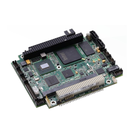
U1 - CPU U2 - ICH8-M (Southbridge) U4 - Gigabit Ethernet Controller U8 - PCI-to-ISA Bridge U9 - Super I/O U33 - SSD (Solid State Drive) T1 - Gigabit Ethernet Transformer Figure 2-3. Component Locations (Top Side) CoreModule 745 Reference Manual... -
Page 16: Header, Connector, And Socket Definitions
U38 - RS-232 Transceiver (COM3) U12 U11 Figure 2-4. Component Locations (Bottom Side) Header, Connector, and Socket Definitions Table 2-2 describes the headers and connectors of the CoreModule 745 shown in Figure 2-6. Table 2-2. Module Header, Connector, and Socket Descriptions Header #... -
Page 17: Figure 2-5. Connector Pin Sequences
2 is directly across from pin 1, is noted as 30-pin, 2 rows, odd/ even (1, 2) sequence. The second number in the parenthesis is always directly across from pin 1. See Figure 2-5. 30-pin, two rows, Odd/Even, (1, 2) Figure 2-5. Connector Pin Sequences CoreModule 745 Reference Manual... -
Page 18: Figure 2-6. Header, Connector, And Socket Locations (Top Side)
J24 - DDR3 SODIMM JP2 - LVDS Voltage Select (See jumper table) JP3 - Serial 2 RS-485/422 Termination (See jumper table) JP4 - Serial 1 RS-485/422 Termination (See jumper table) Figure 2-6. Header, Connector, and Socket Locations (Top Side) Reference Manual CoreModule 745... -
Page 19: Jumper Header Definitions
JP4 – Serial 1 RS-485/422 Enable Termination Disable Termination (Removed) Termination (Pins 1-2) [Default] Key: JP2 - LVDS Voltage Select JP3 - Serial 2 RS-485/422 Termination JP4 - Serial 1 RS-485/422 Termination Figure 2-7. Jumper Header Locations (Top Side) CoreModule 745 Reference Manual... -
Page 20: Specifications
Chapter 2 Product Overview Specifications Physical Specifications Table 2-4 provides the physical dimensions of the CoreModule 745. Table 2-4. Weight and Footprint Dimensions NOTE Overall height is measured from the Item Dimension upper board surface to the highest Weight 0.12 kg (0.25 lbs) -
Page 21: Mechanical Specifications
NOTE All dimensions are given in inches. Pin 1 is shown as a black square on headers and connectors. Black squares on right-angle headers indicate pin 2 in top-side views and pin 1 in bottom-side views. CoreModule 745 Reference Manual... -
Page 22: Power Specifications
Thermal/Cooling Requirements The CPU and PCH are the primary sources of heat on the board. The CoreModule 745 is designed to operate at the maximum speed of the CPU and requires various cooling solutions, depending on the CPU model. See Table 2-7 for descriptions of the cooling solution options. -
Page 23: Figure 2-9. Stack Height Of Cooling Assembly
Qualified to maintain optimal performance between -40°C and +85°C. (with fan) (Note: The D525 CPU requires an active heatsink for temperatures between +70°C and +85°C.) Copper Passive Heatsink 0.60 0.44 0.39 CoreModule 745 Aluminum Passive Heatsink 0.60 0.44 0.39 CoreModule 745 0.11 0.98 Active Heatsink 1.50... -
Page 24: Figure 2-10. Airflow Requirements
Chapter 2 Product Overview Figure 2-10. Airflow Requirements NOTE Airflow directions are from Top to Bottom. Reference Manual CoreModule 745... -
Page 25: Chapter 3 Hardware
• SMBus Interface • System Fan Interface • Battery Interface • Ethernet LED Interface • Miscellaneous SSD (IDE Solid State Drive) Time of Day/RTC Oops! Jumper Remote Access Watchdog Timer CoreModule 745 Reference Manual... -
Page 26: Cpu
Memory The CoreModule 745 supports one DDR3 SODIMM for up to 2GB of RAM. One 64-bit access channel supports single- or double-sided DIMMs, allowing for up to two device ranks. Enhanced memory technology on the board provides optimized bandwidth and reduced latency, increased efficiency of system memory protocol, and a near continuous data flow to the processor. -
Page 27: Interrupt Channel Assignments
000A0000h 000AFFFFh Graphics Memory 000B0000h 000B7FFFh Mono Text Memory 000B8000h 000BFFFFh Color Text Memory 000C0000h 000CFFFFh Standard Video BIOS 000D0000h 000DFFFFh DVMT Memory 000E0000h 000EFFFFh PCI Express Base Memory 000F0000h 000FFFFFh System Flash and PCI Resources CoreModule 745 Reference Manual... -
Page 28: I/O Address Map
0A79h is the ISA PnP port used by the BIOS and an OS that supports this feature to recognize ISA PnP (Plug and Play) cards. The Intel I/O hub ICH-8 (ICH-6 or later) does not support ISA DMA. Reference Manual CoreModule 745... -
Page 29: Serial Interfaces
Hardware Serial Interfaces The CoreModule 745 provides three serial ports: two RS-232/485/422 ports (COM1 and COM2) and one RS-232 port (COM3). The SCH3114I-NU SIO contains the circuitry for all three serial ports and delivers the signals through three transceivers. The two RS-232/485/422 ports require two transceivers: one ADM213EARSZ (U11) for RS-232 signals and one LTC1334CG (U12) for RS-485/422 signals. - Page 30 Used by software to initiate operations to answer and open the communications channel. Ground Key/NC Key Pin/Not connected Note: The shaded table cell denotes power or ground. The * symbol indicates the signal is Active Low. Reference Manual CoreModule 745...
-
Page 31: Usb Interface
Note: The shaded table cell denotes power or ground. The * symbol indicates the signal is Active Low. USB Interface The CoreModule 745 contains two root USB hubs and four functional USB ports. The ICH8-M provides the USB function including the following features: •... -
Page 32: Keyboard/Mouse Interface
Pin # Signal Description KEY VCC +5 Volts KEY DATA Keyboard data KEY CLK Keyboard clock KEY GND Keyboard ground KEY GND Keyboard ground KEY GND Keyboard ground KEY VCC +5 Volts CON DAT MOUSE Mouse data Reference Manual CoreModule 745... -
Page 33: Ethernet Interface
Note: The shaded table cells denote power or ground. Ethernet Interface The CoreModule 745 supports one Gigabit Ethernet interface. The Ethernet interface is implemented from the 82574IT Ethernet controller and provides one GLAN interface, which occupies PCI Express port 2. The Ethernet function supports multi-speed operation at 10/100/1000 Mbps and operates in full-duplex at all supported speeds or half duplex at 10/100 Mbps while adhering to the IEEE 802.3x flow control... -
Page 34: Video (Vga/Lvds) Interface
Digital to Analog Converter – Green Output to the CRT GREEN_RETURN VGA Ground for Green Output CON_DAC_BLUE Digital to Analog Converter – Blue Output to the CRT BLUE_RETURN VGA Ground for Blue Output CRT_HSYNC Horizontal Sync – Digital Horizontal Sync Output to the CRT Reference Manual CoreModule 745... -
Page 35: Power Interface
Note: The shaded table cells denote power or ground. Power Interface The CoreModule 745 requires one +5 volt DC power source and provides a shrouded 10-pin, right-angle header with 2 rows, odd/even pin sequence (1, 2), and 0.100" (2.54mm) pitch. If the +5VDC power drops below ~4.65V, a low voltage reset is triggered, resetting the system. -
Page 36: User Gpio Interface
Hardware User GPIO Interface The CoreModule 745 provides GPIO pins for customer use, routing the signals from the ICH8-M chipset to the J18 header. An example test application and source code reside in each BSP directory of the CoreModule 745 Support Software QuickDrive. -
Page 37: System Management Bus (Smbus)
System Fan header, which provides 3 pins with 0.079" (2mm) pitch. Table 3-16. Optional System Fan Pin Signals (J22) Pin # Signal Description +5.0 volts DC +/- 5% Not Connected Ground Note: The shaded table cells denote power or ground. CoreModule 745 Reference Manual... -
Page 38: Battery
Real Time Clock (RTC) The CoreModule 745 contains a Real Time Clock (RTC). The RTC can be backed up with a battery. If the battery is not present, the board BIOS has a battery-less boot feature to complete the boot process. -
Page 39: Oops! Jumper (Bios Recovery)
Figure 3-2. Oops! Jumper Serial Port (DB9) Remote Access The CoreModule 745 BIOS supports Remote Access (or console redirection). This I/O function can be utilized through an ANSI-compatible serial terminal or the equivalent terminal emulation software running on another system. This can be very useful when setting up the BIOS on a production line for systems that are not connected to a keyboard and display. -
Page 40: Watchdog Timer
Support Software QuickDrive illustrating how to control the WDT. The code examples can be easily copied to your development environment to compile and test the examples, or make any desired changes before compiling. Refer to the WDT Readme file on the CoreModule 745 Support Software QuickDrive. -
Page 41: Chapter 4 Bios Setup
This section describes how to enable the Remote Access in VGA mode and enter the BIOS setup through a serial terminal or PC. Turn on the power supply to the CoreModule 745 and enter the BIOS Setup Utility in VGA mode. Set the BIOS feature Remote Access to [Enabled] under the Advanced menu. -
Page 42: Pci-Isa Bridge Mapping
IRQs from “Available” to “Reserved”. OEM Logo Utility The CoreModule 745 BIOS supports a graphical logo utility, which can be customized by the user and displayed when enabled through the BIOS Setup Utility. The graphical image can be a company logo or any custom image the user wants to display during the boot process. -
Page 43: Bios Setup Menus
BIOS Setup BIOS Setup Menus This section provides illustrations of the six main setup screens in the CoreModule 745 BIOS Setup Utility. Below each illustration is a bullet list of the screen’s submenus and setting selections. The setting selections are presented in brackets after each submenu or menu item and the optimal default settings are presented in bold. -
Page 44: Bios Advanced Setup Screen
Enhanced C-States [Disabled; Enabled] - (Available only on the N455 model) • Chipset Configuration North Bridge Chipset Configuration • PCIMMIO Allocation: XGB to XXXXMB • DRAM Frequency [Auto; Max MHz] • Configure DRAM Timing by SPD [Enabled; Disabled] Reference Manual CoreModule 745... - Page 45 Serial Port1 IRQ [3; 4; 10; 11] • RS-485 Control for SP1 [Disabled; Enabled] Serial Port2 Address [Disabled; 2F8; 3E8; 2E8] • Serial Port2 IRQ [3; 4; 10; 11] • RS-485 Control for SP2 [Disabled; Enabled] CoreModule 745 Reference Manual...
- Page 46 VT-VTF8 Combo Key Support [Disabled; Enabled] Sredir Memory Display Delay [No Delay; Delay 1 Sec; Delay 2 Sec; Delay 4 Sec] • Watchdog Timer Configuration Watchdog Timer [Disabled; Enabled] • GPIO Configuration GPOs Configuration Reference Manual CoreModule 745...
-
Page 47: Bios Power Management Setup Screen
ACPI APIC Support [Disabled; Enabled] • APIC ACPI SCI IRQ [Disabled; Enabled] • High Performance Event Timer [Disabled; Enabled] • HPET Memory Address [FED00000h; FED01000h; FED02000h; FED03000h] Hardware Health Configuration • CPU Temperature XX°C / XXX°F CoreModule 745 Reference Manual... -
Page 48: Bios Boot Setup Screen
4th Boot Device [Removable Dev; CD/DVD; HDD: SM-XGB NANDrive; USB; Network; Disabled] 5th Boot Device [Removable Dev; CD/DVD; HDD: SM-XGB NANDrive; USB; Network; Disabled] Hard Disk Drives • 1st Drive [SATA: SM-XGB NANDri; Disabled] Reference Manual CoreModule 745... -
Page 49: Bios Security Setup Screen
Exit CM745_BIOS_Security_a VXX.XX (C) Copyright 1985-20XX, American Megatrends, Inc. Figure 4-5. BIOS Security Setup Screen • Security Settings Supervisor Password [Not Installed] User Password [Not Installed] Change Supervisor Password Change User Password CoreModule 745 Reference Manual... -
Page 50: Bios Exit Setup Screen
Discard Changes (F7 key can be used for this operation.) Load Optimal Defaults (F9 key can be used for this operation.) Load Failsafe Defaults (F8 key can be used for this operation.) Reference Manual CoreModule 745... -
Page 51: Appendix A Technical Support
Appendix A Technical Support ADLINK Technology, Inc. provides a number of methods for contacting Technical Support listed below in Table A-1. Requests for support through the Ask an Expert are given the highest priority, and usually will be addressed within one working day. - Page 52 84 Genting Lane #07-02A, Cityneon Design Centre, Singapore 349584 Tel: +65-6844-2261 Fax: +65-6844-2263 Email: singapore@adlinktech.com ADLINK Technology Singapore Pte. Ltd. (Indian Liaison Office) Address: 1st Floor, #50-56 (Between 16th/17th Cross) Margosa Plaza, Margosa Main Road, Malleswaram, Bangalore-560055, India Tel: +91-80-65605817, +91-80-42246107 Fax: +91-80-23464606 Email: india@adlinktech.com...
- Page 53 Appendix A Technical Support Table A-1. Technical Support Contact Information (Continued) ADLINK Technology, Inc. (Israeli Liaison Office) Address: 6 Hasadna St., Kfar Saba 44424, Israel Tel: +972-9-7446541 Fax: +972-9-7446542 Email: israel@adlinktech.com CoreModule 745 Reference Manual...
- Page 54 Appendix A Technical Support Reference Manual CoreModule 745...
-
Page 55: Index
Remote Access ............33 Exit setup screen ..........44 reset switch header pin outs ..........30 features ..............5 supported feature ...........30 RS-485 mode ..........23 GPIO features ............30 Security setup screen ...........43 pin signals ............. 30 CoreModule 745 Reference Manual... - Page 56 IRQ assignments ........... 21 source code examples ........34 jumpers on board ........... 13 web sites ............... 1 memory map ..........21 weight ..............14 Oops! jumper (BIOS recovery) ....6 width ..............14 optional system fan header ......31 Reference Manual CoreModule 745...
Need help?
Do you have a question about the CoreModule 745 and is the answer not in the manual?
Questions and answers