
Subscribe to Our Youtube Channel
Related Manuals for ADLINK Technology CoreModule 430


Summary of Contents for ADLINK Technology CoreModule 430
-
Page 1: Reference Manual
CoreModule (PC/104 Single Board Computer) Reference Manual P/N 50-1Z006-1010... - Page 2 CoreModule and the Ampro logo are registered trademarks, and ADLINK, Little Board, LittleBoard, MightyBoard, MightySystem, MilSystem, MiniModule, ReadyBoard, ReadyPanel, ReadySystem, and RuffSystem are trademarks of ADLINK Technology, Inc. All other marks are the property of their respective companies. REVISION HISTORY...
-
Page 3: Table Of Contents
Speaker ............................24 Ethernet Interface .........................25 Video (TTL/VGA) Interface ......................26 Serial Peripheral Interface (SPI) ....................28 Low Pin Count Interface (LPC) ......................28 Miscellaneous ..........................28 Real Time Clock (RTC) ......................28 User GPIO Interface ........................29 Oops! Jumper (BIOS Recovery) ....................29 CoreModule 430 Reference Manual... - Page 4 BIOS Exit Setup Screen......................45 Appendix A Technical Support ....................47 Index ..............................49 List of Figures Figure 2-1. Stacking PC/104 Modules with the CoreModule 430 ..........3 Figure 2-2. Block Diagram ......................7 Figure 2-3. Component Locations (Top Side)................9 Figure 2-4.
- Page 5 SPI Interface Pin/Signal Descriptions (J19) ............28 Table 3-14. LPC Interface Pin/Signal Descriptions (J20)............28 Table 3-15. User GPIO Interface Pin/Signal Descriptions (J8) ..........29 Table 3-16. Power Interface Pin/Signals (J7)................31 Table 4-1. BIOS Setup Menus ....................35 Table A-1. Technical Support Contact Information..............47 CoreModule 430 Reference Manual...
- Page 6 Contents Reference Manual CoreModule 430...
-
Page 7: Chapter 1 About This Manual
For latest revision of the PC/104 specifications, contact the PC/104 Consortium, at: Web site: http://www.pc104.org Major Integrated Circuit (Chip) Specifications The following chip specifications are used in the CoreModule 430 processor module: • DMP Electronics Inc. and the Vortex 86SX/DX CPU Web site: http://www.vortex86sx.com/... - Page 8 Chapter 1 About This Manual Reference Manual CoreModule 430...
-
Page 9: Chapter 2 Product Overview
• Analog or digital I/O interfaces PC/104 expansion modules can be stacked with the CoreModule 430 avoiding the need for card cages and backplanes. The PC/104 expansion modules can be mounted directly to the PC/104 bus connector of the CoreModule 430. PC/104-compliant modules can be stacked with an inter-board spacing of ~0.66" (16.7 mm) so that a 3-module system fits in a 3.6"... -
Page 10: Product Description
These enhancements ensure fail-safe embedded system operation, such as a watchdog timer. The CoreModule 430 is designed to meet the size, power consumption, temperature range, quality, and reliability demands of embedded applications. The CoreModule 430 requires a single +5V power source. - Page 11 Provides hardware command queue Supports all BLT transparency modes • Bitmap transparency • Pattern transparency • Source transparency • Destination transparency Supports rectangle clipping Supports fast line draw engine with styled pattern CoreModule 430 Reference Manual...
- Page 12 Provides General Purpose I/O (GPIO) interface Supports Oops! Jumper (BIOS Recovery) Supports Remote Access (Console Redirection) Supports customizable Splash Screen Supports Watchdog Timer (WDT) Provides 16 Mbits of virtual floppy drive capacity Reference Manual CoreModule 430...
-
Page 13: Block Diagram
Header Header Transceiver (X1) Compact Flash 44-Pin IDE COM1 & COM2 RS422/485 Socket Header Header Transceiver (X1) Parallel (LPT) Ethernet 10/100 Ethernet Header Transformer Header Utility Interface Header Header GPIOs (8) Header Figure 2-2. Block Diagram CoreModule 430 Reference Manual... -
Page 14: Major Components (Ics)
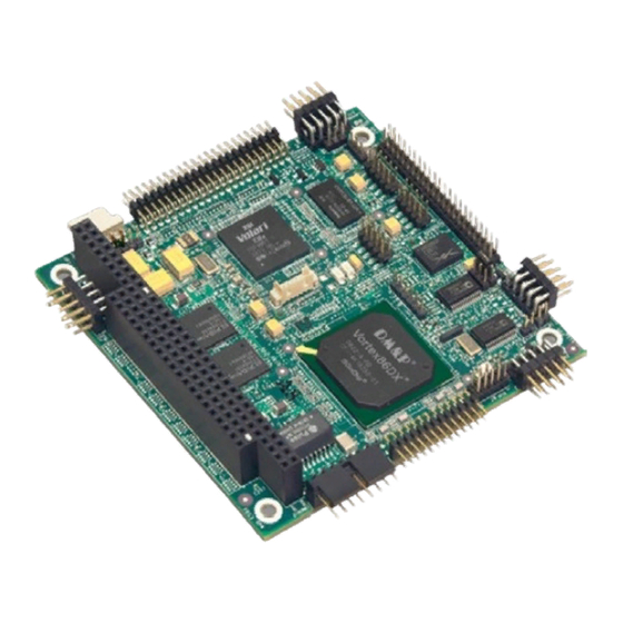
Chapter 2 Product Overview Major Components (ICs) Table 2-1 describes the major integrated circuits (ICs) on the CoreModule 430, and Figure 2-3 shows the locations of the major ICs on the board. Table 2-1. Major Components (Chips) Descriptions and Functions Chip Type Mfg. -
Page 15: Figure 2-3. Component Locations (Top Side)
U14 - DDR2 SDRAM - Video Memory Figure 2-3. Component Locations (Top Side) NOTE Pin 1 is shown as a black pin (square or round) on vertical headers or connectors in all illustrations. Black dots on right-angle headers or connectors indicate pin CoreModule 430 Reference Manual... -
Page 16: Header, Connector, And Socket Definitions
11 is directly across from pin 1, is noted in this way: 20-pin, 2 rows, consecutive (1, 11). The second number in the parenthesis is always directly across from pin 1. See Figure 2-4. 20-pin, two rows, 20-pin, two rows, Odd/Even, (1, 2) Consecutive, (1, 11) Figure 2-4. Connector Pin Identifications Reference Manual CoreModule 430... -
Page 17: Jumper Header Definitions
+5 Volts (Pins 1-2) +3.3 Volts (Pins 2-3) Default Voltage Select JP8 – IDE Select Enable HDD master, CF slave (Pins 1-2) Enable HDD slave, CF master Default (Pins 2-3) Note: All jumper headers use 0.079" (2mm) pitch. CoreModule 430 Reference Manual... -
Page 18: Specifications
10.99mm (0.43") (PC/104 connector) on the See Note on page upper board surface. This does not include the heatsink. Width 90.2mm (3.6") Length 95.9mm (3.8") Mechanical Specifications 3.775 3.575 0.200 Figure 2-6. Mechanical Dimensions (Top Side) Reference Manual CoreModule 430... -
Page 19: Power Specifications
Thermal/Cooling Requirements The CPU is the primary source of heat on the board. The 800 MHz version of the CoreModule 430 CPU is designed to operate at its maximum speed and requires a heatsink (provided). The 300 MHz version of the CoreModule 430 CPU does not require a heatsink. - Page 20 Chapter 2 Product Overview Reference Manual CoreModule 430...
-
Page 21: Chapter 3 Hardware
Mouse Battery Reset Switch Speaker • Ethernet • • Video • • • Miscellaneous Time of Day/RTC User GPIO Oops! Jumper (BIOS Recovery) Watchdog timer • Power CoreModule 430 Reference Manual... -
Page 22: Cpu
• SPI Flash System Memory The CoreModule 430 provides two 16-bit, DDR2 memory chips of up to 128MB each for a total of up to 256MB of system memory soldered to the module and operating at 166MHz. Video Memory The CoreModule 430 provides one 16-bit, DDR2 memory chip of 32MB of video memory soldered to the module and operating at 166MHz. -
Page 23: Memory Map
Reserved for Extended BIOS 000E0000h 000EFFFFh Extended System BIOS Area 000F0000h 000FFFFFh System BIOS Area (Storage and RAM Shadowing) 00100000h Top of Main DRAM Range DRAM FFFC0000h FFFFFFFFh System Flash [for SX processor] FFE00000h [for DX processor] CoreModule 430 Reference Manual... -
Page 24: Interrupt Channel Assignments
BIOS Plug and Play logic. Local IRQs assigned during initialization can not be used by external devices. Table 3-3. DMA Map DMA # 0-1, 5, 6, 7 Direct Memory Access LPT 1, only in ECP mode (configurable) DMA 1 cascade Reference Manual CoreModule 430... -
Page 25: I/O Address Map
Serial Port 3 (COM3) (base configuration @ 3F8h/2F8h/3E8h/2E8h/10) 03F6 IDE 0 (see 1F0) 03F8-03FF Serial Port 1 (COM1) (base configuration @ 3F8h/2F8h/3E8h/2E8h/10) 0778-077A LPT 1 (only in EPP modes, with default base address) 0CF8 PCI Configuration Address 0CFC-0CFF PCI Configuration Data CoreModule 430 Reference Manual... -
Page 26: Parallel Interface (Lpt)
Select – This is a status output signal from the printer. A High State indicates it is selected and powered on. Key/NC Key Pin/Not Connected Note: The shaded table cells denote power or ground. The * symbol indicates the signal is Active Low. Reference Manual CoreModule 430... -
Page 27: Serial Interface
Hardware Serial Interface The Vortex CPU contains the circuitry for all four serial ports. The CoreModule 430 provides serial ports 1 and 2 through transceivers U7 and U9 (headers J3 and J9), serial port 3 through transceiver U4 (header J14) and serial port 4 through transceiver U5 (header J13). -
Page 28: Table 3-6. Serial Ports 1 & 2 Interface Pin/Signal Descriptions (J3, J9)
Receive Data – Serial port receive data input is typically held at a logic 1 (mark) when no data is being transmitted, and is held “Off” for a brief interval after an “On” to “Off” transition on the RTS line to allow the transmission to complete. Reference Manual CoreModule 430... -
Page 29: Usb Interface
Note: The shaded table cell denotes ground. The * symbol indicates the signal is Active Low. USB Interface The CoreModule 430 contains one root USB (Universal Serial Bus) hub and two functional USB ports. The Vortex CPU provides the USB function including the following features: •... -
Page 30: Utility Interface
Table 3-10. Utility Interface Pin/Signal Descriptions (J5) Pin # Signal Description SPKR Speaker Output BATV- Ground return RESETSW* External Reset Switch signal MDATA Mouse Data input KBDATA Keyboard Data input KBCLK Keyboard Clock input Ground KMPWR Keyboard /Mouse power (+5V) output Reference Manual CoreModule 430... -
Page 31: Ethernet Interface
Center Tap – Connected through two 75 ohm resistors in series to center tap of isolation transformer and then to ground through common 1k PF capacitor. NOTE The magnetics (isolation transformer, U12) for the Ethernet connector is included on the CoreModule 430. CoreModule 430 Reference Manual... -
Page 32: Video (Ttl/Vga) Interface
Panel Data 2 – These pins (0 to 23) provides digital pixel data output signals. Panel Data 3 – Refer to pin 9, FP2, for more information. Panel Data 4 – Refer to pin 9, FP2, for more information. Reference Manual CoreModule 430... - Page 33 AGNDB Analog Ground for Blue BLUE Blue – This pin provides the Blue analog output to the CRT. Note: The shaded table cells denote power or ground. The * symbol indicates the signal is Active Low. CoreModule 430 Reference Manual...
-
Page 34: Serial Peripheral Interface (Spi)
Miscellaneous Real Time Clock (RTC) The CoreModule 430 contains a Real Time (time of day) Clock (RTC), which can be backed up with an external cell battery. The CoreModule 430 will function without a battery in those environments which prohibit batteries. The CoreModule 430 will also continue to operate after the battery life has been exceeded. -
Page 35: User Gpio Interface
Hardware User GPIO Interface The CoreModule 430 provides GPIO pins for customer use, and the signals are routed to header J8. An example of how to use the GPIO pins resides in the Miscellaneous Source Code Examples on the CoreModule 430 Support Software QuickDrive. -
Page 36: Remote Access
PC with communications software. The BIOS Setup Utility controls the remote access settings on the CoreModule 430. Refer to Chapter 4, BIOS Setup for the settings of the remote access option, the serial terminal, or PC with communications software and the connection procedure. -
Page 37: Power Interface
Hardware Power Interface The CoreModule 430 requires one +5 volt DC power source. If the +5VDC power drops below ~4.65V, a low voltage reset is triggered, resetting the system. The power input header (J7) supplies the following voltages and ground directly to the module: •... - Page 38 Chapter 3 Hardware Reference Manual CoreModule 430...
-
Page 39: Chapter 4 Bios Setup
This section describes how to enable the Remote Access in VGA mode and enter the BIOS setup through a serial terminal or PC. Turn on the power supply to the CoreModule 430 and enter the BIOS Setup Utility in VGA mode. Set the BIOS feature Remote Access Configuration to [Enable] under the Advanced menu. -
Page 40: Oem Logo Utility
OEM Logo Utility The CoreModule 430 BIOS supports a graphical logo utility, which can be customized by the user and displayed when enabled through the BIOS Setup Utility. The graphical image can be a company logo or any custom image the user wants to display during the boot process. The custom image can be displayed as the first image displayed on screen during the boot process and remain there, depending on the options selected in BIOS Setup, while the OS boots. -
Page 41: Bios Setup Screens
BIOS Setup BIOS Setup Screens This section provides illustrations of the seven main setup screens in the CoreModule 430 BIOS Setup Utility. Below each illustration is a bullet list of the screen’s submenus and setting selections. The setting selections are presented in brackets after each submenu or menu item and the optimal default settings are presented in bold. -
Page 42: Bios Advanced Setup Screen
OnBoard PCI IDE Controller – [Disabled; Primary; Secondary; Both] Primary IDE Master : [Not Detected] • Type – [Not Installed; Auto; CD/DVD; ARMD] • LBA/Large Mode – [Disabled; Auto] • Block (Multi-Sector Transfer – [Disabled; Auto] Reference Manual CoreModule 430... - Page 43 Sredir Memory Display Delay – [No Delay; Delay 1 sec; Delay 2 sec; Delay 4 sec] USB Configuration • USB Port 0, 1 – [Enabled; Disabled] • USB Port 2, 3 – [Enabled; Disabled] • USB Device – [Enabled; Disabled] CoreModule 430 Reference Manual...
-
Page 44: Bios Pcipnp Setup Screen
• Plug & Play O/S – [No; Yes] • PCI Latency timer – [32; 64; 96; 128; 160; 192; 224; 248] • Allocate IRQ to PCI VGA – [Yes; No] • Palette Snooping – [Disabled; Enabled] Reference Manual CoreModule 430... - Page 45 • DMA Channel 3 – [Available; Reserved] • DMA Channel 5 – [Available; Reserved] • DMA Channel 6 – [Available; Reserved] • DMA Channel 7 – [Available; Reserved] • Reserved Memory – [Disabled; 16k; 32k; 64k] CoreModule 430 Reference Manual...
-
Page 46: Bios Boot Setup Screen
Interrupt 19 Capture – [Disabled; Enabled] • Boot From LAN – [Disabled; Used INT 18h; Used INT 19h; PnP/BEV (BBS); RPL] • Beep Function – [Disabled; Enabled] • OnBoard Virtual Flash FDD – [Disabled; Enabled; Diskette Write Protect] Reference Manual CoreModule 430... -
Page 47: Bios Security Setup Screen
If the password is not confirmed when you re-type it, an error message will appear. The password is stored in NVRAM if you have successfully entered the password. • Boot Sector Virus Protection – [Disabled; Enabled] CoreModule 430 Reference Manual... -
Page 48: Bios Chipset Setup Screen
P.O.S.T. Forward To [Disabled; COM1] ISA Configuration • ISA Clock – [8.3MHz; 16.6MHz] • ISA 16bits I/O wait-state – [1 clock; 2 clock; 3 clock; 4 clock; 5 clock; 6 clock; 7 clock; 8 clock] Reference Manual CoreModule 430... - Page 49 Port0 Bit0 Direction – [IN; OUT] • Port0 Bit1 Direction – [IN; OUT] • Port0 Bit2 Direction – [IN; OUT] • Port0 Bit3 Direction – [IN; OUT] • Port0 Bit4 Direction – [IN; OUT] • Port0 Bit5 Direction – [IN; OUT] CoreModule 430 Reference Manual...
- Page 50 - Direction – [IN; OUT] • Port3 Bit5 Function – [GPIO] - Direction – [IN; OUT] • Port3 Bit6 Function – [GPIO; I2C] - Direction – [IN; OUT] • Port3 Bit7 Function – [GPIO] - Direction – [IN; OUT] Reference Manual CoreModule 430...
-
Page 51: Bios Exit Setup Screen
Discard Changes Load Optimal Defaults Load Failsafe Defaults Select Screen Select Item Enter Go to Sub Screen General Help Save and Exit Exit x02.xx (C) Copyright 1985-20xx, American Megatrends, Inc. Figure 4-7. BIOS Exit Setup Screen CoreModule 430 Reference Manual... - Page 52 The < F7 > key can be used for this operation. Load Optimal Defaults The < F9 > key can be used for this operation. Load Failsafe Defaults The < F8 > key can be used for this operation. Reference Manual CoreModule 430...
-
Page 53: Appendix A Technical Support
Appendix A Technical Support ADLINK Technology, Inc. provides a number of methods for contacting Technical Support listed in the Table A-1 below. Requests for support through the Ask an Expert are given the highest priority, and usually will be addressed within one working day. - Page 54 Address: 84 Genting Lane #07-02A, Cityneon Design Centre, Singapore 349584 Tel: +65-6844-2261 Fax: +65-6844-2263 Email: singapore@adlinktech.com ADLINK Technology Singapore Pte. Ltd. (Indian Liaison Office) Address: No. 1357, "Anupama", Sri Aurobindo Marg, 9th Cross, JP Nagar Phase I, Bangalore - 560078, India Tel: +91-80-65605817 Fax: +91-80-22443548 Email: india@adlinktech.com...
-
Page 55: Index
Exit BIOS setup screen ........45 PC/104 architecture ............3 floppy, virtual ............. 16 interface ............4 PCIPnP BIOS setup screen ........38 GPIO interface description and pin signals ..29 power graphics controller ........16 interface pin-out ..........31 requirements ..........13 CoreModule 430 Reference Manual... - Page 56 ......... 13 Vortex CPU ............4 memory ............4 memory map ..........17 Watchdog Timer (WDT) ........30 mouse ............24 web site Oops! jumper (BIOS recovery) ....6 ADLINK ............47 references ............1 weight ..............12 Reference Manual CoreModule 430...
Need help?
Do you have a question about the CoreModule 430 and is the answer not in the manual?
Questions and answers