
Related Manuals for ADLINK Technology NuPRO-935A


Summary of Contents for ADLINK Technology NuPRO-935A
- Page 1 NuPRO-935A Full-Sized PICMG 1.0 SBC Intel® Q35/ICH9 Chipset User’s Manual Manual Rev.: 2.04 Revision Date: April 26, 2011 Part No: 50-13060-1030 Advance Technologies; Automate the World.
-
Page 2: Revision History
Revision History Revision Release Date Description of Change(s) 2.00 2008/08/29 Initial release 2.01 2008/10/29 Correct Board Layout (COM1/2) Update OS support, driver locations, add TPM 2.02 2009/05/13 driver installation Correct BIOS Power Button Mode description; correct CPU Fan connector, GbE connector, Floppy connector pin definitions;... -
Page 3: Preface
NuPRO-935A Preface Copyright 2008-2011 ADLINK Technology Inc. This document contains proprietary information protected by copy- right. All rights are reserved. No part of this manual may be repro- duced by any mechanical, electronic, or other means in any form without prior written permission of the manufacturer. - Page 4 Using this Manual Audience and Scope The NuPRO-935A User’s Manual is intended for hardware technicians and systems operators with knowledge of installing, configuring and operating industrial grade single board computers. Manual Organization This manual is organized as follows: Preface: Presents important copyright notifications, disclaimers, trademarks, and associated information on the proper understand- ing and usage of this document and its associated product(s).
- Page 5 NuPRO-935A Conventions Take note of the following conventions used throughout this manual to make sure that users perform certain tasks and instructions properly. Additional information, aids, and tips that help users perform tasks. NOTE: NOTE: Information to prevent minor physical injury, component dam- age, data loss, and/or program corruption when trying to com- plete a task.
- Page 6 This page intentionally left blank. Preface...
-
Page 7: Table Of Contents
NuPRO-935A Table of Contents Revision History..............ii Preface ..................iii List of Figures ................ xi List of Tables................ xiii 1 Introduction ................ 1 Overview................1 Features................1 Specifications............... 2 Power Consumption ............4 Block Diagram ..............5 Functional Description ............6 Mechanical Drawing ............ - Page 8 4 Driver Installation.............. 37 Intel® Q35 Express Chipset Driver ........37 Display Driver..............38 LAN Driver ................. 38 ISA Driver................39 TPM Driver................. 39 Audio Driver ............... 40 5 BIOS Setup ................ 41 Starting the BIOS ............... 41 Main Setup................. 45 Advanced BIOS Setup ............
- Page 9 NuPRO-935A A Appendix: Watchdog Timer..........73 Sample Code ..............73 B Appendix: System Resources.......... 77 System Memory Map............77 Direct Memory Access Channels........78 IO Map ................79 Interrupt Request (IRQ) Lines..........81 Important Safety Instructions ..........87 Getting Service..............89...
- Page 10 This page intentionally left blank. Table of Contents...
-
Page 11: List Of Figures
NuPRO-935A List of Figures Figure 1-1: NuPRO-935A Block Diagram .......... 5 Figure 1-2: NuPRO-935A Board Dimensions (top view)....9 Figure 2-1: Rear Panel I/O Ports............13 Figure 2-2: Connectors and Jumpers Pt. 1 ........16 Figure 2-3: Connectors and Jumpers Pt. 2 ........17... - Page 12 This page intentionally left blank. List of Figures...
-
Page 13: List Of Tables
NuPRO-935A List of Tables Table 1-1: NuPRO-935A General Specifications......3 Table B-1: System Memory Map............. 77 Table B-2: Direct Memory Access Channels........78 Table B-3: IO Map ................80 Table B-4: IRQ Lines PIC Mode............81 Table B-5: IRQ Lines APIC Mode ........... 83 Table B-6: PCI Interrupt Request Routing........ - Page 14 This page intentionally left blank. List of Tables...
-
Page 15: Introduction
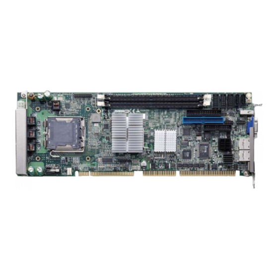
NuPRO-935A Introduction 1.1 Overview The ADLINK NuPRO-935A is a PICMG 1.0 industrial SBC supporting the next-generation Intel® Core 2 Quad/Duo and Intel® Celeron® processors in the LGA775 package to deliver a high performance platform for a wide array of industrial automation applications. -
Page 16: Specifications
Hardware • CPU/System temperature, fan speed and Monitor onboard DC voltage • Infineon SLB 9635 TT 1.2 (NuPRO-935A/DV only) I/O Interfaces • One-channel UDMA 33, ATA-66/100 support • One 40-pin IDE connector (1 device only) Serial ATA •... -
Page 17: Table 1-1: Nupro-935A General Specifications
• 338 x 122 mm (L x W) Operating Temp. • 0ºC to 60ºC Storage Temp. • -20ºC to 80ºC • 5% to 90% non-condensing both operating and Relative Humidity non-operating Safety • CE, FCC Class A Table 1-1: NuPRO-935A General Specifications Introduction... -
Page 18: Power Consumption
1.4 Power Consumption Test Configuration Intel® Core 2 Quad processor Q6600 2.40 GHz Memory Transcend DDR2 800 1GB x2 Graphics Intel ® 82Q35 Graphics Memory controller SATA Channel Seagate ST3808110AS Barracuda 7200.9 80GB Power Supply COOLMAX FL-480ATX 450W DOS (idle) Power Req. -
Page 19: Block Diagram
USB 2.0 33MHz bus (Bracket x1, Internal x4) Controller Codec IT8888G ISA bus ISA Bridge (DV only) Header for DB-Audio2 KB/Mouse SPI BIOS LPT/FDD ITE8718 LPC Super I/O Hardware RS-232 Monitor RS-232/ 422/485/ 485+ Figure 1-1: NuPRO-935A Block Diagram Introduction... -
Page 20: Functional Description
1.6 Functional Description Processor Support The NuPRO-935A is a single processor design for the latest Intel Yorkfield/Wolfdale/Conroe Processor family, starting from 1.8 GHz core frequency with future option up to 3.0 GHz. With one LGA775 socket, the CPU connects with Intel Q35 MCH through the 800/1066/1333 MHz Front Side Bus (FSB). - Page 21 Serial ATA II technology Storage is efficient and secure with the Serial ATA II interface. Uti- lizing the Intel® ICH9, the NUPRO-935A supports up to two Serial ATA II devices capable of reading/writing data at up to 3 Gbps. The SATA specification improves chassis airflow via thinner and more flexible cables with lower pin count.
- Page 22 Trusted Platform Module The NuPRO-935A optionally supports TPM ver. 1.2 (Trusted Plat- form Module) for secure storage of keys, passwords and digital certificates. Systems supporting TPM offer improved hard-...
-
Page 23: Mechanical Drawing
NuPRO-935A 1.7 Mechanical Drawing Figure 1-2: NuPRO-935A Board Dimensions (top view) Introduction... -
Page 24: I/O Connectivity
1.8 I/O Connectivity Golden Bracket Onboard Remarks Finger USB1 — — — — DB-15 GbE1 (RJ-45) Y (with LED Act/Link/Speed — — indication) GbE2 (RJ-45) Y (with LED Act/Link/Speed — — indication) PS/2 KB/MS1* — — — KB/MS — — 2.54 pitch USB2/3 —... -
Page 25: Package Contents
See “PS/2 Keyboard/Mouse Port” on page 14 for more information. NOTE: NOTE: The NuPRO-935A must be protected from static discharge and physical shock. Never remove any of the socketed parts except at a static-free workstation. Use the anti-static bag shipped with WARNING: the product to handle the board. - Page 26 This page intentionally left blank. Introduction...
-
Page 27: Hardware Information
NuPRO-935A Hardware Information This chapter provides information on the NuPRO-935A board lay- out, connector pin assignments, and jumper settings. 2.1 Rear Panel I/O Ports Figure 2-1: Rear Panel I/O Ports Connector Description PS/2 KB/MS port Connects a PS/2 mouse and keyboard... - Page 28 PS/2 Keyboard/Mouse Port Pin # Signal Function KBDAT Keyboard Data MSDAT Mouse Data Ground KBMS5V Power KBCLK Keyboard Clock MSCLK Mouse Clock For boards without a Mini-DIN PS/2 KB/MS con- nector, customers wishing to use a PS/2 type keyboard and mouse may purchase a PS/2 cable with bracket (P/N: 30-01019-2000) which connects to the External Keyboard/Mouse Con- nector (CN19).
- Page 29 NuPRO-935A LAN (RJ-45) Ports 10BASE- Pin # 1000BASE-T T/100BASE-TX BI_DA+ BI_DA- BI_DB+ BI_DC+ BI_DC- BI_DB- BI_DD+ BI_DD- Refer to the table below for the LAN port LED indications. ACT/LINK LED SPEED LED Status Description Status Description No Link 10 Mb connection...
-
Page 30: Vga Port
VGA Port Pin # Signal Green Blue Ground Ground Ground Ground +5 V Ground DDC DAT HSYNC VSYNC DDC CLK Hardware Information... -
Page 31: Board Layout
NuPRO-935A 2.2 Board Layout The illustrations below show the locations of connectors, slots, and jumpers on the NuPRO-935A. Figure 2-2: Connectors and Jumpers Pt. 1 Connector Description DIMM1 240-pin DDR2 DIMM slot DIMM2 240-pin DDR2 DIMM slot System Panel connector... - Page 32 13 14 Figure 2-3: Connectors and Jumpers Pt. 2 Connector Description HD Audio Daughter Board connector COM2 connector COM1 connector Serial ATA connector Serial ATA connector Floppy port connector CN10 IDE connector CN11 USB1 pin header CN12 USB2 pin header CN13 LPT connector COM1 mode jumper...
-
Page 33: Onboard Connectors
NuPRO-935A 2.3 Onboard Connectors ATX 12V Power Connector (CN7) Pin # Signal +12V DC +12V DC The ATX 12V power connector must be connected to provide sufficient power to the SBC in either ATX or AT modes . See “Installing the Power Connectors” on page 34. - Page 34 IDE Connector (CN10) Pin # Signal Pin # Signal Reset IDE Ground Host data 7 Host data 8 Host data 6 Host data 9 Host data 5 Host data 10 Host data 4 Host data 11 Host data 3 Host data 12 Host data 2 Host data 13 Host data 1...
- Page 35 NuPRO-935A Floppy disk drive connector (CN8) Pin # Signal Pin # Signal Extended Density Index Motor A Select Drive A Select Step Direction Step Pulse Write Data Write Gate Track 0 Write Protect Read Data Side 1 Disk Change Hardware Information...
- Page 36 Parallel Port (CN13) Pin # Signal Pin # Signal Line Printer Strobe Auto-Feed Parallel Data 0 Error Parallel Data 1 Initialize Parallel Data 2 Select Parallel Data 3 Ground Parallel Data 4 Ground Parallel Data 5 Ground Parallel Data 6 Ground Parallel Data 7 Ground...
- Page 37 NuPRO-935A COM1 Connector (RS-422/485/485+) (CN6) Pin # Signal Functions Transmit (-) Not Connected Transmit (+) Not Connected Receive (+) Not Connected Receive (-) Not Connected Ground Not Connected Note: See Section 2.4 for COM1 mode jumper settings. COM1/COM2 Connector (RS-232) (CN5/6)
- Page 38 USB 2.0 Connector (CN11-12) Pin # Signal Pin # Signal USB0- USB1- USB0+ USB01+ External Keyboard/Mouse Connector (CN19) Pin # Signal Function KDAT Keyboard data KCLK Keyboard clock MDAT Mouse data MCLK Mouse data P5V_KM +5 V Ground For use with PS/2 cable with bracket (P/N: 30-01019-2000). Serial ATA Connectors (CN2-3) Pin # Signal...
- Page 39 NuPRO-935A System Panel Connector (CN1) Connects to chassis-mounted buttons, speakers, and LEDs. Pin # Signal Function Pin Group Power for +5v Power LED HC_PLED- Power LED signal Ground Ground ATX Power ATX_PSO Power-on signal for Connector P5V_SB_A Power for +5v...
-
Page 40: Jumpers
The CMOS RAM data contains the date / time and BIOS setting information. CMOS is powered by the onboard button cell battery. To erase the CMOS RAM data: (1) Unplug the NuPRO-935A (2) short the JP1 pin 2-3 (3) turn the power on. After power on, remove the jumper cap from pin 2-3 and reinstall it to pin 1-2. -
Page 41: Getting Started
This chapter provides information on how to install components on the NuPRO-935A SBC. 3.1 Installing the CPU The NuPRO-935A supports a single Intel® Core™2 Quad/Duo, Pentium® D, or Celeron® processor via the surface mount LGA775 socket (Socket T). Disconnect all power supply to the board before installing a CPU to prevent damaging the board and CPU. - Page 42 2. Lift and rotate the load lever to a 135° angle 3. Lift the load plate to a 100° angle using your thumb and forefinger 4. Use your thumb to push and remove the protective socket cover (plastic) from the load plate Getting Started...
- Page 43 NuPRO-935A 5. Position the CPU over the socket, then match the notches on the CPU side with the alignment keys on the socket. The golden triangle on the CPU must be posi- tioned on the bottom-left corner of the socket .
- Page 44 7. Close the load plate (A), then fasten the load lever on the retention tab (B) . Getting Started...
-
Page 45: Installing The Cpu Fan And Heatsink
CPU. The following CPU fan and heatsink assemblies are recom- mended for use with the NuPRO-935A: 1U LGA 775 CPU Cooler Dimensions: • Heatsink: 92 x 87.6 x 28 mm •... - Page 46 CPU Fan/Heatsink Installation When the CPU fan/heatsink installation procedures presented here are inconsistent with the installation procedures included with the CPU fan and heatsink package, follow the latter. To install the CPU fan/heatsink: 1. Attach the backplate included with the fan/heatsink to the bottom side of the SBC.
- Page 47 NuPRO-935A 4. Connect the CPU fan cable to the CPU fan connector on the SBC labeled FAN2 (see “Board Layout” on page 16). Note: Do not use fan/heatsinks with push-pin type attachments. They may exert too much tension on the PCB and cause the board to flex, resulting in damage to the SBC.
-
Page 48: Installing The Power Connectors
ATX 12V Power Connector The NuPRO-935A requires +12V DC power connected to CN7 for proper operation in either ATX or AT modes . If necessary, order a ATX12V Convert Cable from ADLINK for use with Molex 4-pin power connectors (P/N 30-00006-0000). -
Page 49: Installing Memory Modules
NuPRO-935A 3.4 Installing Memory Modules The NuPRO-935A supports up to 4 GB of DDR2 800/667 MHz memory modules in two DDR2 DIMM sockets. A DDR2 module has a 240-pin footprint compared to the legacy 184-pin DDR DIMM. DDR2 modules are notched to facilitate correct installation on the DIMM sockets. - Page 50 3. Align the memory module on the socket making sure that the notch matches the break on the socket. Notch Break 4. Insert the module firmly into the slot until the retaining clips snap back inwards and the module is securely seated.
-
Page 51: Driver Installation
NuPRO-935A Driver Installation This chapter provides information on how to install the NuPRO-935A device drivers under Windows XP/Vista. The device drivers are located in the following ADLINK All-in-One DVD directories: Chipset Driver \NuPRO\NuPRO-935A\Chipset\ Display Driver \NuPRO\NuPRO-935A\VGA\ LAN Driver \NuPRO\NuPRO-935A\Ethernet\ ISA Driver... -
Page 52: Display Driver
Media Accelerator (GMA) 3000 driver. To install the display driver: 1. Locate the display driver from this directory X:\NuPRO\NuPRO-935A\VGA\, then double-click on the Setup.exe file to start installation. 2. Follow screen instructions to complete installation, then restart the system if prompted. -
Page 53: Isa Driver
(Advanced)’ and then click ‘Next’. 6. Locate the following folder on the ADLINK All-in-One DVD: X:\NuPRO\NuPRO-935A\ISA. Press ‘Next’ to install the inf files. 7. After successfully installing the files, the ‘Hardware Update Wizard’ will display the ‘Completing the Hard- ware Update Wizard’... -
Page 54: Audio Driver
4.6 Audio Driver Follow these instructions to install the audio driver for the optional DB-Audio2 daughter board. Before installing the audio driver, check the BIOS set- tings to make sure that audio is enabled: Chipset > South Bridge Configurations > HDA Controller (see NOTE: NOTE: Section 5.7.1). -
Page 55: Bios Setup
NuPRO-935A BIOS Setup The following chapter describes basic navigation for the AMIBIOS®8 BIOS setup utility. 5.1 Starting the BIOS To enter the setup screen, follow these steps: 1. Power on the system 2. Press the < Delete > key on your keyboard when you see the following text prompt: <... - Page 56 Setup Menu The main BIOS setup menu is the first screen that you can navi- gate. Each main BIOS setup menu option is described in this user’s guide. The Main BIOS setup menu screen has two main frames. The left frame displays all the options that can be configured.
- Page 57 NuPRO-935A Note: There is a hot key legend located in the right frame on most setup screens. The < F8 > key on your keyboard is the Fail-Safe key. It is not dis- played on the key legend by default. To set the Fail-Safe settings of the BIOS, press the <...
- Page 58 The < F10 > key allows you to save any changes you have made and exit Setup. Press the < F10 > key to save your changes. The following screen will appear: Press the < Enter > key to save the configuration and exit. You can also use the <...
-
Page 59: Main Setup
NuPRO-935A 5.2 Main Setup When you first enter the Setup Utility, you will enter the Main setup screen. You can always return to the Main setup screen by select- ing the Main tab. There are two Main Setup options. They are described in this section. -
Page 60: Advanced Bios Setup
5.3 Advanced BIOS Setup Select the Advanced tab from the setup screen to enter the Advanced BIOS Setup screen. You can select any of the items in the left frame of the screen, such as SuperIO Configuration, to go to the sub menu for that item. You can display an Advanced BIOS Setup option by highlighting it using the <... -
Page 61: Cpu Configuration
NuPRO-935A 5.3.1 CPU Configuration You can use this screen to select options for the CPU Configura- tion Settings. Use the up and down < Arrow > keys to select an item. Use the < + > and < - > keys to change the value of the selected option. -
Page 62: Ide Configuration
5.3.2 IDE Configuration You can use this screen to select options for the IDE Configuration Settings. Use the up and down < Arrow > keys to select an item. Use the < + > and < - > keys to change the value of the selected option. -
Page 63: Floppy Configuration
NuPRO-935A 5.3.3 Floppy Configuration You can use this screen to specify options for the Floppy Configu- ration Settings. Use the up and down < Arrow > keys to select an item. Use the < + > and < - > keys to change the value of the selected option. -
Page 64: Super Io Configuration
5.3.4 Super IO Configuration You can use this screen to select options for the Super IO settings. Use the up and down < Arrow > keys to select an item. Use the < + > and < - > keys to change the value of the selected option. The settings are described on the following pages. - Page 65 NuPRO-935A if Serial Port1 uses 3F8/IRQ4, the option, the 3F8/IRQ4 will not appear in the options of Serial Port2. Parallel Port Mode This option specifies the parallel port mode. Normal: Set this value to allow the standard parallel port mode to be used.
-
Page 66: Hardware Health Configuration
5.3.5 Hardware Health Configuration This option displays the current status of all of the monitored hard- ware devices / components such as voltages and temperatures. BIOS Setup... -
Page 67: Remote Access Configuration
NuPRO-935A 5.3.6 Remote Access Configuration Remote access configuration provides the settings to allow remote access by another computer to get POST messages and send commands through serial port access. Remote Access Select this option to Enable or Disable the BIOS remote access feature. - Page 68 Serial Port Mode Select the baud rate you want the serial port to use for console redirection. The options are 115200 8,n,1; 57600 8,n,1; 19200 8,n,1; and 09600 8,n,1. Flow Control Set this option to select Flow Control for console redirection. The settings for this value are None, Hardware, or Software.
-
Page 69: Trusted Computing
NuPRO-935A 5.3.7 Trusted Computing Trusted computing is an industry standard to make personal com- puters more secure through a dedicated hardware chip, called a Trusted Platform Module (TPM). This option enables or disables the TPM support. BIOS Setup... -
Page 70: Usb Configuration
5.3.8 USB Configuration You can use this screen to select options for the USB Configura- tion. Use the up and down < Arrow > keys to select an item. Use the < + > and < - > keys to change the value of the selected option. - Page 71 NuPRO-935A there are no USB drivers loaded on the system. Set this value to enable or disable the Legacy USB Support. Disabled: Set this value to prevent the use of any USB device in DOS or during system boot. Enabled: Set this value to allow the use of USB devices during boot and while using DOS.
- Page 72 USB Mass Storage Device Configuration This is a submenu for configuring the USB Mass Storage Class Devices when BIOS finds they are in use on USB ports. Emula- tion Type can be set according to the type of attached USB mass storage device(s).
-
Page 73: Advanced Pci/Pnp Settings
NuPRO-935A 5.4 Advanced PCI/PnP Settings Select the PCI/PnP tab from the setup screen to enter the Plug and Play BIOS Setup screen. You can display a Plug and Play BIOS Setup option by highlighting it using the < Arrow > keys. The Plug and Play BIOS Setup screen is shown below. -
Page 74: Isa Plug And Play
5.4.2 ISA Plug and Play This setting enables/disables the ISA Plug and Play functionality. BIOS Setup... -
Page 75: Boot Settings
NuPRO-935A 5.5 Boot Settings Select the Boot tab from the setup screen to enter the Boot BIOS Setup screen. You can select any of the items in the left frame of the screen, such as Boot Device Priority, to go to the sub menu for that item. - Page 76 Quick Boot Enabling this setting will cause the BIOS power-on self test routine to skip some of its tests during bootup for faster system boot. Quiet Boot When this feature is enabled, the BIOS will display the full- screen logo during the boot-up sequence, hiding normal POST messages.
-
Page 77: Boot Device Priority
NuPRO-935A 5.5.2 Boot Device Priority The items allow you to set the sequence of boot devices where BIOS attempts to load the disk operating system. First press <Enter> to enter the sub-menu. Then you may use the arrow keys to select the desired device, then press <+>, <-> or <PageUp>, <PageDown>... -
Page 78: Security Setup
5.6 Security Setup Password Support Two Levels of Password Protection Provides both a Supervisor and a User password. If you use both passwords, the Supervisor password must be set first. The system can be configured so that all users must enter a password every time the system boots or when Setup is exe- cuted, using either or either the Supervisor password or User password. - Page 79 NuPRO-935A Remember the Password Keep a record of the new password when the password is changed. If you forget the password, you must erase the sys- tem configuration information in NVRAM. To access the sub menu for the following items, select the item and press <...
- Page 80 and press < Enter >. If the password confirmation is incorrect, an error message appears. The password is stored in NVRAM after completes. Change User Password Select Change User Password from the Security Setup menu and press < Enter >. Enter New Password: Type the password and press <...
-
Page 81: Chipset Setup
NuPRO-935A 5.7 Chipset Setup Select the Chipset tab from the setup screen to enter the Chipset BIOS Setup screen. You can select any of the items in the left frame of the screen to go to the sub menu for that item. The Chipset BIOS Setup screen is shown below. -
Page 82: South Bridge Configuration
5.7.1 South Bridge Configuration You can use this screen to select options for the South Bridge Configuration. Use the up and down <Arrow> keys to select an item. Use the <Plus> and <Minus> keys to change the value of the selected option. -
Page 83: Advanced Chipset Settings
NuPRO-935A 5.7.2 Advanced Chipset Settings ACPI Aware O/S This option specifies which OS support ACPI. The options are Enabled and Disabled. Resume On PME# This option specifies if the PME#. event will generate a system wake event. The sub-options are Enabled and Disabled. -
Page 84: Exit Menu
5.8 Exit Menu Select the Exit tab from the setup screen to enter the Exit BIOS Setup screen. You can display an Exit BIOS Setup option by high- lighting it using the < Arrow > keys. The Exit BIOS Setup screen is shown below. - Page 85 NuPRO-935A Discard Changes and Exit Select this option to quit Setup without making any permanent changes to the system configuration. Discard Changes and Exit Setup Now? [Ok] [Cancel] appears in the window. Select Ok to discard changes and exit. Discard Changes Select Discard Changes from the Exit menu and press <...
- Page 86 This page intentionally left blank. BIOS Setup...
-
Page 87: A Appendix: Watchdog Timer
NuPRO-935A Appendix A - Watchdog Timer A sample program for configuring the NuPRO-935A’s watchdog timer is included on the ADLINK All-in-One DVD in the following directory: \NuPRO\NuPRO-935A\WDT. A.1 Sample Code #include<stdlib.h> #include<stdio.h> #include<string.h> #include<dos.h> void WDTRUN(int config_port,int count_value); void Enter_IT8718_Config(int config_port);... - Page 88 0x21); DevID2 = inportb(ioport+1); if((DevID1 == 0x87) && (DevID2 == 0x18)) chipflag = 1; if(chipflag == 0) printf("ADLINK Watchdog Timer Utility of NuPRO-935A\n\n"); printf("Can't find any ITE IT8718F on system!\n"); Exit_IT8718_Config(ioport); exit(1); else printf("ADLINK Watchdog Timer Utility of NuPRO-935A\n\n");...
- Page 89 NuPRO-935A outportb(0x2E, 0x87); outportb(0x2E, 0x01); outportb(0x2E, 0x55); outportb(0x2E, 0x55); break; case 0x4E: //Address port = 0x4E, enter keys = 0x87, 0x01, 0x55, 0xAA outportb(0x2E, 0x87); outportb(0x2E, 0x01); outportb(0x2E, 0x55); outportb(0x2E, 0xAA); break; default: break; void Exit_IT8718_Config(int config_port) outportb(config_port, 0x02); outportb(config_port+1, 0x02);...
- Page 90 else if(count_value <= 60){ temp = temp | 0x80;//chip's default is minute. counter = count_value; printf("WDT timeout in %d seconds.",counter); temp = temp | 0x40;//enable WDT output through KBRST temp = temp | 0x10;//enable WDT output through PWROK2 (pulse) outportb(config_port+1, temp); } // end of (count_value<=60) else if(((count_value>60) &&...
-
Page 91: B Appendix: System Resources
NuPRO-935A Appendix B System Resources B.1 System Memory Map Address Range Address Range Size Description (decimal) (hex) FFE00000 – (4GB-2MB) 2 MB High BIOS Area FFFFFFFF (4GB-18MB) – FEE00000 – 1 MB FSB Interrupt Memory Space (4GB-17MB-1) FEEFFFFF (4GB-20MB) –... -
Page 92: Direct Memory Access Channels
B.2 Direct Memory Access Channels Channel Number Data Width System Resource 8-bits Parallel port 8-bits Parallel port 8-bits Diskette drive 8-bits Parallel port Reserved - cascade channel 16-bits Open 16-bits Open 16-bits Open Table B-2: Direct Memory Access Channels Note (1): DMA channel 0/1/3 is selected when using parallel port. Floppy and parallel port cannot be used at the same time. -
Page 93: Io Map
NuPRO-935A B.3 IO Map Hex Range Device 000-01F DMA controller 1, 8237A-5 equivalent 020-02D and 030- Interrupt controller 1, 8259 equivalent 02E-02F LPC SIO (ITE8718) configuration index/data registers 040-05F Timer, 8254-2 equivalent 060, 062, 064, 066, 8742 equivalent (keyboard) 068-06F... -
Page 94: Table B-3: Io Map
Hex Range Device 278-27F Parallel Port 2 280-2F7 Available 2F8-2FF Serial Port 2 300-36F Available 370-377 Alt. Floppy Disk Controller 378-37F Parallel Port 1 380-3AF Available 3B0-3BB and 3BF Mono/VGA mode video 3BC-3BE Reserved for parallel port 3C0-3DF VGA registers 3E0-3EF Available 3F0-3F7... -
Page 95: Interrupt Request (Irq) Lines
NuPRO-935A B.4 Interrupt Request (IRQ) Lines IRQ Lines PIC Mode Typical Interrupt IRQ# Connected to Pin Available Resource Counter 0 Keyboard controller Cascade interrupt from slave PIC Serial Port 2 (COM2) / IRQ3 via SERIRQ, IRQ3 Note (1) PCI / ISA... - Page 96 IRQ Lines APIC Mode Typical Interrupt IRQ# Connected to Pin Available Resource Counter 0 Keyboard controller Cascade interrupt from slave PIC Serial Port 2 (COM2) / IRQ3 via SERIRQ, Note (1) PCI / ISA IRQ3 at ISA bus Serial Port 1 (COM1) / IRQ4 via SERIRQ, Note (1) PCI / ISA...
-
Page 97: Table B-5: Irq Lines Apic Mode
NuPRO-935A Typical Interrupt IRQ# Connected to Pin Available Resource PCI Slot 1/2/3/4, PCIE Port 0/1/2/3/4/5 UHCI Controller 3, PEG Root Port, SATA Host controller, SMBus Controller, Thermal Controller, EHCI Controller #2 PCI Slot 1/2/3/4, PCIE Port 0/1/2/3/4/5 UHCI Controller 2/7, PEG Root... -
Page 98: Pci Interrupt Request Routing
PCI Interrupt Request Routing Bus # Device # Function # Routing Description Intel 965 GME GMCH Host-Hub Interface Bridge Internal PEG. Root Port 0FFH PEG. Port Internal Intel Integrated Graphics Device Intel Integrated Graphics Device Internal (Function 1) Internal GbE Controller Internal Intel USB UHCI Controller 4 Internal... -
Page 99: Table B-6: Pci Interrupt Request Routing
NuPRO-935A Bus # Device # Function # Routing Description 0FFh external PCI slot 3 0FFh external PCI slot 2 0FFh external PCI slot 1 0FFh Internal PCIE Port #0 0FFh Internal PCIE Port #1 0FFh Internal PCIE Port #2 0FFh... -
Page 100: Table B-7: Pci Interrupt Routing Map
PCI Interrupt Routing Map PIRQ INT Line INTA INTB INTC INTD PEG Root Port INTA INTB INTC INTD SATA Controller SATA Controller1 SMBUS Controller Thermal Controller UHCI 1 UHCI 2 UHCI 3 UHCI 4 UHCI 5 UHCI 6 UHCI 7 EHCI 1 EHCI 2 Intel GBE... -
Page 101: Important Safety Instructions
NuPRO-935A Important Safety Instructions For user safety, please read and follow all instructions, WARNINGS, CAUTIONS, and NOTES marked in this manual and on the associated equipment before handling/operating the equipment. Read these safety instructions carefully. Keep this user’s manual for future reference. - Page 102 Never attempt to fix the equipment. Equipment should only be serviced by qualified personnel. A Lithium-type battery may be provided for uninterrupted, backup or emergency power. Risk of explosion if battery is replaced with one of an incorrect type. Dispose of used batteries appropriately. WARNING: Equipment must be serviced by authorized technicians when:...
-
Page 103: Getting Service
Address: 5215 Hellyer Avenue, #110, San Jose, CA 95138, USA Tel: +1-408-360-0200 Toll Free: +1-800-966-5200 (USA only) Fax: +1-408-360-0222 Email: info@adlinktech.com ADLINK Technology (China) Co., Ltd. Address: (201203) 300 Fang Chun Rd., Zhangjiang Hi-Tech Park, Pudong New Area, Shanghai, 201203 China Tel: +86-21-5132-8988 Fax:... - Page 104 Address: 84 Genting Lane #07-02A, Cityneon Design Centre, Singapore 349584 Tel: +65-6844-2261 Fax: +65-6844-2263 Email: singapore@adlinktech.com ADLINK Technology Singapore Pte. Ltd. (Indian Liaison Office) Address: No. 1357, "Anupama", Sri Aurobindo Marg, 9th Cross, JP Nagar Phase I, Bangalore - 560078, India Tel: +91-80-65605817 Fax: +91-80-22443548 Email: india@adlinktech.com...
Need help?
Do you have a question about the NuPRO-935A and is the answer not in the manual?
Questions and answers