
Related Manuals for ADLINK Technology NuPRO-842DV/P


Summary of Contents for ADLINK Technology NuPRO-842DV/P
- Page 1 NuPRO-842 Full-Size PICMG 1.0 SBC with Intel® Pentium® 4 User’s Manual Manual Rev. 2.02 Revision Date: December 15, 2010 Part No.: 50-13033-1030 Advance Technologies; Automate the World.
- Page 2 Revision History Revision Release Date Description of Change(s) 2.00 2005/12/03 Initial release Update warranty information 2.01 2006/12/21 2.02 2010/12/15 Correct Primary/Secondary IDE connector labels...
-
Page 3: Preface
NuPRO-842 Preface Copyright 2005-2010 ADLINK Technology Inc. This document contains proprietary information protected by copy- right. All rights are reserved. No part of this manual may be repro- duced by any mechanical, electronic, or other means in any form without prior written permission of the manufacturer. - Page 4 Conventions Take note of the following conventions used throughout this manual to make sure that users perform certain tasks and instructions properly. Additional information, aids, and tips that help users perform tasks. NOTE: NOTE: Information to prevent minor physical injury, component dam- age, data loss, and/or program corruption when trying to com- plete a task.
-
Page 5: Table Of Contents
NuPRO-842 Table of Contents Revision History..............ii Preface ..................iii List of Tables................v List of Figures ............... vii 1 Introduction ................ 1 Unpacking Checklist ............1 Included Items ..............2 Features................3 Functional Blocks and Main Board ........3 Functional Block Diagram .......... - Page 6 Super I/O and WDT ............11 OS Compatibility ............11 Environment ..............11 Safety Certifications ............11 2 Jumpers and Connectors..........13 NuPRO-842 Board Outline and Illustration ......14 NuPRO-842 Top View ..........14 VGA Connector ............. 17 COM1/COM2 Pin Header ..........17 LAN RJ-45 Connector ...........
- Page 7 NuPRO-842 4 Device Driver Installation ..........35 Intel® 845GV Chipset ............35 System Requirements ..........35 Hardware Configuration File Installation ....... 35 Driver Installation ............... 36 VGA Driver Installation ..........36 LAN Driver Installation ..........38 5 Watchdog Timer ............... 41 Watchdog Timer Overview ..........
- Page 8 viii Table of Contents...
-
Page 9: List Of Tables
NuPRO-842 List of Tables Table 2-1: NuPRO-842 Connectors ........16 Table 2-2: VGA Connector ............17 Table 2-3: COM1/COM2 Pin Header ........17 Table 2-4: LAN RJ-45 Connector ..........18 Table 2-5: Parallel Port Connector .......... 18 Table 2-6: Case Open Connector Pin Definition ...... 19 Table 2-7: Fan1/Fan2 Connector Pin Definition ...... - Page 10 This page intentionally left blank. List of Tables...
-
Page 11: List Of Figures
NuPRO-842 List of Figures Figure 1-1: Functional Block Diagram.......... 4 Figure 1-2: Main Board Drawing ..........5 Figure 2-1: NuPRO-842 Top View ..........15 Figure 3-1: DIMM Sockets ............32 Figure 3-2: Inserting DIMM into Socket ........32 Figure 5-1: Watchdog Timer Architecture ........41 Figure 6-1: DB-842DVI Functional Block Diagram .... - Page 12 This page intentionally left blank. List of Figures...
-
Page 13: Introduction
NuPRO-842 Introduction The NuPRO-842 is a full-size PICMG 1.0 Pentium 4-based Single Board Computer (SBC) with Intel 845GV chipset. It supports both PCI and ISA buses. The CPU module supports a front side bus (FSB) of 533MHz and a maximum CPU clock of 3.06 GHz featuring 32-bit/33MHz PCI/ISA bus with up to 2GB high performance DDR host SDRAM support. -
Page 14: Included Items
Included Items The NuPRO-842 module (may be equipped with different speed or capacity CPU, RAM, and HDD) This User’s Manual ADLINK CD Y Cable for PS/2 Keyboard & Mouse Printer Port cables with bracket Com cables with bracket USB cables with bracket Cooling kit Floppy cable ATA-100 Cables x 2... -
Page 15: Features
NuPRO-842 1.2 Features PICMG 1.0 Rev. 1.0 PCI/ISA Specification compliant. PCI Local Bus Specification, Rev 2.2 compliant. Intel mPGA478 Socket Pentium 4 FC-PGA2 CPU proces- sor. Supports Front Side Bus frequency of 533/400MHz Two 184-pin DIMM sockets, support 144-bit, 266MHz, DDR DRAM. -
Page 16: Functional Block Diagram
Functional Block Diagram Figure 1-1: Functional Block Diagram Introduction... -
Page 17: Main Board Drawing
NuPRO-842 Main Board Drawing Figure 1-2: Main Board Drawing Introduction... -
Page 18: Intel® Pentium® 4 Processor
Intel® Pentium® 4 Processor The NuPRO-842 is a full-sized single board computer (SBC) that supports a single mPGA478 Intel® Pentium® 4 processor or a 478-pin Micro Flip-Chip Pin Grid Array (Micro-FCPGA) Mobile Intel® Pentium® 4 Processor – M. The Pentium 4 processor runs at a core speed of up to 3.06GHz and the Mobile Intel®... -
Page 19: Watchdog Timer
NuPRO-842 Watchdog Timer The watchdog timer optionally monitors system operations. It can be programmed for different timeout periods (from 1 to 255 sec- onds or 1 to 255 minutes). The watchdog is capable generating a Reset signal. Failure to strobe the watchdog timer within the pro- grammed time period may result in a reset request. -
Page 20: Ieee-1284 Parallel Port/Printer Interface
COM1 and COM2 with ISA I/O base addresses of 3F8h and 2F8h respectively. This default configuration also assigns COM1 to IRQ4 and COM2 to IRQ3. The NuPRO-842 serial controller resides in the W83627HF Super I/O device. IEEE-1284 Parallel Port/Printer Interface The parallel I/O interface signals are routed to a 26-pin connector on the board. -
Page 21: Software
NuPRO-842 through the PS/2 circular DIN on the panel. Both the keyboard and mouse can be connected at the same time using ADLINK’s Y cable. An extra pin header connector is available for connection of an external keyboard. The NuPRO-842 keyboard/mouse control- ler resides in the Winbond W83627HF Super I/O device Software The NuPRO-842 is compatible with all major PC operating sys-... -
Page 22: Host Memory
Host Memory Two DDR DIMM sockets Unbuffered, unregistered 184-pin non-ECC DDR SDRAM Supports up to 2GB BIOS Supports 4/8 Mbit Firmware Hub 82802AB(4Mb) or SST49LF004A Boot block, PNP, DMI, Write Protection and field upgrade- able Gigabit Ethernet Two Gigabit Ethernet ports with an Intel 82540EM Ethernet controller Support 1000Base-T, 100Base-TX and 10Base-T (IEEE 802.3, 802.3u, and 802.3ab). -
Page 23: Super I/O And Wdt
NuPRO-842 Super I/O and WDT Winbond W83627HF Two 16C550 UART compatible RS-232 COM ports, Com2 support RS-232/RS-422/485/485+. PS2 keyboard and mouse supported. W82782D built-in, monitoring CPU temperature, fan speed, system temperature, CPU voltage, and DC voltages. Watchdog timer: Programmable I/O port on addresses 02Eh and 02FH. - Page 24 This page intentionally left blank. Introduction...
-
Page 25: Jumpers And Connectors
NuPRO-842 Jumpers and Connectors This chapter will familiarize users with the NuPRO-842 interfaces and connections available before getting started. It will provide information about the board layout, connector definitions, and jumper setup, including the following information: NuPRO-842 board outline and illustration NuPRO-842 connectors pin assignments NuPRO-842 jumpers setting Jumpers and Connectors... -
Page 26: Nupro-842 Board Outline And Illustration
2.1 NuPRO-842 Board Outline and Illustration NuPRO-842 Top View Jumpers and Connectors... -
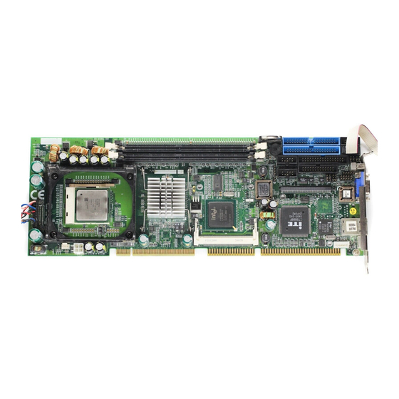
Page 27: Figure 2-1: Nupro-842 Top View
NuPRO-842 Figure 2-1: NuPRO-842 Top View CPU P4/P4-M GMCH 82845GV ICH4 FW82801DB Clock Generator PCI to ISA Bridge IT8888 Intel GB Ethernet 82540EM Intel GB Ethernet 82540EM Firmware Hub 842PLD RS422/RS485 PLD CN23 ATX Power CONNECTOR CPU HEATSINK SKT Jumpers and Connectors... -
Page 28: Table 2-1: Nupro-842 Connectors
CPU FAN CN21 CPU POWER CONNECTOR DIMM1 DDR DIMM SOCKET DIMM2 DDR DIMM SOCKET GMCH HEATSINK CN19 MINI PCI CONNECTOR FSB FREQUENCY SELECTION JUMPER EXTERNAL USB PIN HEADER CLEAR CMOS JUMPER CR2032 BATTERY HOLDER BUZZER CN15 DB-842DVI CNN CN16 USB2.0 PIN HEADER CN18 USB2.0 PIN HEADER PRINTER PORT... -
Page 29: Vga Connector
NuPRO-842 VGA Connector Signal Function Analog RED Green Analog GREEN Blue Analog BLUE No Connect Ground Ground Ground Ground Ground Ground No connect DDCDAT DDC Data for CRT HSYNC Horizontal sync for Monitor VSYNC Vertical sync for Monitor DDCCLK DDC CLK for CRT Table 2-2: VGA Connector COM1/COM2 Pin Header Signal... -
Page 30: Lan Rj-45 Connector
LAN RJ-45 Connector Signal Function green LAN2_TDP1 Transmit Data1 + LAN2_TDN1 Transmit Data1 - LAN2_RDP2 Receive Data2 + LAN2_RDP3 Receive Data3 + LAN2_RDN3 Receive Data3 - LAN2_RDN2 Receive Data2 - LAN2_TDP4 Transmit Data4 + yellow LAN2_TDN4 Transmit Data4 - Table 2-4: LAN RJ-45 Connector Parallel Port Connector Signal Name Pin Pin Signal Name... -
Page 31: Case Open Connector
NuPRO-842 Case Open connector Signal is connected to a limit switch sensor of the chassis to detect if the case is opened or closed. SIGNAL FUNCTION CASEOPEN# Case Open Signal Ground Table 2-6: Case Open Connector Pin Definition CPU Fan1/Fan2 connector Pin # Signal Name Fan power Fan speed... -
Page 32: Floppy Disk Connector
Floppy Disk Connector Pin Function Pin Function Ground Extended Density Ground No Connect Data Rate Ground Index Ground Motor A Select Ground Drive B Select Ground Drive A Select Ground Motor B Select Ground Step Direction Ground Step Pulse Ground Write Data Ground Write Gate... -
Page 33: Primary/Secondary Ide Connector
NuPRO-842 Primary/Secondary IDE Connector Signal Pin Pin Signal BRSTDRVJ DDP7 DDP8 DDP6 DDP9 DDP5 DDP10 DDP4 10 DDP11 DDP3 12 DDP12 DDP2 14 DDP13 DDP1 16 DDP14 DDP0 18 DDP15 PDDREQ PDIOWJ PDIORJ PIORDY 28 PCSEL PDDACKJ IRQ14 DAP1 DIAG DAP0 DAP2 CS1P... -
Page 34: Front Panel Pin Header
Front Panel Pin Header SIGNAL FUNCTION PIN GROUP Power WDTLED# Watch Dog LED Signal Power LED PLED Power LED Signal KEYLOCK Keyboard lock Key Lock Ground Ground No connect PWRON Power-on signal ATX Power Connector +5VSB Standby Power PME# Power Management Event WDSPK Speaker signal No connect... -
Page 35: Mini Pci Socket
NuPRO-842 Mini PCI Socket SIGNAL SIGNAL SIGNAL SIGNAL +3.3V FRAME# CLKRUN# TRDY# SERR# STOP# +3.3V PERR# DEVSEL# C/BE[1] AD[14] AD[15] 16 EX_INTC# AD[13] INTB# AD[12] AD[11] +3.3V INTA# AD[10] EX_CLK 22 EX_INTD# AD[9] +3.3VS AD[8] C/BE[0] RESET# AD[7] +3.3V +3.3V +3.3V AD[6] REQ#... -
Page 36: Usb Connector
SIGNAL SIGNAL SIGNAL SIGNAL AD[23] IDSEL# AC_ID1# AC_RST# AD[21] AD[22] AD[19] AD[20] AD[17] AD[18] C/BE[2] AD[16] 122 MPCIACT# IRDY# +5Analog +3.3VS Table 2-12: Mini PCI Socket Pin Definition USB Connector Pin Signal Name USB- USB+ Table 2-13: USB Connectors Pin Definition AC’97 Connector SIGNAL FUNCTION... -
Page 37: Usb Pin Header
NuPRO-842 USB Pin Header PIN SIGNAL FUNCTION PIN SIGNAL FUNCTION Power Power USB - Data (-) USB - Data (-) USB + Data (+) USB + Data (+) Ground Ground Empty Empty Table 2-15: USB Pin Header Thermal Connector PIN SIGNAL FUNCTION TGND Thermal Ground... -
Page 38: Clear Cmos
selected through the BIOS menu. However, some options still need to be configured by jumpers. Description Location Clear CMOS FSB Frequency Selection COM2 Function Selection JP1-3 COM2 RS-485+ Function Selection Table 2-18: Jumpers Definitions Clear CMOS RTC status JP6 NuPRO-842 JP6 Normal Clear CMOS 2-3 Table 2-19: Clear CMOS RTC RAM... -
Page 39: Fsb Frequency
NuPRO-842 FSB Frequency FSB Frequency JP8 NuPRO-842 JP8 Auto 400 MHZ 533 MHZ Table 2-20: FSB Frequency The NuPRO-842 will automatically detect Front Side Bus speed, or you can manually force it with jumper JP8. Jumpers and Connectors... -
Page 40: Com2 Function Selection
COM2 Function Selection FUNCTION JP1 JP2 JP3 Jumper Setting RS-232 1-2 4-5 RS-422 2-3 5-6 RS-485 2-3 5-6 Table 2-21: COM2 Function Selection COM2 is configurable to act in accordance with the following stan- dards: RS-232, RS-422, and RS-485. Use jumpers J1, J2, and J3 to adjust as needed. -
Page 41: Com2 Mode Selection
NuPRO-842 COM2 Mode Selection Mode Jumper Setting RS-422 / RS-485 1-2 4-5 RS-485+ 2-3 5-6 Table 2-22: COM2 Mode Selection The mode of COM2 can be changed using jumper JP4. Jumpers and Connectors... - Page 42 This page intentionally left blank. Jumpers and Connectors...
-
Page 43: Getting Started
NuPRO-842 Getting Started This chapter gives a summary of what is required to setup an operational system using the NuPRO-842. Hardware installation and BIOS overview is discussed. 3.1 CPU Installation The NuPRO-842 CPU module supports a single Intel mPGA478 Pentium 4 processor or 478-pin Micro Flip-Chip Pin Grid Array (Micro-FCPGA) Pentium 4 Processor-M. -
Page 44: Memory Configuration Options
Memory Configuration Options The NuPRO-842 has flexible memory configuration options, including support for 64MB, 128MB, 256MB, 512MB, and 1GB modules. Note that the modules must all be the same type and density and must be installed in pairs. If only one pair of DIMM modules is used, populate DM1 and DM2 first. -
Page 45: Connecting Ide Devices To The Nupro-842
NuPRO-842 1. Align the module to the socket so that the edge connec- tors on the module match the socket sections. 2. Hold the module perpendicular to the motherboard and press the edge connector into the socket. 3. Press the module fully into the socket so that the socket retaining arms swing up and engage the retention notches at each end of the module. -
Page 46: Operating System Installation
Setup parameters are divided into different categories. The avail- able categories are listed in menus. The parameters within the highlighted (current) category are listed in the bottom portion of the Setup screen. Context sensitive help is displayed in the right portion of the screen for each parameter. -
Page 47: Device Driver Installation
NuPRO-842 Device Driver Installation To install drivers for the NuPRO-842, refer to the installation infor- mation in this chapter. Basic driver installation information for Win- dows 98/ME/NT4.0/2000/XP are outlined in this section. The drivers are located in the following directories of the CD-ROM: Chipset driver \CHIPDRV\Chipset\I845GV LAN relative driver... -
Page 48: Driver Installation
1. Check System Requirements. Windows 98/ME/2000/XP must be fully installed and running on the system prior to running this software. 2. Close any running applications. 3. The files are stored in an integrated application setup program. This program is designed for a Windows 98/ME/2000/XP program that allows the INF files to be installed. - Page 49 NuPRO-842 Installing the Drivers for Windows 98/ME 1. Boot Windows 98/ME. 2. The driver is included in the ADLINK CD. Run win9x131.exe under directory: X:\CHIP- DRV\VGA\I845GV. 3. Click Next> on Welcome screen. And select Typical on Setup Type screen and click Next>. 4.
-
Page 50: Lan Driver Installation
Installing the Drivers for Windows 2000/XP 1. Boot Windows 2000/XP. 2. The driver is included in the ADLINK CD. Run the win2k_xp131.exe under directory: X:\CHIP- DRV\VGA\I845GV. 3. Click Next> on Welcome screen. And select Typical on Setup Type screen and click Next>. 4. - Page 51 NuPRO-842 1. Boot Windows 2000. 2. The driver is included in the ADLINK CD. Run Setup.exe under directory: X:\CHIP- DRV\LAN\82540EM\pro2kxpm. 3. Click the Install now button on the Installation instruc- tions screen to install the drivers. 4. Click Finish button to finish the installation. Driver Installation on Windows 98/98SE/ME Windows 98 will install the LAN drivers automatically.
- Page 52 This page intentionally left blank. Device Driver Installation...
-
Page 53: Watchdog Timer
NuPRO-842 Watchdog Timer This chapter explains the operation of the NuPRO-842 watchdog timer. It provides an overview of watchdog operations and features. Sample programs are located at X:\CHIPDRV\WDT\DOS\NP842. 5.1 Watchdog Timer Overview The primary function of the watchdog timer is to monitor the NuPRO-842 operation and to reset the system if the software fails to function as programmed. - Page 54 Watchdog Reset An application using the reset feature enables the watchdog reset, sets the terminal count period, and periodically strobes the watchdog to keep it from resetting the system. If a strobe is missed, the watchdog times out and resets the system hard- ware.
-
Page 55: Db-842Dvi Display Interface
NuPRO-842 DB-842DVI Display Interface The DB-842DVI is a multi-display output daughter board add-on for the NuPRO-842. It supports DVI, LVDS, and TTL displays with resolutions of 800x600, and 1024x768 at 60Hz. Figure 6-1: DB-842DVI Functional Block Diagram DB-842DVI Display Interface... -
Page 56: Db-842Dvi Jumpers And Pinouts
6.1 DB-842DVI Jumpers and Pinouts FUNCTION +5V FPVDD Table 6-1: Flat Panel Voltage Selection (JP1) +3.3V FPVDD 2-3 FUNCTION Enable LVDS 1-2 Disable LVDS 2-3 Table 6-2: LVDS Panel Enable (JP2) DB-842DVI Display Interface... -
Page 57: Table 6-3: Dvi Panel Connector (Cn1)
NuPRO-842 SIGNAL FUNCTION SIGNAL FUNCTION DVITDC2- TMDS Data 2- DVITDC2+ TMDS Data 2+ Ground No Connect No Connect DDCCLK I2C Clock DDCDATA I2C Data No Connect DVITDC1- TMDS Data 1- 10 DVITDC1+ TMDS Data 1+ Ground No Connect No Connect Power +5V Ground HPDET... -
Page 58: Table 6-5: Ttl Panel Connector
PIN SIGNAL FUNCTION SIGNAL FUNCTION No Connect No Connect Ground Ground FPVDD +5V/3.3V FPVDD +5V/3.3V No Connect Ground Blue Data 0 Blue Data 1 Blue Data 2 Blue Data 3 Blue Data 4 Blue Data 5 Blue Data 6 Blue Data 7 Green Data 0 18 Green Data 1 Green Data 2 20... -
Page 59: Important Safety Instructions
NuPRO-842 Important Safety Instructions For user safety, please read and follow all instructions, WARNINGS, CAUTIONS, and NOTES marked in this manual and on the associated equipment before handling/operating the equipment. Read these safety instructions carefully. Keep this user’s manual for future reference. Read the specifications section of this manual for detailed information on the operating environment of this equipment. - Page 60 Never attempt to fix the equipment. Equipment should only be serviced by qualified personnel. A Lithium-type battery may be provided for uninterrupted, backup or emergency power. Risk of explosion if battery is replaced with one of an incorrect type. Dispose of used batteries appropriately. WARNING: Equipment must be serviced by authorized technicians when:...
-
Page 61: Getting Service
Address: 5215 Hellyer Avenue, #110, San Jose, CA 95138, USA Tel: +1-408-360-0200 Toll Free: +1-800-966-5200 (USA only) Fax: +1-408-360-0222 Email: info@adlinktech.com ADLINK Technology (China) Co., Ltd. Address: (201203) 300 Fang Chun Rd., Zhangjiang Hi-Tech Park, Pudong New Area, Shanghai, 201203 China Tel: +86-21-5132-8988 Fax:... - Page 62 Address: 84 Genting Lane #07-02A, Cityneon Design Centre, Singapore 349584 Tel: +65-6844-2261 Fax: +65-6844-2263 Email: singapore@adlinktech.com ADLINK Technology Singapore Pte. Ltd. (Indian Liaison Office) Address: No. 1357, "Anupama", Sri Aurobindo Marg, 9th Cross, JP Nagar Phase I, Bangalore - 560078, India Tel: +91-80-65605817 Fax: +91-80-22443548 Email: india@adlinktech.com...
Need help?
Do you have a question about the NuPRO-842DV/P and is the answer not in the manual?
Questions and answers