Sign In
Upload
Manuals
Brands
ADLINK Technology Manuals
Motherboard
CoreModule 720
ADLINK Technology CoreModule 720 Manuals
Manuals and User Guides for ADLINK Technology CoreModule 720. We have
1
ADLINK Technology CoreModule 720 manual available for free PDF download: Reference Manual
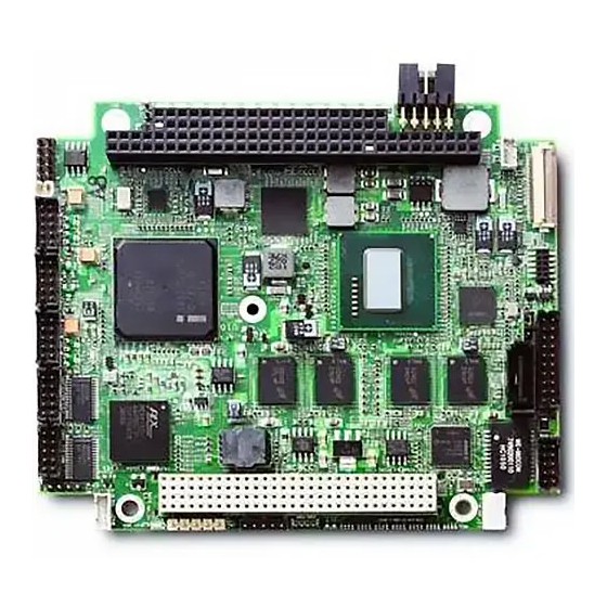
ADLINK Technology CoreModule 720 Reference Manual (56 pages)
Brand:
ADLINK Technology
| Category:
Motherboard
| Size: 1.64 MB
Table of Contents
Table of Contents
3
Chapter 1 About this Manual
7
Purpose of this Manual
7
References
7
Chapter 2 Product Overview
9
PC/104 Architecture
9
Product Description
10
Figure 2-1. Stacking PC/104-Plus Modules with the Coremodule 720
10
Module Features
11
Block Diagram
13
Figure 2-2. Functional Block Diagram
13
Major Component (Ics) Definitions
14
Table 2-1. Major Component Descriptions and Functions
14
Figure 2-3. Component Locations (Top Side)
16
Figure 2-4. Component Locations (Bottom Side)
16
Header, Connector, and Socket Definitions
17
Table 2-2. Module Header and Connector Descriptions
17
Figure 2-5. Connector Pin Sequences
18
Figure 2-6. Header, Connector, and Socket Locations (Top Side)
18
Jumper Header Definitions
19
Figure 2-7. Jumper Header Locations (Top Side)
19
Table 2-3. Jumper Settings
19
Specifications
20
Physical Specifications
20
Table 2-4. Weight and Footprint Dimensions
20
Mechanical Specifications
21
Figure 2-8. Mechanical Overview (Top Side)
21
Power Specifications
22
Environmental Specifications
22
Table 2-5. Power Supply Requirements
22
Table 2-6. Environmental Requirements
22
Thermal/Cooling Requirements
23
Figure 2-9. Stack Height of Cooling Assembly
23
Chapter 3 Hardware
25
Overview
25
Cpu
26
Graphics
26
Memory
26
Interrupt Channel Assignments
27
Memory Map
27
Table 3-1. Interrupt Channel Assignments
27
Table 3-2. Memory Map
27
I/O Address Map
28
Table 3-3. I/O Address Map
28
Reference Manual Coremodule 720
28
Serial Interfaces
29
Table 3-4. Serial 1 (COM0) Interface Pin Signal Descriptions (J10)
29
USB Interfaces
30
Table 3-5. Serial 2 (COM1, 2, and 3) Interface Pin Signal Descriptions (J11)
30
Table 3-6. USB0 and USB1 Interface Pin Signals (J12)
30
Table 3-7. USB2 and USB3 Interface Pin Signals (J14)
31
Table 3-8. USB4 and USB5 Interface Pin Signals (J13)
31
Ethernet Interface
32
Table 3-9. Ethernet Interface Pin Signal Descriptions (J8)
32
Video (SDVO/LVDS) Interfaces
33
Table 3-10. SDVO Interface Pin Signals (J15)
33
Table 3-11. LVDS Video Interface Pin Signals (J23)
34
Power Interface
35
User GPIO Interface
35
Table 3-12. Power Interface Pin Signals (J19)
35
Table 3-13. User GPIO Interface Pin Signals (J3)
35
Utility Interface
36
Power Button
36
Reset Switch
36
Speaker
36
Table 3-14. Utility Interface Pin Signals (J22)
36
System Management Bus (Smbus)
37
CAN Bus Interface
37
Table 3-15. Smbus Reserved Addresses
37
Table 3-16. Smbus Pin Signals (J24)
37
Table 3-17. CAN Interface Pin Signals (J4)
37
I2C Interface
38
System Fan
38
Battery
38
Table 3-19. System Fan Pin Signals (J21)
38
Table 3-20. External Battery Input Header (J20)
38
Ethernet External LED
39
Miscellaneous
39
SSD (Solid State Drive)
39
Real Time Clock (RTC)
39
Oops! Jumper (BIOS Recovery)
39
Figure 3-1. Oops! Jumper Serial Port (DB9)
39
Table 3-21. Ethernet External LED Pin Signals (J9)
39
Serial Console
40
Serial Console Setup
40
Hot (Serial) Cable
40
Watchdog Timer
40
Figure 3-2. Serial Console Jumper
40
Chapter 4 BIOS Setup
41
Introduction
41
Entering BIOS Setup (Local Video Display)
41
Entering BIOS Setup (Serial Port Console)
41
OEM Logo Utility
42
Logo Image Requirements
42
BIOS Setup Menus
43
Main BIOS Setup Screen
43
Figure 4-1. Main BIOS Setup Screen
43
Advanced BIOS Setup Screen
44
Figure 4-2. Advanced BIOS Setup Screen
44
Chipset BIOS Setup Screen
47
Figure 4-3. Chipset BIOS Setup Screen
47
Boot BIOS Setup Screen
49
Figure 4-4. Boot BIOS Setup Screen
49
Security BIOS Setup Screen
50
Figure 4-5. Security BIOS Setup Screen
50
Save & Exit BIOS Setup Screen
51
Figure 4-6. Save & Exit BIOS Setup Screen
51
Appendix A Technical Support
53
Table A-1. Technical Support Contact Information
53
Index
55
Advertisement
Advertisement
Related Products
ADLINK Technology LittleBoard 735
ADLINK Technology CoreModule 730
ADLINK Technology CoreModule 745
ADLINK Technology CoreModule 740
ADLINK Technology CoreModule 920
ADLINK Technology CoreModule 430
ADLINK Technology 72XX Series
ADLINK Technology ReadyBoard 740
ADLINK Technology COM Express Type 7 Starter Kit Plus
ADLINK Technology COM Express 7
ADLINK Technology Categories
Computer Hardware
Motherboard
PCI Card
Control Unit
Controller
More ADLINK Technology Manuals
Login
Sign In
OR
Sign in with Facebook
Sign in with Google
Upload manual
Upload from disk
Upload from URL