
Subscribe to Our Youtube Channel
Related Manuals for ADLINK Technology NuPRO-A40H


Summary of Contents for ADLINK Technology NuPRO-A40H
- Page 1 NuPRO-A40H Full-Size PICMG 1.0 Intel® Core™ i7/i5/i3 LGA1155 SHB User’s Manual 2.00 Manual Rev.: September 11, 2013 Revision Date: 50-13072-1010 Part No: Advance Technologies; Automate the World.
-
Page 2: Revision History
Revision History Revision Release Date Description of Change(s) 1.00 2013/07/19 Preliminary release Initial release (add BIOS, WDT, system 2.00 2013/09/11 resources) Revision History... -
Page 3: Preface
NuPRO-A40H Preface Copyright 2013 ADLINK Technology, Inc. This document contains proprietary information protected by copy- right. All rights are reserved. No part of this manual may be repro- duced by any mechanical, electronic, or other means in any form without prior written permission of the manufacturer. - Page 4 Chapter 2, Hardware Information: Provides technical informa- tion on connectors and jumpers for configuring the NuPRO-A40H. Chapter 3, Getting Started: Illustrates how to install components on the NuPRO-A40H such as CPU, heatsink, and memory mod- ules. Chapter 4, Driver Installation: Provides information on how to install the NuPRO-A40H device drivers.
- Page 5 NuPRO-A40H Conventions Take note of the following conventions used throughout this manual to make sure that users perform certain tasks and instructions properly. Additional information, aids, and tips that help users perform tasks. NOTE: NOTE: Information to prevent minor physical injury, component dam- age, data loss, and/or program corruption when trying to com- plete a task.
- Page 6 This page intentionally left blank. Preface...
-
Page 7: Table Of Contents
NuPRO-A40H Table of Contents Revision History..............ii Preface ..................iii List of Figures ................ xi List of Tables................ xiii 1 Introduction ................ 1 Overview................1 Features................2 Specifications............... 3 Block Diagram ..............5 Functional Description ............6 Mechanical Drawing ............8 I/O Connectivity .............. - Page 8 4 Driver Installation.............. 35 Chipset Driver ..............35 Display Driver..............35 Ethernet Driver..............36 Audio Driver ............... 36 5 BIOS Setup ................ 37 Starting the BIOS ............... 37 Main Setup................. 41 Advanced BIOS Setup ............43 5.3.1 ACPI Settings ..............44 5.3.2 CPU Configuration............
- Page 9 NuPRO-A40H Important Safety Instructions ..........83 Getting Service..............85 Table of Contents...
- Page 10 This page intentionally left blank. Table of Contents...
-
Page 11: List Of Figures
NuPRO-A40H List of Figures Figure 1-1: NuPRO-A40H Block Diagram.......... 5 Figure 1-2: NuPRO-A40H Board Dimensions........8 Figure 2-1: Rear Panel I/O Ports............13 Figure 2-2: Connectors and Jumpers..........15 List of Figures... - Page 12 This page intentionally left blank. List of Figures...
-
Page 13: List Of Tables
NuPRO-A40H List of Tables Table 1-1: NuPRO-A40H I/O Connectivity........9 Table 1-2: Core™ i7-3770 Processor Power Consumption.... 10 Table B-1: System Memory Map............. 75 Table B-2: Direct Memory Access Channels........75 Table B-3: IO Map ................77 Table B-4: IRQ Lines PIC Mode............78 Table B-5: IRQ Lines APIC Mode ........... - Page 14 This page intentionally left blank. List of Tables...
-
Page 15: Introduction
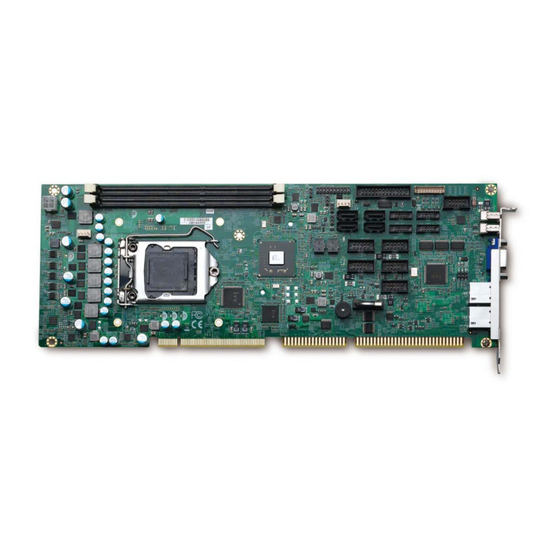
NuPRO-A40H Introduction 1.1 Overview The ADLINK NuPRO-A40H is a PICMG 1.0 Single Board Computer (SBC) supporting generation Intel® Core™ i7/i5/i3 and Pentium® processors in LGA1155 package to deliver a scalable high performance platform for a wide array of industrial applications. The NuPRO-A40H supports 22nm process CPUs at up to 3.4 GHz with integrated graphics and memory... -
Page 16: Features
1.2 Features Supports 3rd Generation Intel® Core™ i7/i5/i3, and Pen- tium® processors in LGA1155 package Integrated Intel® HD Graphics with VGA and DVI-D output Dual Gigabit Ethernet 8x USB 2.0 ports (2x faceplate, 6x onboard pin headers) 4x SATA 3 Gb/s ports 6x COM ports (including 1x RS-232/422/485 with auto flow control) Watchdog Timer, Hardware Monitor... -
Page 17: Specifications
NuPRO-A40H 1.3 Specifications System 3rd Gen Intel® Core™ processors in LGA1155 package: • Intel® Core™ i7-3770, 3.4 GHz, 8M Cache, 22nm, 95W • Intel® Core™ i5-3550, 3.0 GHz, 6M Cache, 22nm, 95W • Intel® Core™ i3-3220, 3.3 GHz, 3M Cache, 22nm, 65W •... - Page 18 Ethernet • Dual Intel® I211-AT Gigabit Ethernet Controller • Supports Preboot Execution Environment (PXE), Controller Wake-On-LAN, 9KB Jumbo Frames • Two RJ-45 Ethernet ports Ports Mechanical and Environment • Standard full-size PICMG 1.0 SBC Form Factor • 338 x 122 mm (L x W) Dimensions •...
-
Page 19: Block Diagram
(4x Master) DVI-D Intel Intel PCI to ISA Bus 8 USB 2.0 Ports Bridge Intel I211-AT Dual Intel I211-AT 4 SATA Ports at 3.0Gb/s 6 COM Audio LEMT BIOS Super Pin Header for KB/MS Figure 1-1: NuPRO-A40H Block Diagram Introduction... -
Page 20: Functional Description
1.5 Functional Description Processor Support The NuPRO-A40H is PICMG 1.0 Single Board Computer support- ing the 3rd Generation Intel® Core™ processor family (Intel® Core™ i7/i5/i3, Pentium®) in LGA1155 socket. An integrated memory controller supports dual channel 1333/1600 MHz DDR3 and Intel® HD Graphics is integrated onboard the CPU. Direct Media Interface (DMI) and Flexible Display Interface (FDI) provide connectivity to the Intel®... - Page 21 NuPRO-A40H Serial ATA The NuPRO-A40H provides four Serial ATA ports with data trans- fer rates of up to 3.0 GB/s. Universal Serial Bus (USB 2.0) The NuPRO-A40H provides 8 USB 2.0 ports supporting transfer rates up to 480 Mb/s (2x faceplate, 6x onboard pin headers).
-
Page 22: Mechanical Drawing
1.6 Mechanical Drawing Figure 1-2: NuPRO-A40H Board Dimensions Introduction... -
Page 23: I/O Connectivity
COM1-2 — — 2.00mm pitch COM3-6 — — Parallel port cable w/ bracket — — optional (P/N 30-25019-1000) SATA — — — PCI 32bit/33MHz — — Via ITE IT8892E — — Via ITE IT8888G Table 1-1: NuPRO-A40H I/O Connectivity Introduction... -
Page 24: Power Consumption
1.8 Power Consumption Intel® Core™ i7-3770 8M Cache 3.40GHz) Test Configuration Intel® Core™ i7-3770 8M Cache 3.40GHz Transcend 8GB DDR3 1600 DIMMx2 Memory Windows® 7 (Idle) +12V Total Power Req. 1.47A 2.77A — Current (A) 17.64W 13.85W 31.49W Power (W) Windows®... -
Page 25: Package Contents
User’s manual Package contents may vary with ordering options. NOTE: NOTE: The NuPRO-A40H must be protected from static discharge and physical shock. Never remove any of the socketed parts except at a static-free workstation. Use the anti-static bag shipped with WARNING: the product to handle the board. - Page 26 This page intentionally left blank. Introduction...
-
Page 27: Hardware Information
NuPRO-A40H Hardware Information This chapter provides information on the NuPRO-A40H board lay- out, connector pin assignments, and jumper settings. 2.1 Rear Panel I/O Ports Figure 2-1: Rear Panel I/O Ports Connector Description LAN1 port Gigabit Ethernet (RJ-45) LAN2 port Gigabit Ethernet (RJ-45) - Page 28 LAN (RJ-45) Ports 10BASE-T/ Pin # 1000BASE-T 100BASE-TX BI_DA+ BI_DA- LED1 LED2 BI_DB+ BI_DC+ BI_DC- BI_DB- BI_DD+ BI_DD- Refer to the table below for the LAN port LED definitions. LED1 LED2 Status Description Status Description No Link 10 Mb connection Linked Green 100 Mb connection...
-
Page 29: Board Layout
NuPRO-A40H 2.2 Board Layout 7 8 9 10 11 Figure 2-2: Connectors and Jumpers Connector Description CN24 ATX 12V Power connector DIMM1/2 DDR3 DIMM slots CN23 System Panel pin header FAN2 FAN2 connector CN14 Watchdog disable jumper CN30 Parallel Port connector... -
Page 30: Onboard Connectors
2.3 Onboard Connectors ATX 12V Power Connector (CN24) Pin # Signal +12V DC +12V DC The ATX 12V power connector must be connected to provide sufficient power to the SBC in either ATX or AT modes. See “Installing the Power Connectors” on page 36. NOTE: NOTE: Fan Connectors (FAN1/2) - Page 31 NuPRO-A40H System Panel Pin Header (CN23) (2x10 pin header, 2.54mm pitch) Connects to chassis-mounted buttons, speakers, and LEDs. Pin # Signal Function Pin Group +5V Power Power LED HC_PLED-L Power LED signal Ground Ground ATX Power ATX_PSON-L ATX Power-On signal...
- Page 32 Parallel Port Onboard Connector (CN30) (2x13 box header, 2.54mm pitch) Pin # Signal Pin # Signal Line Printer Strobe Auto-Feed Parallel Data 0 Error Parallel Data 1 Initialize Parallel Data 2 Select Parallel Data 3 Ground Parallel Data 4 Ground Parallel Data 5 Ground Parallel Data 6...
- Page 33 NuPRO-A40H DVI-D Onboard Connector(CN17) (2x10 Wafer connector, 2.00mm pitch) Pin # Signal Pin # Signal DVI-Clock+ DVI-Data0- DVI-Clock- DVI-Data0+ DVI-I2C-Clock DVI-Data1- DVI-I2C-Data DVI-Data1+ DVI-HPD DVI-Data2- DVI-Data2+ DVI-D Bracket Connector (optional cable w/ bracket, P/N 30-01052-2000) Pin # Signal Pin #...
- Page 34 COM1 Connector (RS-232/422/485/485+) (CN10) (2x5 box header, 2.54mm pitch) Pin # RS-232 RS-422/485+ RS-485 TXD- Data- TXD+ Data+ RXD+ RXD- Note: See BIOS: Advanced > Super I/O to set COM1 to RS-232/ 422/485 mode. COM2/3/4/5/6 Connectors (RS-232) (CN12/18/19/25/26) (2x5 box header, 2.00mm pitch) Pin # RS-232 Signal Hardware Information...
- Page 35 NuPRO-A40H COM Bracket Connectors (cables w/ bracket supplied with the NuPRO-A40H - DB9 connector) Pin # RS-232 RS422/485+ RS485 TXD- Data- TXD+ Data+ RXD+ USB 2.0 Connectors (CN3/6/8) (2x5 box header, 2.54mm pitch) Pin # Signal Pin # Signal USB0-...
- Page 36 PS/2 Keyboard/Mouse Pin Header (CN16) (2x3 pin header, 2.54mm pitch) Pin # Signal Pin # Signal KBDATA KBCLK MSDATA MSCLK KM_VCC PS/2 Keyboard/Mouse Bracket Connectors (optional cable w/ bracket, P/N: 30-01019-2000) PS/2 Mouse Port (green) Pin # Signal Function MSDATA Mouse Data not connected Ground...
- Page 37 NuPRO-A40H HD Audio Daughter Board Connector (CN9) (2x5 box header, 2.54mm pitch) This connector is designed for use with the ADLINK DB-Audio2 daughter board. Pin # Signal Function Ground AUD_BCLK Audio Clock Ground ICH_AUD_SDIN1 Audio Data Input + 5V ICH_AUD_SDOUT Audio Data Output...
-
Page 38: Jumpers
2.4 Jumpers Watchdog Disable Jumper (CN14) WDT Status Connection Normal (default) 1 – 2 Disabled 2 – 3 Clear CMOS Jumper (CN28) To clear the BIOS settings (RTCRTS# asserts): 1. Power down and disconnect power from the system. 2. Short pins 2-3 on JP1. 3. - Page 39 NuPRO-A40H Clear RTC Jumper (CN29) To clear the BIOS settings and data/time (SRTCRST# and RTCRST# assert): 1. Power down and disconnect power from the system. 2. Short pins 2-3 on JP1. 3. Reconnect power and power up the system. After power up, remove the jumper cap from pins 2-3 and reinstall it to pins 1-2.
- Page 40 This page intentionally left blank. Hardware Information...
-
Page 41: Getting Started
This chapter provides information on how to install components on the NuPRO-A40H SHB. 3.1 Installing the CPU The NuPRO-A40H supports an Intel® Core™ i7/i5/i3 or Pentium® processor in an LGA1155 socket. Disconnect all power to the board before installing a CPU to prevent damaging the board and CPU. - Page 42 2. Raise the locking arm to unlock the load plate. 3. Lift the load plate to uncover the socket. 4. Remove the plastic protective cover from the socket. Note the locations of the alignment keys (A) and Pin 1 indicator (B). Do NOT touch socket contacts.
- Page 43 NuPRO-A40H 5. Hold the CPU using thumb and forefinger as shown. Position the CPU over the socket, matching the notches on the sides of the CPU with the alignment keys on the socket (A). The golden triangle on the CPU must be positioned at the corner of the socket with the Pin 1 indi- cator as shown (B).
- Page 44 7. Gently lower the load plate. Make sure the front edge of the plate is under the screw as indicated. 8. Lower the locking arm and fasten it to the retention tab (A). The load plate should be locked underneath the screw as shown (B).
-
Page 45: Installing The Cpu Fan And Heatsink
NuPRO-A40H 3.2 Installing the CPU Fan and Heatsink The CPU requires a chassis with an airflow inlet and maximum internal ambient temperature of 50° C. A especially-designed CPU fan and heatsink must be installed before using the SHB. CAUTION: Failure to install a CPU fan and heatsink may damage the sys- tem host board and/or the CPU. -
Page 46: Installing Memory Modules
3.3 Installing Memory Modules The NuPRO-A40H supports up to 16 GB of DDR3 1333/1600 MHz memory modules in two DIMM sockets. A DDR3 module has a 240-pin footprint compared to the legacy 184-pin DDR DIMM. DDR3 modules are notched to facilitate correct installation in the DIMM sockets. - Page 47 NuPRO-A40H 3. Align the memory module on the socket making sure that the notch matches the break on the socket. Notch Break 4. Insert the module firmly into the slot until the retaining clips snap back inwards and the module is securely seated.
-
Page 48: Installing The Power Connectors
ATX 12V Power Connector The NuPRO-A40H requires +12V DC power connected to CN24 for proper operation in either ATX or AT modes. If necessary, order an ATX12V Convert Cable from ADLINK for use with Molex 4-pin power connectors (P/N 30-00006-0000). -
Page 49: Driver Installation
NuPRO-A40H Driver Installation This chapter provides information on how to install the NuPRO-A40H device drivers under Windows XP. The device drivers are located in the following ADLINK All-in-One DVD directories: \NuPRO\NuPRO-A40H\Chipset\ Chipset \NuPRO\NuPRO-A40H\VGA\ Display \NuPRO\NuPRO-A40H\Ethernet\ Ethernet .Net Framework \NuPRO\NuPRO-A40H\Others\ \Audio Daughter Board\DB-Audio2\ Audio Install the Windows operating system before installing any driver. -
Page 50: Ethernet Driver
2. Run the program Microsoft_Net_Framework_v3.5_SP1.exe and follow the onscreen instructions.Restart the system if prompted. 3. Locate the directory X:\NuPRO\NuPRO-A40H\VGA\ on the ADLINK All-in-One DVD, and extract the file setup.exe from the following archive: VGA_winxp.zip. 4. Run the program setup.exe and follow the onscreen instructions. -
Page 51: Bios Setup
NuPRO-A40H BIOS Setup The following chapter describes basic navigation for the AMIBIOS® EFI BIOS setup utility. 5.1 Starting the BIOS To enter the setup screen, follow these steps: 1. Power on the motherboard 2. Press the < Delete > key on your keyboard when you see the following text prompt: <... - Page 52 Setup Menu The main BIOS setup menu is the first screen that you can navi- gate. Each main BIOS setup menu option is described in this user’s guide. The Main BIOS setup menu screen has two main frames. The left frame displays all the options that can be configured.
- Page 53 NuPRO-A40H There is a hot key legend located in the right frame on most Note: setup screens. The < F8 > key on your keyboard is the Fail-Safe key. It is not dis- played on the key legend by default. To set the Fail-Safe settings of the BIOS, press the <...
- Page 54 The < F10 > key allows you to save any changes you have made and exit Setup. Press the < F10 > key to save your changes. The following screen will appear: Press the < Enter > key to save the configuration and exit. You can also use the <...
-
Page 55: Main Setup
NuPRO-A40H 5.2 Main Setup When you first enter the Setup Utility, you will enter the Main setup screen. You can always return to the Main setup screen by select- ing the Main tab. There are two Main Setup options. They are described in this section. - Page 56 System Time/System Date Use this option to change the system time and date. Highlight Sys- tem Time or System Date using the < Arrow > keys. Enter new val- ues using the keyboard. Press the < Tab > key or the < Arrow > keys to move between fields.
-
Page 57: Advanced Bios Setup
NuPRO-A40H 5.3 Advanced BIOS Setup Select the Advanced tab from the setup screen to enter the Advanced BIOS Setup screen. You can select any of the items in the left frame of the screen, such as SuperIO Configuration, to go to the sub menu for that item. -
Page 58: Acpi Settings
5.3.1 ACPI Settings Enable APIC Auto Configuration BIOS ACPI Auto Configuration. Options: Enabled/Disabled. ACPI Sleep State Select the highest ACPI sleep state the system will enter, when the SUSPEND button is pressed. Options: S1, S3, Suspend Disable. AC Power Shutdown ATX mode: OS will turn off system power when shutdown. -
Page 59: Cpu Configuration
NuPRO-A40H 5.3.2 CPU Configuration Active Processor Cores Number of cores to enable in processor. Options: All, 1, 2. Limit CPUID Value Maximum When Enabled, the processor will limit the maximum CPUID input value to 03h when queried, even if the processor sup- ports a higher CPUID input value. - Page 60 Intel® Virtualization Tech When enabled, Intel® Virtualization Technology (Intel® VT) makes a single system appear as multiple independent sys- tems to software. This allows for multiple, independent operat- ing systems to be running simultaneously on a single system. BIOS Setup...
-
Page 61: Sata Configuration
NuPRO-A40H 5.3.3 SATA Configuration SATA Mode Options: IDE, RAID, AHCI. IDE Legacy/Native Mode Selection IDE Legacy/Native Mode Selection. SATA Port 0,1,4,5 Display SATA device name string. BIOS Setup... -
Page 62: Usb Configuration
5.3.4 USB Configuration Legacy USB Support Legacy USB Support refers to USB mouse and keyboard sup- port. Normally if this option is not enabled, any attached USB mouse or USB keyboard will not become available until a USB compatible operating system is fully booted with all USB driv- ers loaded. - Page 63 NuPRO-A40H USB transfer time-out The time-out value for Control, bulk, and Interrupt transfers. Device reset time-out USB mass storage device start Unit command time-out. Device power-up delay Maximum time the device will take before it properly reports itself to the Host Controller. 'Auto' uses default value: for a Root port it is 100ms, for a Hub port the delay is taken from Hub descriptor.
-
Page 64: Super Io Configuration
5.3.5 Super IO Configuration Serial Port 1-6 Configuration Enter the submenu for each serial port to enable/disable and view the I/O port and IRQ settings. Parallel Port Configuration Enter the submenu to enable/disable the parallel port and specify the base I/O port address. BIOS Setup... -
Page 65: Serial Port Console Redirection
NuPRO-A40H 5.3.6 Serial Port Console Redirection COM1~6 Console Redirection Options: Enabled/Disabled. BIOS Setup... - Page 66 Console Redirection Settings The settings specify how the host computer and the remote computer exchange data. Both computers should have the same or compatible settings. Terminal Type This option is used to select either VT100/VT-UTF8 or ANSI terminal type. Options: VT100, VT100+, VT-UTF8, ANSI. Bits per second Select the bits per second you want the serial port to use for console redirection.
- Page 67 NuPRO-A40H Flow Control Set this option to select Flow Control for console redirection. The settings for this value are None, Hardware RTS/CTS. Record Mode With this mode enabled only text will be sent., allowing capture of Terminal data. Set this value to Enabled or Disabled.
- Page 68 Terminal Type VT-UTF8 is the preferred terminal type for out-of-band man- agement. The next best choice is VT100+ and then VT100. See above, in Console Redirection Settings page, for more Help with Terminal Type/Emulation. Options: VT100, VT100+, VT-UTF8, ASNI. Bits per second Select the bits per second you want the serial port to use for console redirection.
-
Page 69: Cpu Ppm Configuration
NuPRO-A40H 5.3.7 CPU PPM Configuration EIST The CPU speed is controlled by the operating system. Set this value to Enabled/Disabled. Turbo Mode Enabled/Disabled CPU Turbo Mode in OS. CPU C3 Report CPU C3 (ACPI C2) report to OS. Set this value is Enabled/Dis- abled. -
Page 70: Chipset Setup
5.4 Chipset Setup Select the Chipset tab from the setup screen to enter the Chipset BIOS Setup screen. You can select any of the items in the left frame of the screen to go to the sub menu for that item. The Chip- set BIOS Setup screen is shown below. -
Page 71: Pch-Io Configuration
NuPRO-A40H 5.4.1 PCH-IO Configuration High Precision Timer Enabled/Disabled the High Precision Event Timer Slp_S4 Assertion Width. Select a minimum assertion width of the SLP_S4# signal. BIOS Setup... - Page 72 Restore on AC Power Loss Determines which state the computer enters when AC power is restored after a power loss. The options for this value are Last State, Power On and Power Off. Power Off: Set this value to always power off the system while AC power is restored.
- Page 73 NuPRO-A40H PCH Azalia Configuration Azalia Control Detection of the Azalia device. Disabled=Azaila will be unconditionally disabled. Enabled = Azaila will be unconditionally Enabled Auto=Azalia will be enabled if present, disabled otherwise. Azalia Docking Support Enabled/Disabled Azalia Docking Support of Audio Controller.
-
Page 74: System Agent (Sa) Configuration
5.4.2 System Agent (SA) Configuration Graphics Configuration Graphic Turbo IMON Current Graphic Turbo IMON Current values supported: 14-31 μA. BIOS Setup... - Page 75 NuPRO-A40H Primary Display Allows you to select which graphics controller to use as the pri- mary boot device. Options: Auto, IGFX, PEG, PCI. Internal Graphics Keep IGD enabled based on the setup options. Options:Auto, Disabled, Enabled GTT Size Set GTT (Graphics Memory Manager) size. Options:1MB, 2MB...
- Page 76 Memory Configuration Memory Remap Enabled or Disable Memory remap above 4G. BIOS Setup...
-
Page 77: Boot Configuration
NuPRO-A40H 5.5 Boot Configuration Select the Boot tab from the setup screen to enter the Boot BIOS Setup screen. You can select any of the items in the left frame of the screen, such as Boot Device Priority, to go to the sub menu for that item. - Page 78 Quiet Boot When this feature is enabled, the BIOS will display the full- screen logo during the boot-up sequence, hiding normal POST messages. When it is disabled, the BIOS will display the nor- mal POST messages, instead of the full-screen logo. Fast Boot Enabled/Disabled boot with initialization of a minimal set of devices required to launch active boot option.
- Page 79 NuPRO-A40H CSM Parameters Launch CSM This Option controls if CSM will be launched. Boot Option Filter This Option controls what device system can boot to. Launch PXE OpRom Policy Controls the execution of UEFI and Legacy PXE OpRom. Launch Storage OpRom Policy Controls the execution of UEFI and Legacy Storage OpRom.
-
Page 80: Security Setup
5.6 Security Setup Password Support Two Levels of Password Protection Provides both a Supervisor and a User password. If you use both passwords, the Supervisor password must be set first. The system can be configured so that all users must enter a password every time the system boots or when Setup is exe- cuted, using either or either the Supervisor password or User password. - Page 81 NuPRO-A40H Remember the Password Keep a record of the new password when the password is changed. If you forget the password, you must erase the sys- tem configuration information in NVRAM. To access the sub menu for the following items, select the item and press <...
-
Page 82: System Management
5.7 System Management Power Up Watchdog The Power Up Watchdog resets the system after a certain amount of time after power up. BIOS Setup... -
Page 83: Exit Menu
NuPRO-A40H 5.8 Exit Menu Select the Exit tab from the setup screen to enter the Exit BIOS Setup screen. You can display an Exit BIOS Setup option by high- lighting it using the < Arrow > keys. The Exit BIOS Setup screen is shown below. - Page 84 Discard Changes and Exit Select this option to quit Setup without making any permanent changes to the system configuration. Discard Changes and Exit Setup Now? [Ok] [Cancel] appears in the window. Select Ok to discard changes and exit. Save Changes and Reset Reset the system after saving the changes.
-
Page 85: A Appendix: Watchdog Timer
NuPRO-A40H Appendix A - Watchdog Timer To use the Watchdog Timer on the NuPRO-A40H, first download the WDT driver from the product page on the ADLINK website: www.adlinktech.com/PD/web/PD_detail.php?cKind=&pid=1256. Install the driver by extracting the appropriate version for your Windows operating system (32 or 64-bit), and copying it to the fol- lowing location: C:\Windows\System32\drivers. - Page 86 void ErrorMessage(char *Message) Sema_EventLogError(Message); exit(-1); void ParseArgs(int argc, char* argv[], tCmdLineArgs *Args) int i; for (i=1; i<argc; i++) if (strncmp(argv[i], "wdt", 3)==0) if (++i >= argc) ErrorMessage("Watchdog: Timeout missing"); Args->Watchdog = atoi(argv[i]); Args->SetWatchdog = true; void PrintData(tCmdLineArgs Args) if (Args.SetWatchdog) Sema_SetWatchdog(Args.Watchdog);...
- Page 87 NuPRO-A40H PrintData(CmdLineArgs);// Print requested data to console Sema_Close(); return 0; Watchdog Timer...
- Page 88 This page intentionally left blank. Watchdog Timer...
-
Page 89: B Appendix: System Resources
NuPRO-A40H Appendix B - System Resources B.1 System Memory Map Address Range Address Range Size Description (decimal) (hex) FFE00000 – (4GB-2MB) 2 MB High BIOS Area FFFFFFFF (4GB-18MB) – FEE00000 – 1 MB FSB Interrupt Memory Space (4GB-17MB-1) FEEFFFFF (4GB-20MB) –... -
Page 90: Io Map
B.3 IO Map Hex Range Device 000-01F DMA controller 1, 8237A-5 equivalent 020-02D and 030-03F Interrupt controller 1, 8259 equivalent 02E-02F LPC SIO (ITE8783) configuration index/data registers 040-05F Timer, 8254-2 equivalent 060, 062, 064, 066, 8742 equivalent (keyboard) 068-06F 061, 063, 065, 067 NMI control and status 070-07F Real Time Clock Controller( bit 7 -NMI mask) -
Page 91: Interrupt Request (Irq) Lines
NuPRO-A40H Hex Range Device 460-47F Alias for ICH TCO base address. Reserved for SIO functions base address (ex: 0A00~0AFF HardWare Monitor /GPIO etc) F040-F05F SMBus base address for SB Table B-3: IO Map B.4 Interrupt Request (IRQ) Lines IRQ Lines PIC Mode... -
Page 92: Table B-4: Irq Lines Pic Mode
Typical Interrupt IRQ# Connected to Pin Available Resource Math Processor Primary IDE controller / IRQ14 via SERIRQ, Note (1) PCI / ISA IRQ14 at ISA bus Secondary IDE IRQ15 via SERIRQ, Note (1) controller / PCI / ISA IRQ15 at ISA bus Table B-4: IRQ Lines PIC Mode Notes: (1) These IRQs can be used for PCI devices when the onboard device... -
Page 93: Table B-5: Irq Lines Apic Mode
NuPRO-A40H Typical Interrupt IRQ# Connected to Pin Available Resource Serial Port 6 (COM6) / IRQ10 via SERIRQ, IRQ10 at Note (1) ISA bus IRQ11 via SERIRQ, IRQ11 at Note (1) ISA bus IRQ12 via SERIRQ, IRQ12 at PS/2 Mouse / ISA... -
Page 94: Table B-6: Pci Configuration Space Map
PCI Configuration Space Map Bus # Device # Function # Routing Description Intel Host-Hub Bridge Intel Integrated Graphics Internal Device Intel Management Engine Internal Interface Internal Intel USB EHCI Controller #2 Internal High Definition Audio controller Internal Intel ICH Express Root port 0 Internal Intel ICH Express Root port 2 Internal... -
Page 95: Table B-7: Pci Interrupt Routing Map
NuPRO-A40H PCI Interrupt Routing Map PIRQ INT Line INTA INTB INTC INTD SATA Controller SATA Controller 1 EHCI 1 EHCI 2 PCIE port0 INTA INTB INTC INTD PCIE port2 INTC INTD INTA INTB PCIE port3 INTD INTA INTB INTC IT 8892... - Page 96 This page intentionally left blank. System Resources...
-
Page 97: Important Safety Instructions
NuPRO-A40H Important Safety Instructions For user safety, please read and follow all instructions, WARNINGS, CAUTIONS, and NOTES marked in this manual and on the associated equipment before handling/operating the equipment. Read these safety instructions carefully. Keep this user’s manual for future reference. - Page 98 Never attempt to fix the equipment. Equipment should only be serviced by qualified personnel. A Lithium-type battery may be provided for uninterrupted, backup or emergency power. Risk of explosion if battery is replaced with one of an incorrect type. Dispose of used batteries appropriately. WARNING: Equipment must be serviced by authorized technicians when:...
-
Page 99: Getting Service
5215 Hellyer Avenue, #110, San Jose, CA 95138, USA Tel: +1-408-360-0200 Toll Free: +1-800-966-5200 (USA only) Fax: +1-408-360-0222 Email: info@adlinktech.com ADLINK Technology (China) Co., Ltd. Address: (201203) 300 Fang Chun Rd., Zhangjiang Hi-Tech Park, Pudong New Area, Shanghai, 201203 China Tel: +86-21-5132-8988 Fax:... - Page 100 84 Genting Lane #07-02A, Cityneon Design Centre, Singapore 349584 Tel: +65-6844-2261 Fax: +65-6844-2263 Email: singapore@adlinktech.com ADLINK Technology Singapore Pte. Ltd. (Indian Liaison Office) Address: 1st Floor, #50-56 (Between 16th/17th Cross) Margosa Plaza, Margosa Main Road, Malleswaram, Bangalore-560055, India Tel: +91-80-65605817, +91-80-42246107 Fax: +91-80-23464606 Email: india@adlinktech.com...
Need help?
Do you have a question about the NuPRO-A40H and is the answer not in the manual?
Questions and answers