Table of Contents
Advertisement
Quick Links
Advertisement
Table of Contents

Related Manuals for Microscan MS-Q Imager


Summary of Contents for Microscan MS-Q Imager
- Page 1 MS-Q Imager User’s Manual P/N 83-006100 Rev M...
-
Page 2: Technical Support
Fax: 425.226.8250 Nashua Office 486 Amherst St. Nashua, NH 03063 Tel: 603.598.8400 Fax: 603.577.5947 Microscan Europe Tel: 011 31 172 423360 Fax: 011 31 172 423366 Microscan Asia Pacific Tel: 65 6846 1214 Fax: 65 6846 4641 MS-Q Imager User’s Manual... -
Page 3: Limitation Of Liability
Limitation of Liability In no event shall Microscan Systems Inc. be liable to you or any third party for any special, incidental, or consequential damages (including, without limitation, indirect, special, punitive, or exemplary damages for loss of business, loss of profits, business interruption, or loss of business information), whether in contract, tort, or otherwise, even if Microscan Systems Inc. -
Page 4: Table Of Contents
Preamble ....................4-20 Postamble ..................... 4-21 Preamble and Postamble by ESP ............4-22 Keyboard Mapping ................4-23 Text Commands ..................4-24 Time Stamp ................... 4-25 Other Communications Settings in ESP..........4-26 Chapter 5 Symbologies Symbologies by ESP................5-2 MS-Q Imager User’s Manual... - Page 5 IP Modes ....................7-6 Trigger Optimization ................7-7 Trigger Optimization by ESP ..............7-15 Continuous Operations................7-18 Symbol Background ................7-20 Set Decode Time ................... 7-21 Button Stay-Down Time................. 7-22 Mirroring ....................7-23 Motion Detection..................7-24 MS-Q Imager User’s Manual...
- Page 6 Appendix E Hardware Default and Manual Battery Recharge ....A-58 Appendix F MS-Q Quadrus Secure with Image Lock......A-61 Appendix G MS-Q Protective Jacket .............A-62 Appendix H MS-Q Battery Charger ............A-63 Appendix I MS-Q Bluetooth Modem ............A-65 Appendix J MS-Q Maintenance.............A-68 MS-Q Imager User’s Manual...
-
Page 7: About This Manual
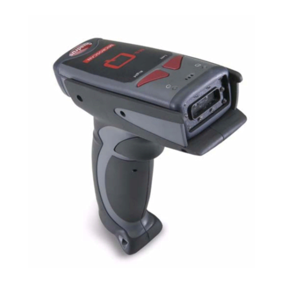
The MS-Q Imager, with point-and-click triggering, can read both 1D and 2D symbols and transfer (or buffer and transfer later) decoded data in both cable and wireless configurations. The MS-Q Imager is available in USB, RS-232, and PS/2 cabled options, a Batch option, and a Bluetooth option. - Page 8 Product Labels Product Labels The following labels are located on the MS-Q Quadrus Imager: (Bottom) (Top) (Inside Battery Bay) The following labels are located on the MS-Q Basic Imager: (Top) (Bottom) (Inside Battery Bay) viii MS-Q Imager User’s Manual...
-
Page 9: Statement Of Agency Compliance
The MS-Q has been tested by an independent electromagnetic compatibility laboratory in accordance with the applicable specifications and instructions. Laser/LED Radiation Wavelength: <1mW Maximum Output: 650-700 nm Laser Pulse Duration: 0.977 mSec. LED Pulse Duration: 0.255 uSec. MS-Q Imager User’s Manual... - Page 10 The information provided in this certification notice is correct to the best of Microscan’s knowledge at the date of publication. This notice is not to be considered a warranty or quality specification. Users are responsible for determining the applicability of any RoHS legislation or regulations based on their individual use of the product. MS-Q Imager User’s Manual...
- Page 11 In addition, a CB Test Certificate has been issued by the National Certification Board (NCB) indicating that the MS-Q meets all safety and quality standards in accordance with IEC 60950-1:2001, First Edition. MS-Q Imager User’s Manual...
- Page 12 Warning and Caution Summary MS-Q Imager User’s Manual...
- Page 13 Select Model..........................1-12 Select Protocol and Connect to Imager..................1-13 This section is designed to get your MS-Q Imager up and running quickly so you can get a sense of its capabilities and test sample symbols. Detailed setup information for configuring the imager for your specific application can be obtained in the subsequent sections.
-
Page 14: Check Required Hardware
Check Required Hardware Check Required Hardware Parts List for MS-Q Imagers with Cabled Handle (H2): • One MS-Q Imager • One H2 Handle • One 6 ft. USB cable (Quadrus models only) Note: PS/2 and RS-232 cables are optional and must be purchased separately. -
Page 15: Assemble The Imager
Quick Start Assemble the Imager To assemble the MS-Q Imager with Cabled Handle (H2): 1. Insert the flexible connector at the back of the H2 Handle into the MS-Q’s 8-pin DIN connector. Flexible Flexible Connector Connector 2. Snap the imager onto the H2 Handle over the battery blank. Be sure that the underside of the imager is latched at the front of the handle. - Page 16 Assemble the Imager To assemble the MS-Q Imager with Battery Handle: 1. Insert the tab on the back of the battery handle into the imager’s recessed slot at the base of the battery bay. 2. Snap the imager onto the battery handle over the battery. Be sure that the underside of the imager is latched at the front of the handle.
- Page 17 Quick Start To assemble the MS-Q Imager with Original Handle (H1): 1. Slide the imager into the handle’s cradle. Be sure the tabs fit into the grooves along the sides of the imager and that the handle’s 8-pin DIN connector inserts completely into the back of the unit.
-
Page 18: Usb Interface
60 seconds. If you connect with a battery blank installed, or if you install the battery after plugging in, no delay occurs. Clear Default Default Clear Save All Data Settings to USB to PS/2 Rules MS-Q Imager User’s Manual... -
Page 19: Ps/2 Interface
You are now ready to send data to the host. Important: The MS-Q must be connected to the keyboard for the imager and the keyboard to function in PS/2 Mode. Clear Default Default Clear Save All Data Settings to USB to PS/2 Rules MS-Q Imager User’s Manual... -
Page 20: Rs-232 Interface
RS-232 Default Settings Mode 8. Read the Save Settings symbol at the bottom of this page. You are now ready to send data to the host. Clear Default Default Clear Save All Data Settings to USB to PS/2 Rules MS-Q Imager User’s Manual... -
Page 21: Bluetooth Interface
Note: See Connecting to the Bluetooth Modem via RS-232 for instructions on how to use the Bluetooth Modem with a serial connection. Clear Default Default Clear Save All Data Settings to USB to PS/2 Rules MS-Q Imager User’s Manual... -
Page 22: Batch/Battery Interface
ERASED in the imager whenever you connect. You must have a data collection program open before connecting in Send and Buffer Mode or all buffered data will be lost. Save Settings 1-10 MS-Q Imager User’s Manual... -
Page 23: Install Esp
• Internet Explorer 5.0 or higher • 64 MB minimum RAM • 40 MB minimum disk space Important: The imager must be in one of the modes below to communicate with ESP. Connect Mode RS-232 Connect RS-232 Mode 1-11 MS-Q Imager User’s Manual... -
Page 24: Select Model
ESP, uncheck “Show this dialog at startup”. 2. Select the default reader name (MS-Q-1), or type a name of your choice in the Description text field and click OK. 3. Click Yes when this dialog appears: 1-12 MS-Q Imager User’s Manual... -
Page 25: Select Protocol And Connect To Imager
You can also check the Force Connect box and then click the Connect button. You are now ready to configure your imager using ESP. Subsequent sections provide more detailed information about ESP’s configuration options. 1-13 MS-Q Imager User’s Manual... - Page 26 You are now ready to configure your imager using ESP. Subsequent sections provide more detailed information about ESP’s configuration options. 1-14 MS-Q Imager User’s Manual...
-
Page 27: Using Esp
(Communications, Read Cycle, Symbologies, I/O Parameters, an Imager setup interface, a Terminal interface, and a Utilities interface). ESP can be used to configure the MS-Q Imager in the following ways: • Tree Controls: Each configuration menu contains a list of all option settings that pertain to that specific element of imager operation. -
Page 28: Ez Mode
Double click this image to view it in a larger format. Click Save Image to save it to a location of your choice. MS-Q Imager User’s Manual... -
Page 29: Application Mode
Assign Preamble and Postamble characters using the simple interface shown above. Note: For specific information on any of the icons shown above in the operations bar or configuration bar, see corresponding chapters in this manual. MS-Q Imager User’s Manual... -
Page 30: Tree Controls
5. Right click on the open screen and select Save to Reader to implement the command in the imager. The imager must be in one of the modes below to communicate with ESP. Connect Mode RS-232 Connect RS-232 Mode MS-Q Imager User’s Manual... -
Page 31: Menu Toolbar
ESP and the host hard drive. (Save to Imager) (Receive Reader Settings) Import / Export Import converts the ASCII settings from a text file to ESP configuration settings. Export converts the active ESP configuration settings to an ASCII text file. MS-Q Imager User’s Manual... - Page 32 To connect to another model, select New Model, choose the model you want, and click OK. All models you have selected and enabled will continue to appear in the dropdown model menu. The New Model option is repeated when you click the Switch Model button on the top row of icons. MS-Q Imager User’s Manual...
- Page 33 Sets the toolbar to display icons and names of all operations. Only Show Icon Sets the toolbar to display only icons representing operations, without text. Only Show Text Sets the toolbar to display names of operations only, without icons. MS-Q Imager User’s Manual...
- Page 34 Note: The F1 key is reserved for opening ESP Help and the F3 key is reserved for the Find Next function. Change Font Sets the font characteristics for data received from the imager. Change Echo Font Sets the font characteristics of user-entered data. MS-Q Imager User’s Manual...
- Page 35 Using ESP Bar Code Options Tab Sizing Information Sets element size (in thousands of an inch) of symbols that you create and print from the Bar Code Dialog under View. MS-Q Imager User’s Manual...
-
Page 36: Advanced Tab
Do Not Send or Receive Settings creates a condition in which Auto Sync will not send imager settings to ESP, or send ESP settings to the imager. Send XON with Auto-Connect Sends an XON (Begin Transmission) command to the imager before starting the Auto-Connect routine. 2-10 MS-Q Imager User’s Manual... - Page 37 Note: Memos must be saved in a .esp file if you want them to available in your next session. If you do not save your current session, any memos that you have entered during the session will be discarded, and will be unavailable in your next session. 2-11 MS-Q Imager User’s Manual...
- Page 38 Settings allows you to set baud rate, parity, stop bits, data bits and communications port for the RS-232 interface before connecting. Options allows you to auto-connect to the imager (RS-232), follow standard connection procedure (RS-232 and USB), and disconnect the imager from ESP (RS-232 and USB). 2-12 MS-Q Imager User’s Manual...
- Page 39 The View menu also allows you to access the Barcode Dialog. Barcode Dialog In the Barcode Dialog you can directly type the text and commands you want to encode. This allows you to create configuration symbols that you can print and read with the imager. 2-13 MS-Q Imager User’s Manual...
-
Page 40: Send/Receive
ESP settings if you choose to receive settings from the imager. Save to Reader Send, No Save This saves ESP settings to current memory. Send and Save This activates all changes in current memory and saves to the imager. 2-14 MS-Q Imager User’s Manual... - Page 41 Reader > Send No Save except that only the commands in the current menu tree are sent. Send Current Command This is the same as Send Current View above, but only saves the command that is currently selected. 2-15 MS-Q Imager User’s Manual...
- Page 42 Send/Receive 2-16 MS-Q Imager User’s Manual...
-
Page 43: Basic Operations
This section explains how to practice targeting and triggering, how to begin configuring the imager, how to perform a hardware default, and how to switch between Quadrus Only and Standard modes. (Mode switching is available for MS-Q Quadrus models only.) MS-Q Imager User’s Manual... -
Page 44: Step 1 Practice Targeting
• The imager is omnidirectional and can read a symbol from any position (The exception to this is with certain linear symbols; in these cases, the read area will be oriented to the length of the symbol.) Clear Default Default Clear Save All Data Settings to USB to PS/2 Rules MS-Q Imager User’s Manual... -
Page 45: Step 2 Determine Optimum Position
Select Adaptive or Fixed Mode on page 3-5). • For a more advanced setup, see Trigger Optimization on page 7-7. Test Symbol ABCDEFGHIJKLMNOP Clear Default Default Clear Save All Data Settings to USB to PS/2 Rules MS-Q Imager User’s Manual... -
Page 46: Step 3 Select Quadrus Only Or Standard Mode
Step 3 — Select Quadrus Only or Standard Mode This feature is available for MS-Q Quadrus models only. The firmware in the MS-Q Imager allows you to toggle easily between the specialized Quadrus Only Mode that is preferred for DPM (Direct Part Marking) or the more generalized Standard Mode. -
Page 47: Step 4 Select Adaptive Or Fixed Mode
Adaptive Mode. MS-Q settings can also be locked and unlocked by reading the following symbols: Test Symbol MS-Q Settings Locked MS-Q Settings Unlocked ABCDEFGHIJKLMNOP Clear Default Default Clear Save All Data Settings to USB to PS/2 Rules MS-Q Imager User’s Manual... -
Page 48: Step 5 Complete Configuration
Quadrus Only and Standard Modes. Left Right Test Symbol Indicator Indicator ABCDEFGHIJKLMNOP Left Right Button Button Clear Default Default Clear Save All Data Settings to USB to PS/2 Rules MS-Q Imager User’s Manual... -
Page 49: Trigger And Button Programming
Far Field Only Both Fields (Default) Near Field Only Continuous Read Both Fields Far Field Only Near Field Only Continuous Read Disabled (Default) Clear Default Default Clear Save All Data Settings to USB to PS/2 Rules MS-Q Imager User’s Manual... -
Page 50: Usb Battery Charge Mode
USB Battery Charge Mode USB Battery Charge Mode If you choose to charge the MS-Q Imager’s battery with a USB connection, you have the option of using USB Battery Charge Mode. This mode dedicates most of the power available from the USB connection to charging the battery. Read the symbol below to enable this mode. -
Page 51: Communications
Preamble and Postamble by ESP ....................4-22 Keyboard Mapping ........................4-23 Text Commands ......................... 4-24 Time Stamp ..........................4-25 Other Communications Settings in ESP..................4-26 This section includes connection parameters and options for communicating with the MS-Q Imager in various interfaces. MS-Q Imager User’s Manual... -
Page 52: Communications By Esp
5. Right click on the open screen and select Save to on the setting. Reader to implement the command in the imager. MS-Q Imager User’s Manual... -
Page 53: Communications Overview
(SPP). Batch/Battery The MS-Q’s Batch Mode is intended for applications that require a portable reader. Scanned data is saved to the imager’s non-volatile memory, and can then be transferred to a host. MS-Q Imager User’s Manual... -
Page 54: Usb Interface
COM port. This mode requires installation of a USB Virtual COM driver. Contact your Microscan sales representative to request this driver, as well as installation instructions. Clear Default Default Clear Save All Data Settings to USB to PS/2 Rules MS-Q Imager User’s Manual... -
Page 55: Ps/2 Interface
PS/2. Important: The imager must be connected to the keyboard for the imager and the keyboard to function in PS/2 Keyboard Mode. Clear Default Default Clear Save All Data Settings to USB to PS/2 Rules MS-Q Imager User’s Manual... -
Page 56: Rs-232 Interface
Baud Rate is the rate at which the imager and host transfer data. It only needs to be changed if necessary to match the host setting. 1200 19.2K 2400 38.4K 57.6K (Default) 4800 115.2K 9600 Save Settings Clear Default Default Clear Save All Data Settings to USB to PS/2 Rules MS-Q Imager User’s Manual... - Page 57 This feature sets the amount of time a cabled MS-Q will be enumerated before entering Sleep Mode in order to charge the battery more quickly. Cabled Timeout - Cabled Timeout - Never (Default) 2 Hours (Default) Clear Default Default Clear Save All Data Settings to USB to PS/2 Rules MS-Q Imager User’s Manual...
-
Page 58: Bluetooth Interface
• The imager attempts to read another symbol. Another important thing to consider is Bluetooth access. You choose Private when you want to limit access to only one imager. You choose Shared when you want more than one imager to have continuous access. MS-Q Imager User’s Manual... - Page 59 Important: One-Way Mode is not supported by the Microscan Bluetooth modem. One-Way Mode is supported by most other Bluetooth modems (Belkin, for example). MS-Q Imager User’s Manual...
- Page 60 Always read the Save Settings symbol after changing connectivity options. Default RF Clear Default Default Clear Save All Data Settings to USB to PS/2 Rules 4-10 MS-Q Imager User’s Manual...
- Page 61 When Auto-Disconnect is Enabled, the MS-Q will disconnect whenever there is no data to send to the host. When there is data to send, the MS-Q will connect, send the data, and disconnect once again (Shared Access). 4-11 MS-Q Imager User’s Manual...
-
Page 62: Sleep Mode Timeout
Note: Increasing the amount of time before the imager times out will decrease battery life. Note: If the imager has power (USB cable, power cable, etc.) it will disconnect based on Cabled Timeout settings. Default RF Clear Default Default Clear Save All Data Settings to USB to PS/2 Rules 4-12 MS-Q Imager User’s Manual... - Page 63 This eliminates the need to Save Settings after reading the Quick Connect Code. Disable Auto-Save (Default) Enable Auto-Save Default RF Clear Default Default Clear Save All Data Settings to USB to PS/2 Rules 4-13 MS-Q Imager User’s Manual...
-
Page 64: Lockout Link Mode
Unlock Link symbol below. Follow the above instructions with the new imager to establish the new connection. Lockout Link Mode Unlock Link Clear Default Default Clear Save All Data Settings to USB to PS/2 Rules 4-14 MS-Q Imager User’s Manual... - Page 65 6. Read the symbol below to return to USB Bluetooth Mode, and then read the Save Settings symbol at the bottom of this page. USB Bluetooth Mode Clear Default Default Clear Save All Data Settings to USB to PS/2 Rules 4-15 MS-Q Imager User’s Manual...
-
Page 66: Batch/Battery
None 3 beeps a. When power is supplied via cable, the LED will remain green whenever the imager is active. Important: When the memory LED turns RED, you must download or data will be lost. 4-16 MS-Q Imager User’s Manual... - Page 67 Communications Batch Mode Options The MS-Q Imager features three different Batch Modes for applications requiring a portable imager. Batch Modes allow a user to save data to the imager’s non-volatile memory and later transfer that data to a host computer when connected, either by USB or RS-232 cable, or by Bluetooth.
-
Page 68: Transferring And Deleting Data
Batch/Battery Transferring and Deleting Data The MS-Q Imager has three different commands that can transfer data or delete data in memory. All data in memory is sent every time the Transfer All Data Transfer All symbol is read. Data Every time the Transfer New Data symbol is read, only the Transfer New data in memory that hasn’t been sent will be transferred. - Page 69 This will cause it to download collected data, and the data will be erased from memory. To disable this feature, read the RS-232 Batch (Cable Detect) symbol. Clear Default Default Clear Save All Data Settings to USB to PS/2 Rules 4-19 MS-Q Imager User’s Manual...
-
Page 70: Preamble
Space Tab (USB Only) Important: Use only with serial applications. Erase All Carriage Return Preamble Data Line Feed Note: To erase all preamble and postamble data, read the following symbol: Erase Preamble and Postamble Data 4-20 MS-Q Imager User’s Manual... -
Page 71: Postamble
USB or erase all PS/2 Keyboard postamble modes. data. Tab (RS-232 Only) Erase / None Note: To erase all postamble Erase Preamble and preamble and Postamble data, read the Data symbol at right: 4-21 MS-Q Imager User’s Manual... -
Page 72: Preamble And Postamble By Esp
Scroll through a list of all preamble in the text fields and selecting and postamble options, and then from the dropdown menu, click Insert. you can also click any of these preset buttons to set a preamble or postamble. 4-22 MS-Q Imager User’s Manual... -
Page 73: Keyboard Mapping
US English, Ctrl + Char. Leading 0 (Default) Leading 0 for Non-Printable ASCII Japanese French German Universal Keyboard Custom Keyboard Keyboard Mapping by ESP Clear Default Default Clear Save All Data Settings to USB to PS/2 Rules 4-23 MS-Q Imager User’s Manual... -
Page 74: Text Commands
Send. Once the magic sequence has been sent, you can send text commands from the same text field. Clear Default Default Clear Save All Data Settings to USB to PS/2 Rules 4-24 MS-Q Imager User’s Manual... -
Page 75: Time Stamp
Disable Time Stamp Clear XML Rules Example: 01014627:ABCDEFGHIJKLMNOP Day is: 01 Hour is: 01 Minutes are: 46 Seconds are: 27 Data is: ABCDEFGHIJKLMNOP Clear Default Default Clear Save All Data Settings to USB to PS/2 Rules 4-25 MS-Q Imager User’s Manual... -
Page 76: Other Communications Settings In Esp
The minimum retry count is 1, which represents the initial transmission. Host Acknowledgement Timeout The Host Acknowledgement Timeout is the amount of time (in seconds) that the imager will wait for an acknowledgement from the host before re-sending data. 4-26 MS-Q Imager User’s Manual... -
Page 77: Reconnect Timeout
When this feature is enabled, a second beep is emitted while reading the Bluetooth Quick Connect Code, but before the Bluetooth connection is established. When this feature is disabled, the second beep is emitted upon connection to the Bluetooth Modem. 4-27 MS-Q Imager User’s Manual... - Page 78 Other Communications Settings in ESP 4-28 MS-Q Imager User’s Manual...
-
Page 79: Symbologies
QR Code............................. 5-24 GS1 DataBar ..........................5-25 UPC/EAN/JAN..........................5-26 Symbology Identifier ........................5-27 This section describes the various symbol types that can be read and decoded by the imager. Symbologies are arranged alphabetically. http://www.aimglobal.org/standards/aimpubs.asp for additional information. MS-Q Imager User’s Manual... -
Page 80: Symbologies By Esp
4. Left click again on the open screen to complete the selection. 5. Right click on the open screen and select Save to Reader to implement the command in the imager. MS-Q Imager User’s Manual... -
Page 81: Aztec
Read the following symbols to enable/disable Aztec settings: Aztec On Aztec Off (Default) Aztec by ESP Sample Aztec Symbol Note: Aztec is available only in Standard Mode. Clear Default Default Clear Save All Data Settings to USB to PS/2 Rules MS-Q Imager User’s Manual... -
Page 82: Codabar
Sample Codabar Symbol Note: Codabar is available only in Standard Mode. Clear Default Default Clear Save All Data Settings to USB to PS/2 Rules MS-Q Imager User’s Manual... -
Page 83: Codablock F
Code 128 should be disabled when Codablock F is enabled. Sample Codablock F Symbol Note: Codablock F and Codablock A are available only in Standard Mode. Clear Default Default Clear Save All Data Settings to USB to PS/2 Rules MS-Q Imager User’s Manual... -
Page 84: Code 11
Enabled with 1 Checksum Digit and Stripped from Result Code 11 by ESP Note: “No Report” in ESP has the same meaning as “Stripped from Result”. Sample Code 11 Symbol Note: Code 11 is available only in Standard Mode. MS-Q Imager User’s Manual... -
Page 85: Code 39
Full ASCII Off (Default) Code 39 Narrow Margins On Code 39 Narrow Margins Off (Default) Code 39 Trioptic On Code 39 Trioptic Off Clear Default Default Clear Save All Data Settings to USB to PS/2 Rules MS-Q Imager User’s Manual... - Page 86 Code 39 Code 39 by ESP Sample Code 39 Symbol Sample Code 39 Trioptic Symbol Note: Code 39 is available only in Standard Mode. Clear Default Default Clear Save All Data Settings to USB to PS/2 Rules MS-Q Imager User’s Manual...
-
Page 87: Code 93
Code 93 On (Default) Code 93 Off Code 93 by ESP Sample Code 93 Symbol Note: Code 93 is available only in Standard Mode. Clear Default Default Clear Save All Data Settings to USB to PS/2 Rules MS-Q Imager User’s Manual... -
Page 88: Code 128
Code 128 Narrow Margins Off (Default) Code 128 by ESP Sample Code 128 Symbol Note: Code 128 is available only in Standard Mode. Clear Default Default Clear Save All Data Settings to USB to PS/2 Rules 5-10 MS-Q Imager User’s Manual... -
Page 89: Composite
Maximum Decodes per Read represents the maximum number of candidate symbols in the field of view that can be decoded during a read cycle. Note that decode speed will decrease as the Maximum Decodes per Read value is increased. Sample Composite Symbol Note: Composite is available only in Standard Mode. 5-11 MS-Q Imager User’s Manual... -
Page 90: Data Matrix
(For Low Contrast and Binarized Symbols) Disable Data Matrix Improvements Sample Data Matrix Symbol Sample Rectangular Data Matrix Symbol Data Matrix by ESP Clear Default Default Clear Save All Data Settings to USB to PS/2 Rules 5-12 MS-Q Imager User’s Manual... -
Page 91: Interleaved 2 Of 5
Interleaved 2 of 5 by ESP Sample Interleaved 2 of 5 Symbol Note: Interleaved 2 of 5 is available only in Standard Mode. Clear Default Default Clear Save All Data Settings to USB to PS/2 Rules 5-13 MS-Q Imager User’s Manual... -
Page 92: Maxicode
Read the following symbols to enable/disable Maxicode settings: Maxicode On Maxicode Off (Default) Maxicode by ESP Sample Maxicode Symbol Note: Maxicode is available only in Standard Mode. Clear Default Default Clear Save All Data Settings to USB to PS/2 Rules 5-14 MS-Q Imager User’s Manual... -
Page 93: Matrix 2 Of 5
Matrix 2 of 5 by ESP Sample Matrix 2 of 5 Symbol Note: Matrix 2 of 5 is available only in Standard Mode. Clear Default Default Clear Save All Data Settings to USB to PS/2 Rules 5-15 MS-Q Imager User’s Manual... -
Page 94: Micropdf417
Read the following symbols to enable/disable MicroPDF417 settings: MicroPDF417 On MicroPDF417 Off (Default) MicroPDF417 by ESP Sample MicroPDF417 Symbol Note: MicroPDF417 is available only in Standard Mode. Clear Default Default Clear Save All Data Settings to USB to PS/2 Rules 5-16 MS-Q Imager User’s Manual... -
Page 95: Msi Plessey
MSI Plessey On MSI Plessey Off (Default) MSI Plessey by ESP Sample MSI Plessey Symbol Note: MSI Plessey is available only in Standard Mode. Clear Default Default Clear Save All Data Settings to USB to PS/2 Rules 5-17 MS-Q Imager User’s Manual... -
Page 96: Nec 2 Of 5
NEC 2 of 5 Off (Default) NEC 2 of 5 by ESP Note: NEC 2 of 5 is available only in Standard Mode. Clear Default Default Clear Save All Data Settings to USB to PS/2 Rules 5-18 MS-Q Imager User’s Manual... -
Page 97: Pdf417
PDF417 On (Default) PDF417 Off MacroPDF417 On MacroPDF417 Off (Default) PDF417 by ESP Sample PDF417 Symbol Note: PDF417 is available only in Standard Mode. Clear Default Default Clear Save All Data Settings to USB to PS/2 Rules 5-19 MS-Q Imager User’s Manual... -
Page 98: Pharmacode
No Color, Standard Rules, Vertical Decode, Normal Direction Pharmacode On; Color, Relaxed Contrast, Vertical Decode, Normal Direction Pharmacode On; No Color, Standard Rules, Horizontal Decode, Reverse Direction Clear Default Default Clear Save All Data Settings to USB to PS/2 Rules 5-20 MS-Q Imager User’s Manual... - Page 99 Color, Relaxed Contrast, Horizontal Decode, Reverse Direction Pharmacode On; No Color, Standard Rules, Vertical Decode, Reverse Direction Pharmacode On; Color, Relaxed Contrast, Vertical Decode, Reverse Direction Pharmacode Off (Default) Pharmacode by ESP Note: Pharmacode is available only in Standard Mode. 5-21 MS-Q Imager User’s Manual...
-
Page 100: Postal Symbologies
Japan Post On Australian Post On KIX On Planet On Postnet On Postnet and Planet On Royal Mail On Disable All Postal Symbologies (Default) Clear Default Default Clear Save All Data Settings to USB to PS/2 Rules 5-22 MS-Q Imager User’s Manual... - Page 101 Postal Symbologies by ESP Sample Planet Symbol Sample Postnet Symbol Sample Royal Mail Symbol Note: Postal symbologies are available only in Standard Mode. Clear Default Default Clear Save All Data Settings to USB to PS/2 Rules 5-23 MS-Q Imager User’s Manual...
-
Page 102: Qr Code
Inverse and Micro QR On QR Code by ESP Sample QR Code Symbol Note: QR Code is available in both Quadrus Only and Standard modes. Clear Default Default Clear Save All Data Settings to USB to PS/2 Rules 5-24 MS-Q Imager User’s Manual... -
Page 103: Gs1 Databar
All DataBar Off (Default) GS1 DataBar by ESP Sample DataBar Limited Symbol Sample DataBar-14 Truncated Symbol Sample DataBar-14 Stacked Symbol Sample DataBar Expanded Symbol Sample DataBar-14 Symbol Note: GS1 DataBar is available only in Standard Mode. 5-25 MS-Q Imager User’s Manual... -
Page 104: Upc/Ean/Jan
Note: Unless necessary, enabling Narrow Margins are not recommended. UPC Extension On UPC Extension Off (Default) UPC/EAN/JAN by ESP Sample UPC-E Symbol Note: UPC/EAN/JAN is available only in Standard Mode. Clear Default Default Clear Save All Data Settings to USB to PS/2 Rules 5-26 MS-Q Imager User’s Manual... -
Page 105: Symbology Identifier
The Symbology Identifier feature can be disabled by reading the Clear XML Rules symbol. Enable Symbology Identifier Clear XML Rules Symbology Identifier by ESP Clear Default Default Clear Save All Data Settings to USB to PS/2 Rules 5-27 MS-Q Imager User’s Manual... - Page 106 Symbology Identifier 5-28 MS-Q Imager User’s Manual...
- Page 107 MS-Q Operational Feedback ......................6-5 Trigger and Button Programming....................6-6 Beep and Vibrate Settings ......................6-8 Automatic Gain Control (AGC)......................6-9 LightRay Optics...........................6-11 This section contains information on how to set your imager to the most efficient and effective parameters for your application. MS-Q Imager User’s Manual...
-
Page 108: I/O Parameters By Esp
2. Double click on the parameter and click once in the selection box to view options. 3. Place your cursor in the selection box, scroll down to the setting you want to change and click once on the setting. MS-Q Imager User’s Manual... -
Page 109: Laser Target
Note: Laser On Before Capture determines whether the laser target will be on or off just before the MS-Q captures and image, and is disabled by default. Clear Default Default Clear Save All Data Settings to USB to PS/2 Rules MS-Q Imager User’s Manual... -
Page 110: Illumination
Illumination Illumination The MS-Q Imager’s illumination system is Visible LEDs composed of four visible LEDs and six infrared (IR) LEDs as shown at right. Both visible and IR LEDs can be controlled independently. IR LEDs can also be set to low power. -
Page 111: Ms-Q Operational Feedback
= 0-20% battery capacity or no memory available. • BLUE = Bluetooth Mode The MS-Q also emits beeps and/or vibrates to indicate specific information to the user. Refer to the table above to better understand MS-Q feedback. MS-Q Imager User’s Manual... -
Page 112: Trigger And Button Programming
Near Field Only Far Field Only Handle Trigger Take Picture Left Button Programming Both Fields (Default) Near Field Only Far Field Only Left Button Take Picture Disable Left Button Enable Left Button Mode Switching (Quadrus Only / Standard) MS-Q Imager User’s Manual... - Page 113 The Button/Trigger Confirmation Time is the amount of time that a button, trigger, or combination of the trigger and/or buttons, must be held down before the imager recognizes that a triggering event has occurred. Clear Default Default Clear Save All Data Settings to USB to PS/2 Rules MS-Q Imager User’s Manual...
-
Page 114: Beep And Vibrate Settings
Note: Duration is the length of the beep in milliseconds with a configurable range of 0.000 to 2147483.750. Separation is the spacing in milliseconds between beeps, also with a configurable range of 0.000 to 2147483.750. Clear Default Default Clear Save All Data Settings to USB to PS/2 Rules MS-Q Imager User’s Manual... -
Page 115: Automatic Gain Control (Agc)
This feature gives the gain control time to adjust. Minimum Exposure Minimum Exposure is a percentage value that represents the minimum exposure allowed for image captures. Maximum Exposure Maximum Exposure is a percentage value that represents the maximum exposure allowed for image captures. MS-Q Imager User’s Manual... - Page 116 Maximum Gain is a percentage value that represents the maximum gain adjustment allowed for decoder or imager AGC. Gain Break Point Gain Break Point is a percentage value that represents the point at which the imager stops automatic gain adjustment. 6-10 MS-Q Imager User’s Manual...
-
Page 117: Lightray Optics
FIS-6100-1024G LightRay 200 Series, Rev 6 Hardware Part Number MS-Q Quadrus, High Resolution, USB (PS/2, RS-232), LightRay 205 FIS-6100-2021G MS-Q Quadrus, High Resolution, Batch/Battery, LightRay 205 FIS-6100-2022G MS-Q Quadrus, High Resolution, Bluetooth, LightRay 205 FIS-6100-2023G 6-11 MS-Q Imager User’s Manual... - Page 118 Assembly (200 Series) • Place the 200 Series LightRay Optics attachment over the face of the MS-Q Imager. • The plastic body of the LightRay Optic device should be pressed firmly against the face of the imager, allowing minimum slippage.
- Page 119 • For best results, begin triggering before the LightRay Optic has come in contact with the surface or substrate. • Position the symbol equidistant from both of the 200 Series LightRay Optic’s guides. Guides Symbol 6-13 MS-Q Imager User’s Manual...
- Page 120 LightRay Optics LightRay Optics by ESP The MS-Q Imager can also be configured and optimized for LightRay operation using ESP. Click on the series you are using. You can either use the radio buttons (“100 Series” and “200 Series”) or click directly on the pictures.
- Page 121 Button Stay-Down Time......................7-22 Mirroring ............................. 7-23 Motion Detection......................... 7-24 Auto White Balance ........................7-25 Symbol Readability Index ......................7-26 This section introduces several settings that can be applied to speed up processing or improve readablility in various circumstances. MS-Q Imager User’s Manual...
-
Page 122: Dual Optics
Dual Optics Dual Optics The MS-Q Imager’s dual field optical system can read small 2D symbols as well as larger 1D symbols. It decodes the near and far fields simultaneously. The near field lens is for smaller symbols (optimal focal point: 4 inches) and the far field lens is for larger symbols (optimal focal point: 9 inches). -
Page 123: Vga And Megapixel Settings
VGA settings are not recommended for decoding high-density symbols. Important: VGA is only supported in Rev 5 hardware and earlier. Enable VGA (640 x 480) Enable SXGA (1280 x 1024) Clear Default Default Clear Save All Data Settings to USB to PS/2 Rules MS-Q Imager User’s Manual... -
Page 124: Select Region Of Interest
Large 2-Dimensional Symbols (512 x 512 pixels) (640 x 640 pixels) Default 2-Dimensional Symbols (1024 x 640 pixels) Casts the broadest possible FOV. Clear Default Default Clear Save All Data Settings to USB to PS/2 Rules MS-Q Imager User’s Manual... -
Page 125: Set Targeting Zone Tolerances
50% tolerance, you will need to aim the laser target so that the spot is directly on the candidate symbol. Read one of the symbols below to set the desired tolerance. 1600 (Default) Clear Default Default Clear Save All Data Settings to USB to PS/2 Rules MS-Q Imager User’s Manual... -
Page 126: Ip Modes
Standard Mode Standard Mode, while not recommended for DPM applications, can be applied to most symbologies. Clear Default Default Clear Save All Data Settings to USB to PS/2 Rules MS-Q Imager User’s Manual... -
Page 127: Trigger Optimization
See Optimization Parameters for more detailed explanations of each setting, and for examples of conditions in which you would use each setting (page 7-13). MS-Q Imager User’s Manual... - Page 128 Optimization Parameters for more detailed explanations of each setting, and for examples of conditions in which you would use each setting (page 7-13). Clear Default Default Clear Save All Data Settings to USB to PS/2 Rules MS-Q Imager User’s Manual...
-
Page 129: Handle Trigger Programming
Low Density Symbols Near and Far Field Near Field Far Field Region of Interest Fast Processing (VGA Mode) Handle Trigger Programming Near Field Only Both Fields (Default) Handle Trigger Take Picture Far Field Only Disable Handle Trigger MS-Q Imager User’s Manual... - Page 130 Region of Interest Fast Processing (VGA Mode) Left Button Programming Both Fields (Default) Near Field Only Far Field Only Left Button Take Picture Disable Left Button Enable Left Button Mode Switching (Quadrus Only / Standard) 7-10 MS-Q Imager User’s Manual...
- Page 131 Low Density Symbols Near and Far Field Near Field Far Field Region of Interest Fast Processing (VGA Mode) Right Button Programming Both Fields (Default) Near Field Only Far Field Only Right Button Take Picture Disable Right Button 7-11 MS-Q Imager User’s Manual...
- Page 132 Region of Interest Fast Processing (VGA Mode) Continuous Trigger Programming Far Field Only Both Fields Near Field Only Disable Continuous Trigger (Default) Clear Default Default Clear Save All Data Settings to USB to PS/2 Rules 7-12 MS-Q Imager User’s Manual...
- Page 133 (Rev 5 hardware speed available. and earlier only.) Note: See the Optimization Guide for definitions of optimization terminology (page 7-7). 7-13 MS-Q Imager User’s Manual...
- Page 134 (Rev 5 hardware and earlier only.) fast decodes than reliability. Note: See the Optimization Guide for definitions of optimization terminology (page 7-7). 7-14 MS-Q Imager User’s Manual...
-
Page 135: Trigger Optimization By Esp
Note: VGA Fast Processing settings B3, C3, and D3 are shown here when a Rev 5 (or earlier) MS-Q model is connected. VGA settings are not supported in Rev 6 MS-Q models. The Configuration Status display shows current settings for each trigger or button. 7-15 MS-Q Imager User’s Manual... - Page 136 Choose which trigger or button to optimize from this dropdown menu. Each trigger optimization option corresponds with a setting on the Optimization Guide (page 7-7). The Configuration Status display shows current settings for each trigger or button. 7-16 MS-Q Imager User’s Manual...
- Page 137 Trigger/Button Summary The Trigger/Button Summary view has the same Configuration Status information as the other two views, but it supplements that information with a diagram of the MS-Q Imager. This graphic interface orients the user to the location of the imager’s handle trigger and...
-
Page 138: Continuous Operations
Read one of the symbols below to set the amount of time the uncabled imager will operate in Continuous Read before entering Sleep Mode. Uncabled - 15 Minutes Uncabled - 5 Minutes (Default) Uncabled - 30 Minutes 7-18 MS-Q Imager User’s Manual... - Page 139 0 Seconds 1 Second 3 Seconds (Default) Continuous Read, Duplicate Read Delays 0 Seconds 1 Second 3 Seconds (Default) Continuous Read Off (Default) Clear Default Default Clear Save All Data Settings to USB to PS/2 Rules 7-19 MS-Q Imager User’s Manual...
-
Page 140: Symbol Background
Reverse Background On (Default) Reverse Background Off Sample Data Matrix Symbol (Light Background) Sample Data Matrix Symbol (Dark Background) Clear Default Default Clear Save All Data Settings to USB to PS/2 Rules 7-20 MS-Q Imager User’s Manual... -
Page 141: Set Decode Time
Short Decode Time Normal Decode Time (Default) (approx. 375 mS) Long Decode Time (approx. 675 mS) Extra Long Decode Time (approx. 750 mS) Clear Default Default Clear Save All Data Settings to USB to PS/2 Rules 7-21 MS-Q Imager User’s Manual... -
Page 142: Button Stay-Down Time
“decode symbol” event. The imager will behave as if the trigger is being activated for this specified amount of time. Available Button Stay-Down Time values are 0.000 to 2147483.750 (in seconds). 7-22 MS-Q Imager User’s Manual... -
Page 143: Mirroring
When Image Transform is set to Standard, Mirrored Image is disabled. When Image Transform is set to Mirrored Image, the MS-Q’s optics reverse the captured image before attempting to decode. Clear Default Default Clear Save All Data Settings to USB to PS/2 Rules 7-23 MS-Q Imager User’s Manual... -
Page 144: Motion Detection
The MS-Q’s sensitivity to motion in the field of view can be configured as shown below. Note: The lower the number, the greater the sensitivity. Clear Default Default Clear Save All Data Settings to USB to PS/2 Rules 7-24 MS-Q Imager User’s Manual... -
Page 145: Auto White Balance
Advanced Operations Auto White Balance When Auto White Balance is enabled, the MS-Q performs an automatic white balance routine, much like a digital camera. Light and dark values are optimized to improve decode performance. 7-25 MS-Q Imager User’s Manual... -
Page 146: Symbol Readability Index
Symbol Readability Index The Symbol Readability Index provides a measurement of a specific symbol’s readability. It is specific to the MS-Q Imager and should not be confused with a verification quality measurement. The Symbol Readability Index is a blend of information obtained from the internal operations of the decoding algorithm relating to contrast, symbology construct, error detection, forward error correction (if applicable), and other symbology-specific characteristics. - Page 147 8 Terminal Contents Terminal View..........................8-2 Find ...............................8-3 Send ..............................8-4 Macros............................8-5 Terminal Right-Click Menu ......................8-6 Terminal Dropdown Menu ......................8-7 This section describes the Terminal interface and macro functions in ESP. MS-Q Imager User’s Manual...
-
Page 148: Terminal View
Send text field. The Terminal view also displays symbol data or information from the imager. You can also right click on the Terminal screen to bring up a menu of further options. MS-Q Imager User’s Manual... -
Page 149: Find
1. Type “ABC” into the Find box. 2. Press Enter. The first instance of “ABC” will be highlighted in the terminal window. 3. Click the Find button to the left of the text field to locate additional instances of “ABC”. MS-Q Imager User’s Manual... -
Page 150: Send
Once text commands are initiated, they are saved in a dropdown menu that can be accessed by clicking the arrow to the right of the text field. You can also send the current command repeatedly by clicking the Send button repeatedly. MS-Q Imager User’s Manual... -
Page 151: Macros
When you click the arrow next to a any macro and select Edit, the following dialog appears: You can edit an existing macro or type in the Macro Name text field and define it in the Macro Value text field. MS-Q Imager User’s Manual... -
Page 152: Terminal Right-Click Menu
<trigger character> and click OK. Then whenever Ctrl-F2 is keyed, the trigger character will start the read cycle. Note: This feature is also available from the Terminal Dropdown Menu and the Terminal tab of the Preferences dialog. MS-Q Imager User’s Manual... -
Page 153: Terminal Dropdown Menu
F3. • Find Previous locates the most recently occurring instance of the specified data string in the terminal. • Keyboard Macros brings up the Function Keys dialog, which allows you to create customized macro functions. MS-Q Imager User’s Manual... - Page 154 Terminal Dropdown Menu MS-Q Imager User’s Manual...
-
Page 155: Utilities
MS-Q settings that are not default settings; Firmware, where you can update your imager’s firmware; Bluetooth, which can produce a “Quick Connect” symbol from alphanumeric text input; and Advanced, which allows you to collect batch files for customized imager configuration and optimization. MS-Q Imager User’s Manual... -
Page 156: Image Upload
Start button to begin the image capture process. Image captures are displayed in the Far Field and Near Field windows, depending on which field is enabled (Far, Near, or Both). MS-Q Imager User’s Manual... -
Page 157: Device Control
• Delete Stored Errors erases all logged errors whether you have looked at them or not. • Reboot Reader refreshes the imager’s memory and functionality, returning it to the most recent configuration you have saved. • Delete Stored Results erases logged data. MS-Q Imager User’s Manual... -
Page 158: Differences From Default
• To save the Differences from Default report, either as plain text or as a tab-delimited text file, click Save As. • Click Send and Save to send the settings to the reader and save them, or Send to Reader to send the settings without saving them. MS-Q Imager User’s Manual... -
Page 159: Firmware
Application Code Version, Download the needed files Firmware Version, Boot Code directly to the imager by Version, and Radio Version. clicking the Start button. MS-Q Imager User’s Manual... - Page 160 Serial number Xap/i2300230006000010006664A0235-616001-16 Firmware version Radio version (Bluetooth) “A” indicates that running firmware is the application. “B” if bootloader. “02” is an internal ID. Clear Default Default Clear Save All Data Settings to USB to PS/2 Rules MS-Q Imager User’s Manual...
-
Page 161: Bluetooth
When you have completed entering the connect code, ESP will produce a Data Matrix symbol encoding that data. Print and save the symbol for future use. Clear Default Default Clear Save All Data Settings to USB to PS/2 Rules MS-Q Imager User’s Manual... -
Page 162: Advanced
The single Remove arrow functions in the same way as the Add arrow, except that it transfers files back to the batch archive. The double Remove arrow allows you to transfer all files simultaneously. MS-Q Imager User’s Manual... - Page 163 Non-UII Characters........................10-3 UII Mode Features........................10-4 Error Messaging ......................... 10-6 Valid Formats ..........................10-8 This section explains the structure and purpose of Unique Item Identifiers (UIIs) and how to configure the MS-Q Imager to read them. 10-1 MS-Q Imager User’s Manual...
-
Page 164: Uii Overview
Serial Format Part Indicator Trailer Identifier Number Header Number [)> {RS} DD {GS} DUNABCD {GS} PN098 / 76 {GS} SEQ123-AC {RS} {EOT} Trailer Data Element Data Element Data Element Trailer Character Separator Separator Character Separator 10-2 MS-Q Imager User’s Manual... -
Page 165: Non-Uii Characters
When a message stream in any of the three available formats is read by the imager, non-UII characters are omitted and the UII is sent to the host. (format 06) (format DD) (format 05) Imager Host 10-3 MS-Q Imager User’s Manual... -
Page 166: Uii Mode Features
UII-Only Enabled with UII-Only Error Messaging Enabled UII Enabled UII Enabled with Error UII Disabled (Default) with Pass Through Messaging and Pass Through Clear Default Default Clear Save All Data Settings to USB to PS/2 Rules 10-4 MS-Q Imager User’s Manual... - Page 167 Each of the UII Mode Settings can also be enabled in ESP’s I/O Parameters tree control or graphic interface. UII-Only Enabled with UII-Only Enabled Error Messaging UII Disabled UII Enabled with UII Enabled with Error Messaging and Pass Through Pass Through 10-5 MS-Q Imager User’s Manual...
-
Page 168: Error Messaging
Error message: “Invalid AI (or DI or TEI depending on format in use)” Lower Case Characters [)>{RS}05{GS}800406141411a0B9C3d6{RS}{EOT} Error message: “Invalid Characters in Data” Clear Default Default Clear Save All Data Settings to USB to PS/2 Rules 10-6 MS-Q Imager User’s Manual... - Page 169 The following symbol will read in UII with Pass Through mode, because Indicator the invalid compliance indicator suggests that the encoded characters form a non-UII message stream. Clear Default Default Clear Save All Data Settings to USB to PS/2 Rules 10-7 MS-Q Imager User’s Manual...
-
Page 170: Valid Formats
Encoded message stream: [)>{RS}06{GS}18SOCVA5674A36458{RS}{EOT} DI (Format 06) Decoded UII output: DOCVA5674A36458 Encoded message stream: [)>{RS}DD{GS}CAG987654{GS}SERMKJHUIYD{RS}{EOT} TEI (Format DD) Decoded UII output: D987654MKLJHUIYD Clear Default Default Clear Save All Data Settings to USB to PS/2 Rules 10-8 MS-Q Imager User’s Manual... -
Page 171: Appendices
Appendix E Hardware Default and Manual Battery Recharge ........... A-58 Appendix F MS-Q Quadrus Secure with Image Lock..............A-61 Appendix G MS-Q Protective Jacket ..................A-62 Appendix H MS-Q Battery Charger .................... A-63 Appendix I MS-Q Bluetooth Modem ................... A-65 Appendix J MS-Q Maintenance....................A-68 MS-Q Imager User’s Manual... -
Page 172: Appendix A General Specifications
Optional Interface: RS-232, Bluetooth Class 1 Radio at characteristics may vary at high temperatures or other 328’ (100m), PS/2 environmental extremes. Warranty–One year limited Image Output Options warranty on parts and labor. Extended warranty available. Format: JPEG, BMP, Image Lock MS-Q Imager User’s Manual... -
Page 173: Ms-Q Imager User's Manual
FIS-6100-2016G MS-Q Quadrus, High Resolution, USB (PS/2, RS-232), LightRay 205 (Rev 6 Hardware) FIS-6100-2021G MS-Q Quadrus, High Resolution, Batch/Battery, LightRay 205 (Rev 6 Hardware) FIS-6100-2022G MS-Q Quadrus, High Resolution, Bluetooth, LightRay 205 (Rev 6 Hardware) FIS-6100-2023G MS-Q Imager User’s Manual... -
Page 174: Appendix B Electrical Specifications
PS/2_DATA_UART_RX_USB_DM - PS/2 data to host or keyboard/ UART receive PIN 5 signal/ USB Data minus signal PIN 6 PS/2_CLK_KB - PS/2 clock signal to the keyboard PIN 7 ~TRIG - trigger from the handle PIN 8 GND - signal ground Shield Shield Ground MS-Q Imager User’s Manual... - Page 175 Appendices USB Cable Pinouts MS-Q Imager User’s Manual...
- Page 176 Electrical Specifications RS-232 Cable Pinouts MS-Q Imager User’s Manual...
- Page 177 Handle Trigger Opt. - B1 Handle Trigger Opt. - B2 Handle Trigger Opt. - B3 Handle Trigger Opt. - C1 Handle Trigger Opt. - C2 Clear Default Default Clear Save All Data Settings to USB to PS/2 Rules MS-Q Imager User’s Manual...
- Page 178 Left Button Opt. - C3 Right Button Opt. - B1 Right Button Opt. - A1 Right Button Opt. - A2 Right Button Opt. - A3 Clear Default Default Clear Save All Data Settings to USB to PS/2 Rules MS-Q Imager User’s Manual...
- Page 179 Laser Settings - On Laser Settings - Off Laser Settings - Medium Laser Settings - High Modem Setting: (80%) (100%) spx15200:8N1 Default to PS/2 Clear Default Default Clear Save All Data Settings to USB to PS/2 Rules MS-Q Imager User’s Manual...
-
Page 180: Appendix C Configuration Symbols
RS-232 Cabled Transfer All Data in Transfer Only Unsent Continuous Trigger Continuous Trigger Memory Data in Memory Optimization - A1 Optimization - A2 Clear Default Default Clear Save All Data Settings to USB to PS/2 Rules A-10 MS-Q Imager User’s Manual... - Page 181 RS-232 Interface - Data RS-232 Interface - RS-232 Interface - Baud Rate - 115200 Bits - 7 Baud Rate - 38400 Baud Rate - 57600 Clear Default Default Clear Save All Data Settings to USB to PS/2 Rules A-11 MS-Q Imager User’s Manual...
- Page 182 Bluetooth Bluetooth Radio - Time Bluetooth Radio - Time Enable Pairing RF Com Enable Out - 1 Hour Out - 2 Hours Clear Default Default Clear Save All Data Settings to USB to PS/2 Rules A-12 MS-Q Imager User’s Manual...
- Page 183 Time Out - Cabled - Continuous Read - Near Continuous Read - Far Continuous Read - Near Always and Far Fields Field Only Field Only Clear Default Default Clear Save All Data Settings to USB to PS/2 Rules A-13 MS-Q Imager User’s Manual...
- Page 184 Imager ID and Firmware Near Field Only Far Field Only Take Picture Handle Trigger - Near and Far Fields Preamble - Comma Postamble - Comma Clear Default Default Clear Save All Data Settings to USB to PS/2 Rules A-14 MS-Q Imager User’s Manual...
- Page 185 Separately - True Mapping Only Left Button - Near Field Left Button - Near and Left Button - Take Only Far Fields Picture Clear Default Default Clear Save All Data Settings to USB to PS/2 Rules A-15 MS-Q Imager User’s Manual...
- Page 186 Tolerances - 400 Tolerances - 1600 Time Stamp Settings - Time Stamp Settings - Text Commands - On Text Commands - Off Clear Default Default Clear Save All Data Settings to USB to PS/2 Rules A-16 MS-Q Imager User’s Manual...
- Page 187 Short Decode Time Preamble - Tab - RS-232 Postamble - Tab - (20% Shorter) No Read Display Off Serial Mode RS-232 Serial Mode Clear Default Default Clear Save All Data Settings to USB to PS/2 Rules A-17 MS-Q Imager User’s Manual...
- Page 188 Code 39 On Code 39 - Enable Enable Checksum and Data Matrix Inverse Off Checksum Strip from Result Data Matrix Inverse On Clear Default Default Clear Save All Data Settings to USB to PS/2 Rules A-18 MS-Q Imager User’s Manual...
- Page 189 Planet On Postal Symbologies - Postal Symbologies - Postal Symbologies - QR Code - Off Disable All Postnet On Royal Mail On Clear Default Default Clear Save All Data Settings to USB to PS/2 Rules A-19 MS-Q Imager User’s Manual...
- Page 190 DataBar-14 Stacked On DataBar Expanded On Aztec Off Aztec On Codabar Off Codabar On Codablock F Off Codablock F On Code 93 Off Clear Default Default Clear Save All Data Settings to USB to PS/2 Rules A-20 MS-Q Imager User’s Manual...
- Page 191 PDF417 On UPC Extension Off UPC Off UPC On UPC Narrow Margin UPC Narrow Margin UPC Extension On Disabled Enabled MicroPDF417 Off Clear Default Default Clear Save All Data Settings to USB to PS/2 Rules A-21 MS-Q Imager User’s Manual...
- Page 192 Modem - 9600 Baud Modem - 2400 Baud Modem - 19200 Baud Modem - 38400 Baud Modem - 57600 Baud Modem - 115200 Baud Clear Default Default Clear Save All Data Settings to USB to PS/2 Rules A-22 MS-Q Imager User’s Manual...
- Page 193 023000 013000 Set Time Stamp Value Set Time Stamp Value Set Time Stamp Value Set Time Stamp Value 043000 030000 033000 040000 Clear Default Default Clear Save All Data Settings to USB to PS/2 Rules A-23 MS-Q Imager User’s Manual...
- Page 194 113000 120000 Set Time Stamp Value Set Time Stamp Value Set Time Stamp Value Set Time Stamp Value 133000 140000 130000 143000 Clear Default Default Clear Save All Data Settings to USB to PS/2 Rules A-24 MS-Q Imager User’s Manual...
- Page 195 Set Time Stamp Value Set Time Stamp Value 213000 210000 220000 223000 Set Time Stamp Value Set Time Stamp Value 233000 Preamble STX 230000 Clear Default Default Clear Save All Data Settings to USB to PS/2 Rules A-25 MS-Q Imager User’s Manual...
- Page 196 Stripped from Result) Disable Code 128 Narrow Enable Code 128 Narrow Disable Code 39 Narrow Enable Code 39 Narrow Margin Margin Margin Margin Clear Default Default Clear Save All Data Settings to USB to PS/2 Rules A-26 MS-Q Imager User’s Manual...
- Page 197 RS-232 Enable Imager Top Buttons - Toggle Contin. Time Out - Default - 30 Replace All \\ with \ (PDF417) Responses Trigger On/Off Seconds Clear Default Default Clear Save All Data Settings to USB to PS/2 Rules A-27 MS-Q Imager User’s Manual...
- Page 198 Modem - 1200 Baud Modem - 1200 Baud Modem - 1200 Baud Modem - 1200 Baud Modem - 1200 Baud Modem - 1200 Baud Clear Default Default Clear Save All Data Settings to USB to PS/2 Rules A-28 MS-Q Imager User’s Manual...
- Page 199 Modem - 2400 Baud Modem - 2400 Baud Modem - 2400 Baud Modem - 2400 Baud Modem - 2400 Baud Modem - 2400 Baud Clear Default Default Clear Save All Data Settings to USB to PS/2 Rules A-29 MS-Q Imager User’s Manual...
- Page 200 Modem - 4800 Baud Modem - 4800 Baud Modem - 4800 Baud Modem - 4800 Baud Modem - 4800 Baud Modem - 9600 Baud Clear Default Default Clear Save All Data Settings to USB to PS/2 Rules A-30 MS-Q Imager User’s Manual...
- Page 201 Modem - 9600 Baud Modem - 9600 Baud Modem - 19200 Baud Modem - 19200 Baud Modem - 19200 Baud Modem - 19200 Baud Clear Default Default Clear Save All Data Settings to USB to PS/2 Rules A-31 MS-Q Imager User’s Manual...
- Page 202 Modem - 38400 Baud Modem - 19200 Baud Modem - 38400 Baud Modem - 38400 Baud Modem - 38400 Baud Modem - 38400 Baud Clear Default Default Clear Save All Data Settings to USB to PS/2 Rules A-32 MS-Q Imager User’s Manual...
- Page 203 Modem - 57600 Baud Modem - 57600 Baud Modem - 57600 Baud Modem - 57600 Baud Modem - 57600 Baud Modem - 57600 Baud Clear Default Default Clear Save All Data Settings to USB to PS/2 Rules A-33 MS-Q Imager User’s Manual...
- Page 204 Modem - 115200 Baud Modem - 115200 Baud Modem - 115200 Baud Modem - 115200 Baud Modem - 115200 Baud Modem - 115200 Baud Clear Default Default Clear Save All Data Settings to USB to PS/2 Rules A-34 MS-Q Imager User’s Manual...
- Page 205 RF Range Notification - RF Range Notification - Preset LED - Disable Preset LED - Enable Vibrate Beep Alternate OS Compatibility Alternate OS Compatibility Clear Default Default Clear Save All Data Settings to USB to PS/2 Rules A-35 MS-Q Imager User’s Manual...
- Page 206 US English Keyboard German Keyboard Japanese Keyboard Full Field Image Capture Map with Ctrl + Char. for Mapping Mapping (1280 x 1024) Non-Printable ASCII Clear Default Default Clear Save All Data Settings to USB to PS/2 Rules A-36 MS-Q Imager User’s Manual...
- Page 207 Stripped from Result Enable Micro QR Code PS/2 Interscan Delay - PS/2 Interscan Delay - Boot Mode Standard and Inverse 5 mS 10 mS Clear Default Default Clear Save All Data Settings to USB to PS/2 Rules A-37 MS-Q Imager User’s Manual...
- Page 208 Modem Pre-Emptible Modem Non-Pre-Emptible Enable Auto-Save Disable Auto-Save Enable Data Matrix Disable Data Matrix Last Bluetooth Last Bluetooth Improvements Improvements Address Address Clear Default Default Clear Save All Data Settings to USB to PS/2 Rules A-38 MS-Q Imager User’s Manual...
- Page 209 Error Messaging Right Buttons Pass Through UII Enabled with Error Messaging and Pass Through UII Disabled Disable 2-Symbol Read Enable 2-Symbol Read Clear Default Default Clear Save All Data Settings to USB to PS/2 Rules A-39 MS-Q Imager User’s Manual...
- Page 210 USB Battery Charge Mode Battery Charge Mode) Separately in Both Fields RS-232 Connect Mode USB Connect Mode Enable MIL-STD-130M Enable MIL-STD-130N RS-232 Default Settings Mode Clear Default Default Clear Save All Data Settings to USB to PS/2 Rules A-40 MS-Q Imager User’s Manual...
-
Page 211: Appendix D Configuration Symbol Reference List
Left Button Optimization - C3 M034_01 Left Button Optimization - D1 M035_01 Left Button Optimization - D2 M036_01 Left Button Optimization - D3 M037_01 Right Button Optimization - A1 M038_01 Right Button Optimization - A2 A-41 MS-Q Imager User’s Manual... - Page 212 M073_02 RS-232 Batch M074_02 RS-232 Cabled M075_01 Send and Buffer Mode M076_01 Send and Log Mode M077_02 Transfer All Data in Memory M078_02 Transfer Only Unsent Data in Memory M079_01 Continuous Trigger Optimization - A1 A-42 MS-Q Imager User’s Manual...
- Page 213 Beep Loud M113_01 Disable Pair, Auth., Encrypt M114_02 Disconnect from Bluetooth M115_01 Encrypt, Enable Pairing, Auth. M116_01 Inquire and Connect M117_01 Enable Pairing M118_01 RF Com Enable M119_01 Bluetooth Radio - Time Out - 1 Hour A-43 MS-Q Imager User’s Manual...
- Page 214 Handle Trigger - Take Picture M155_03 Handle Trigger - Far Field Only M156_03 Handle Trigger - Near Field Only M157_03 Handle Trigger - Near and Far Fields M159_02 Preamble - Comma M160_04 Postamble - Comma M161_04 Postamble - Enter A-44 MS-Q Imager User’s Manual...
- Page 215 Time Stamp Settings - Off M200_02 Time Stamp Settings - On M201_03 Enable SXGA - 1280 x 1024 M202_03 Enable VGA - 640 x 480 (Rev 5 hardware or earlier only) M203_01 Enable SXGA Handle Trigger A-45 MS-Q Imager User’s Manual...
- Page 216 Code 39 - Enable Checksum M238_01 Enable Checksum and Strip From Result M239_01 Data Matrix Inverse On M240_01 Data Matrix Inverse Off M241_01 Data Matrix Rectangle Off M242_01 Data Matrix Rectangle On M243_01 Interleaved 2 of 5 Off A-46 MS-Q Imager User’s Manual...
- Page 217 Codabar Off M275_01 Codabar On M276_01 Codablock F Off M277_01 Codablock F On M280_01 Code 93 Off M281_02 Code 93 On M282_01 Code 128 Off M283_01 Code 128 On M284_02 Composite Off M285_02 Composite On A-47 MS-Q Imager User’s Manual...
- Page 218 Modem - 9600 baud 7 E 1 M330_02 Imager ID Preamble M331_02 Imager ID Postamble M334_01 Set TimeStamp Value 010000 M335_01 Set TimeStamp Value 013000 M336_01 Set TimeStamp Value 020000 M337_01 Set TimeStamp Value 023000 A-48 MS-Q Imager User’s Manual...
- Page 219 M371_01 Set TimeStamp Value 193000 M372_01 Set TimeStamp Value 200000 M373_01 Set TimeStamp Value 203000 M374_01 Set TimeStamp Value 210000 M375_01 Set TimeStamp Value 213000 M376_01 Set TimeStamp Value 220000 M377_01 Set TimeStamp Value 223000 A-49 MS-Q Imager User’s Manual...
- Page 220 Enable Pharmacode - No Color, Standard Rules, Vert. Decode, Reverse Direction M416_01 Enable Pharmacode - Color, Relaxed Contrast, Vert. Decode, Reverse Direction M417_01 RS-232 Suppress Imager Responses M418_02 Default to RS-232 Factory Settings M419_01 RS-232 Enable Imager Responses A-50 MS-Q Imager User’s Manual...
- Page 221 M454_01 Modem - 2400 baud M455_01 Modem - 2400 baud M456_01 Modem - 2400 baud M457_01 Modem - 2400 baud M458_01 Modem - 2400 baud M459_01 Modem - 2400 baud M460_01 Modem - 2400 baud A-51 MS-Q Imager User’s Manual...
- Page 222 M494_01 Modem - 9600 baud M495_01 Modem - 9600 baud M496_01 Modem - 9600 baud M497_01 Modem - 9600 baud M498_01 Modem - 9600 baud M499_01 Modem - 9600 baud M500_01 Modem - 19200 baud A-52 MS-Q Imager User’s Manual...
- Page 223 M534_01 Modem - 57600 baud M535_01 Modem - 57600 baud M536_01 Modem - 57600 baud M537_01 Modem - 57600 baud M538_01 Modem - 57600 baud M539_01 Modem - 57600 baud M540_01 Modem - 57600 baud A-53 MS-Q Imager User’s Manual...
- Page 224 Append Symbology to Postamble M577_01 Save Settings Using “~” M578_01 Append “:” to Preamble - Serial Mode M579_02 Illumination Flash On Event M580_02 Illumination Constant On Event M581_01 RF Range Notification Off M582_01 RF Range Notification - Vibrate A-54 MS-Q Imager User’s Manual...
- Page 225 NEC 2 of 5 Off M673_01 NEC 2 of 5 On M674_01 Matrix 2 of 5 Off M675_01 Matrix 2 of 5 On M684_01 RF Factory Defaults M685_01 Interleaved 2 of 5 with Control Character Stripped from Result A-55 MS-Q Imager User’s Manual...
- Page 226 Disable Left Button Q012_01 Disable Right Button Q013_01 Disable Left and Right Buttons Q014_01 UII-Only Enabled Q015_01 UII-Only Enabled with Error Messaging Q016_01 UII Enabled with Pass Through Q017_01 UII Enabled with Error Messaging and Pass Through A-56 MS-Q Imager User’s Manual...
- Page 227 Laser Off, Control IR Separately in Both Fields Q028_01 Laser On, Control IR Separately in Both Fields Q029_01 RS-232 Connect Mode Q030_01 USB Connect Mode Q031_01 Enable MIL-STD-130M Q032_01 Enable MIL-STD-130N MS101_01 RS-232 Default Settings Mode A-57 MS-Q Imager User’s Manual...
-
Page 228: Appendix E Hardware Default And Manual Battery Recharge
3. Remove the battery. Note: If you are using a battery blank, you do NOT need to remove it when performing a hardware default. (Continued on next page) A-58 MS-Q Imager User’s Manual... - Page 229 The following symbols will allow you to clear the imager’s memory of commands, settings, XML rules, and other data: Clear XML Rules Clear Memory A-59 MS-Q Imager User’s Manual...
- Page 230 5. Default the imager. (See Performing a Hardware Default and Manual Battery Recharge on page A-58.) Note: For best results, charge the battery fully before you next use the imager. A-60 MS-Q Imager User’s Manual...
-
Page 231: Appendix F Ms-Q Quadrus Secure With Image Lock
Important: The MS-Q Quadrus Secure’s Image Lock function cannot be “turned off”; it is a permanent part of the imager’s feature set. Note: The MS-Q Quadrus Secure with Image Lock is available with USB connectivity. Contact your Microscan sales representative for further product details. A-61 MS-Q Imager User’s Manual... -
Page 232: Appendix G Ms-Q Protective Jacket
LEDs and optics from scratches, fractures, and other potential damage. The rubberized sleeve makes the main body of the imager virtually shock-proof. Note: The MS-Q Protective Jacket is only available with the original (H1) handle option. A-62 MS-Q Imager User’s Manual... -
Page 233: Appendix H Ms-Q Battery Charger
4. Attach the cable to the modem by aligning the 8-pin DIN connectors and pushing them together firmly. 5. Guide the cable through the opening at the end of the charger that is aligned with the 8-pin DIN connector. A-63 MS-Q Imager User’s Manual... - Page 234 Kit, Charging Bay for Battery Handle, USA Power Supply 98-000075-10 Kit, Charging Bay for Battery Handle, Europe Power Supply 98-000075-11 Kit, Charging Bay for Battery Handle, UK Power Supply 98-000075-12 Kit, Charging Bay for Battery Handle, No Power Supply 98-000075-13 A-64 MS-Q Imager User’s Manual...
-
Page 235: Appendix I Ms-Q Bluetooth Modem
The MS-Q Bluetooth Modem is an external modem designed to be connected to the host computer while using a Bluetooth-enabled MS-Q Imager. The modem enables the imager to transmit captured and decoded data wirelessly to the host computer. The modem can accommodate three different cable attachment types, as shown below. - Page 236 • Read the Quick Connect Code on the top label of the Bluetooth Modem, using the MS-Q Imager you intend to connect to the host computer. The imager and host computer should connect within 60 seconds. The MS-Q will beep...
- Page 237 Data Bits: 8 Parity: None 9600 (Default) 1200 2400 4800 Stop Bits: 1 Hardware: None You are now ready to begin sending decoded symbol data to the host, using any open software application that accepts serial data. A-67 MS-Q Imager User’s Manual...
-
Page 238: Appendix J Ms-Q Maintenance
The MS-Q housing may be cleaned in the same way. For applications that require cleaning with disinfectant, please use products with the following ingredients: • Isopropyl Alcohol • Ethyl Alcohol (Denatured Grade) Do not use bleach. A-68 MS-Q Imager User’s Manual... - Page 239 Hyperlink Index About the MS-Q Imager About This Manual Adaptive Mode Add Batch Files to Collection Add Macro Advanced Advanced Operations Advanced Options Advanced Preferences AGC Frame Adjust Count AGC Selection AI (Format 05) Always Ask Before Auto Sync Occurs...
- Page 240 Button Stay-Down Time Button/Trigger Confirmation Time Capture Text CE Standards Change Background Color Change Echo Font Change Font Change Keyboard Macros Check Required Hardware Clear Clear All Data Clear XML Rules Codabar Codabar by ESP Codablock by ESP MS-Q Imager User’s Manual...
- Page 241 Continuous Read, Duplicate Read Delays Continuous Read, Sleep Timeout Continuous Read, Trigger Delays Continuous Trigger Optimization Continuous Trigger Programming Copy Data Bits (RS-232) Data Element Separator Data Matrix Data Matrix by ESP Data Matrix ECC 0-140 Data Matrix Improvements MS-Q Imager User’s Manual...
- Page 242 Editing a Macro EID Too Long Electrical Electrical Specifications Enable Echo Encoding a UII Enhanced Format Entering Magic Sequence Enterprise Identifier (EID) Environmental Specifications Error Messaging ESP Optimization Matrix ESP System Requirements Expect Host Response EZ Mode Find MS-Q Imager User’s Manual...
- Page 243 Host Acknowledgement Timeout I/O Parameters I/O Parameters by ESP Illumination Image Output options Image Transform Image Upload Imager ID Import / Export Indicators Install ESP Installation Steps for Batch/Battery Installation Steps for Bluetooth Installation Steps for PS/2 MS-Q Imager User’s Manual...
- Page 244 LightRay Accessory Options LightRay Assembly (100 Series) LightRay Assembly (200 Series) LightRay Optics LightRay Optics by ESP LightRay Optics FIS Options LightRay Setup Limitation of Liability Lockout Link Mode (Bluetooth) Log Only Mode Lower Case Characters MS-Q Imager User’s Manual...
- Page 245 MS-Q Battery Charger Options MS-Q Imager MS-Q Imager Dimensions MS-Q Operational Feedback MS-Q Protective Jacket MS-Q Quadrus Secure with Image Lock Near/Far Fields NEC 2 of 5 NEC 2 of 5 by ESP New ESP File MS-Q Imager User’s Manual...
- Page 246 Performing a Hardware Default Pharmacode Pharmacode by ESP Postal Symbologies Postal Symbologies by ESP Postamble Practice Targeting Preamble Preamble and Postamble by ESP Private Access Product Labels PS/2 Communications PS/2 Configuration PS/2 Interface PS/2 Keyboard Mode PS/2 Mode MS-Q Imager User’s Manual...
- Page 247 RF One-Way Mode (Maximum Reliability) RF Two-Way Mode Right Button Right Button Optimization Right Button Programming Right Button Take Picture RS-232 Batch Features RS-232 Cable Pinouts RS-232 Communications RS-232 Configuration RS-232 Connect Mode RS-232 Hardware RS-232 Interface MS-Q Imager User’s Manual...
- Page 248 Settings / Options Shared Access Show Both Icon and Text (Default) Show Connect Prompt Show Model Prompt Show Non-Printable Characters Sizing Information Skip EZ Mode Sleep Mode Timeout Space in Data Qualifier Standard Mode Statement of Agency Compliance MS-Q Imager User’s Manual...
- Page 249 Transfer All Data Transfer All Data in Memory Transfer New Data Transferring and Deleting Data Tree Controls Trigger and Button Programming Trigger Character Trigger Optimization Trigger Optimization by ESP Trigger/Button Configuration Trigger/Button Summary UII Disabled (Default) UII Elements MS-Q Imager User’s Manual...
- Page 250 USB Virtual COM Mode Using ESP Utilities Valid Formats Valid UII Message Streams and UII Output VGA and Megapixel Settings VGA Imaging Area Vibrate/Beep View Visible LEDs Off and IR On Warning and Caution Summary Warranty Statement MS-Q Imager User’s Manual...
Need help?
Do you have a question about the MS-Q Imager and is the answer not in the manual?
Questions and answers