Sign In
Upload
Manuals
Brands
Intel Manuals
Server
SR1680MV - Server System - 0 MB RAM
Intel SR1680MV - Server System - 0 MB RAM Manuals
Manuals and User Guides for Intel SR1680MV - Server System - 0 MB RAM. We have
1
Intel SR1680MV - Server System - 0 MB RAM manual available for free PDF download: Service Manual
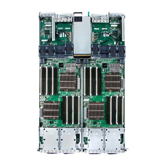
Intel SR1680MV - Server System - 0 MB RAM Service Manual (196 pages)
A Guide for Technically Qualified Assemblers of Intel Identified Subassemblies/Products
Brand:
Intel
| Category:
Server
| Size: 6.24 MB
Table of Contents
Preface
3
About this Manual
3
Manual Organization
3
Product Contents, Order Options, and Accessories
4
Additional Information and Software
4
Safety Information
7
Important Safety Instructions
7
Consignes de Sécurité
7
Wichtige Sicherheitshinweise
7
Instrucciones de Seguridad Importantes
7
Warnings
9
Table of Contents
11
Chapter 1: Server System Features
21
Figure 1. Intel ® Server System SR1680MV with 2.5-Inch Pluggable Hdds
21
Table 1. Intel ® Server System SR1680MV Feature Summary
22
System Overview
23
Server Chassis Layout
23
Figure 2. Layout of Server Chassis with 2.5-Inch Pluggable Hdds
23
Front View Components
24
Back View Components
24
Figure 3. Front View of Server with 2.5-Inch Pluggable Hdds
24
Buttons and System Leds
25
Front Panel Buttons and Leds
25
Figure 4. Back View
25
Figure 5. Front Panel Buttons and Leds of Server
25
Rear Panel Button and Leds
26
LED Information
26
Figure 6. Back View Leds and Buttons of Two I/O Boards
26
Table 2. LED Information
26
Chapter 2: Hardware Installations and Upgrades
29
Before You Begin
29
Tools and Supplies Needed
29
System References
30
Power off
30
Figure 7. Pressing the Power Button
30
MID-Top Cover
31
Removing the MID-Top Cover
31
Figure 8. Unplugging the Power Cord
31
Central Processing Unit (CPU)
32
Figure 9. Removing the MID-Top Cover
32
Figure 10. Location of Processors
32
Removing the Processor
33
Figure 11. Opening the Load Plate
33
Figure 12. Lifting the Processor out of the Socket
34
Figure 13. Placing on the Pnp Cap
34
Installing the Processor
35
Figure 14. Closing the Load Plate
35
Removing the Heatsink
36
Figure 15. Pointing the Golden Corner Toward the Socket
36
Installing the Heatsink
37
System Memory
37
Figure 16. Removing the Heatsink
37
Figure 17. Location of System Memories
38
Figure 18. DIMM Socket Location
38
System Memory Channel Population Requirements for Memory RAS Modes
39
Independent Channel Mode
39
Mirrored Channel Mode
39
Lockstep Channel Mode
39
Table 3. Ideal DIMM Installation Options for A-C Channels of Processor 1
40
Table 4. Ideal DIMM Installation Options for D-F Channels of Processor 2
40
Removing a DIMM
41
Installing a DIMM
41
Figure 19. Lifting the DIMM out of the Socket
41
Figure 20. Pressing the Retaining Clips Outward
42
Figure 21. Inserting the DIMM into the Socket
42
Server Board Cage Module
43
Figure 22. Server Board Cage Module with 2.5-Inch Pluggable SATA HDD Location
43
Figure 23. Releasing the Locking Latch
43
Figure 24. Pull the Locking Lever to Remove the Server Board Cage Module
44
Left and Right I/O Board Cage Modules
45
Figure 25. Left I/O Board Cage Module Location
45
Figure 26. Right I/O Board Cage Module Location
45
Figure 27. Slide the Locking Latch
46
Figure 28. Pull the Locking Lever to Remove the Left I/O Board Cage Module
46
Removing the Left I/O Board Cage Module
46
Power Supply Module
47
Removing the Power Supply Module
47
Figure 29. Power Supply Location
47
Installing the Power Supply Module
48
Power Distribution Board
48
Figure 30. Removing the Power Supply Module
48
Figure 31. Power Distribution Board
48
Figure 32. Removing the Power Distribution Board
49
Installing the Power Distribution Board
49
Removing the Power Distribution Board
49
Pluggable SATA Drive
50
2.5-Inch Pluggable SATA HDD
50
Removing a 2.5-Inch Pluggable SATA HDD
50
Figure 33. 2.5-Inch Pluggable SATA HDD Location
50
Figure 34. Release the Locking Lever
51
Figure 35. Pull the Locking Lever to Remove the HDD Carrier
51
Installing a 2.5-Inch Pluggable SATA HDD
52
2.5-Inch Pluggable HDD Backplane
52
Figure 36. Release Screws and Lift the HDD up
52
Figure 37. 2.5-Inch Pluggable HDD Backplane Location
52
Installing a 2.5-Inch Pluggable SATA HDD Backplane
53
Removing an HDD Backplane
53
System Fans
53
Figure 38. Remove the Screws and Lift the Backplane up
53
Figure 39. System Fans Location
54
Figure 40. Lift a System Fan up from I/O Board Cage Module
54
Removing a System Fan
54
Installing a System Fan
55
Air Duct
55
Removing the IOB Air Duct
55
Figure 41. Lift Air Duct up
55
Installing Air Ducts
56
PCI-E Cage
56
Removing a PCI-E Cage
56
Figure 42. PCI-E Cage Location
56
Figure 43. Lifting the PCI Cage from the I/O Board Module
57
Figure 44. Removing the Expansion Card
57
Installing a PCI-E Cage
58
Daughter Cards (Optional)
58
Figure 45. Securing the Slot Cover
58
Figure 46. Removing the Riser Card
58
Removing the IO Expansion Module
59
Figure 47. 10 GB IO Card Location
59
Figure 48. Infiniband Card Location
59
Figure 49. Lifting the Module Upward from the IO Board
60
Figure 50. Removing the Module Upward from the IO Board
60
Installing the IO Expansion Module
61
Chapter 3: Cable Connections
63
Connectors and Pin 1 Locations
63
Figure 51. Locations of Connectors and Pin 1 on Server Board
63
Cable Connections
64
Figure 52. Locations of Connectors and Pin 1 on I/O Board
64
Figure 53. Connecting the System Fan Cables
65
Chapter 4: Connectors, Jumpers, and Leds
67
Connector and Component Locations of Server Board
67
Figure 54. Connectors and Component Locations of Server Board
67
Connector and Component Locations of IO Board
69
Figure 55. Connectors and Component Locations of IO Boards
69
Connector and Component Locations of NIC Board
70
Figure 56. Connectors and Component Locations of NIC Board
70
Connectors and Components of Front Panel
71
Figure 57. Connectors and Component Locations of Front Panel
71
GB IO Card (Optional Daughter Card)
72
Figure 58. Connectors and Components of 10 GB IO Card
72
Infiniband Card (Optional Daughter Card)
73
Figure 59. Connectors and Components of Infiniband Card
73
Connector and Component Locations of HDD Backplane
74
Figure 60. Connectors and Components of 2.5-Inch Pluggable HDD Backplane
74
Connectors and Component Locations of PDB
75
Figure 61. Connectors and Component Locations of PDB
75
Figure 62. Location of MISC Jumper
76
Figure 63. Location of ich Function Jumper
77
Chapter 5: BIOS Setup and Configuration
79
BIOS Setup Utility
79
Table 5. BIOS Setup Utility Screen Descriptions
79
Entering the BIOS Setup Utility
80
Table 6. Keyboard Command Bar Description
80
Main Menu
83
Table 7. Main Menu of BIOS Setup Utility
83
Table 8. Main Menu Fields
83
Advanced Menu
84
Table 9. Advanced Menu of BIOS Setup Utility
84
Table 10. CPU Configuration Submenu
85
Table 11. CPU Configuration Submenu Fields
85
SATA Configuration Submenu
87
Table 12. SATA Configuration Submenu1
87
Table 13. SATA Configuration Submenu2
88
Table 14. SATA Configuration Submenu3
89
Table 15. SATA Configuration Submenu4
90
Table 16. SATA Configuration Submenu Fields
91
Table 17. Primary/Secondary IDE Master/Slave
92
Table 18. Primary/Secondary IDE Master/Slave Submenu Field
93
Super IO Chipset Submenu
94
Table 19. Super IO Chipset Submenu
94
Table 20. SATA Configuration Submenu Fields
95
USB Configuration Submenu
96
Table 21. USB Configuration Submenu
96
Table 22. USB Configuration Submenu Fields
96
USB Mass Storage Device Configuration Submenu
98
Table 23. USB Mass Storage Device Configuration Submenu
98
Table 24. USB Mass Storage Device Configuration Submenu Fields
99
PCI Express* Configuration Submenu
100
Table 25. PCI Express* Configuration Submenu
100
Table 26. PCI Express* Configuration Submenu Fields
100
IPMI Configuration Submenu
101
Table 27. IPMI Configuration Submenu
101
Table 28. IPMI Configuration Submenu Fields
102
View BMC System Event Log Submenu
103
Table 29. View BMC System Event Log Submenu
103
Remote Access Configuration Submenu
104
Table 30. Remote Access Configuration Submenu
104
Table 31. Remote Access Configuration Submenu Fields
104
Boot Menu
105
Table 32. Boot Menu of BIOS Setup Utility
105
Boot Setting Configuration Submenu
106
Table 33. Boot Setting Configuration Submenu of BIOS Setup Utility
106
Table 34. Boot Setting Configuration Submenu Fields
106
Boot Device Priority Submenu
108
Table 35. Boot Device Priority Submenu
108
Removable Drives Submenu
109
Table 36. Removable Drives Submenu
109
CD/DVD Drives Submenu
110
Table 37. CD/DVD Drives Submenu
110
Security Menu
111
Table 38. Security Menu of BIOS Setup Utility
111
Table 39. Security Menu Fields
112
Trusted Computing Submenu
113
Table 40. Trusted Computing Submenu
113
Table 41. Trusted Computing Submenu Fields
114
Exit Menu
115
Table 42. Exit Menu of BIOS Setup Utility
115
BIOS Updates
116
ROM Flash
116
Table 43. BIOS Requirements Description
116
Chapter 6: Embedded SATA RAID
119
Enabling RAID in the BIOS Setup
119
Chapter 7: Installing the Rackmount Rail Kits
121
Figure 64. Overview of Rail Kit
121
Table 44. Recommended Screwdrivers
121
Figure 65. Location of Spring Screw Holes
122
Procedure to Install the Rail Kit
122
Table 45. Location and Adapt Depth for Racks
122
Figure 66. Secure Screw into the Rail Hole
123
Figure 67. Secure the Rail to Racks
123
Figure 68. Slide the Server into Racks
123
Figure 69. Push the Server to the End of Racks
124
Figure 70. Secure the Server Ears to Racks
124
Appendix A: Intel Server Issue Report Form
125
System Information
125
Appendix B: Troubleshooting
131
Resetting the System
131
Problems Following Initial System Installation
131
First Steps Checklist
131
Table 46. Resetting the System
131
Hardware Diagnostic Testing
132
Verifying Proper Operation of Key System Lights
133
Confirming Loading of the Operating System
133
Specific Problems and Corrective Actions
133
Power Light Does Not Light
133
No Characters Appear on Screen
134
Characters Are Distorted or Incorrect
134
System Cooling Fans Do Not Rotate Properly
135
Cannot Connect to a Server
135
LED Information
136
BIOS POST Beep Codes
136
Table 47. LED Information
136
Table 48. POST Error Beep Codes
136
Table 49. Error Beep Codes Generated by Intel Management Module
137
Appendix C: Installation/Assembly Safety Instructions
139
English
139
Deutsch
141
Français
143
Español
145
Italiano
147
Appendix D: Safety Information
151
English
151
Server Safety Information
151
Safety Warnings and Cautions
151
Intended Application Uses
152
Site Selection
152
Equipment Handling Practices
152
Power and Electrical Warnings
153
Access Warnings
153
Electrostatic Discharge (ESD)
154
Other Hazards
154
Deutsch
155
Sicherheitshinweise für den Server
155
Sicherheitshinweise und Vorsichtsmaßnahmen
156
Zielbenutzer der Anwendung
156
Standortauswahl
156
Handhabung von Geräten
157
Warnungen zu Netzspannung und Elektrizität
158
Warnhinweise für den Systemzugang
158
Elektrostatische Entladungen (ESD)
159
Andere Gefahren
160
Français
161
Consignes de Sécurité Sur Le Serveur
161
Sécurité: Avertissements Et Mises en Garde
161
Domaines D'utilisation Prévus
162
Sélection D'un Emplacement
162
Pratiques de Manipulation de L'équipement
162
Alimentation Et Avertissements en Matière D'électricité
163
Avertissements Sur L'accès Au Système
163
Décharges Électrostatiques (ESD)
164
Autres Risques
164
Español
165
Información de Seguridad del Servidor
165
Advertencias y Precauciones sobre Seguridad
165
Aplicaciones y Usos Previstos
166
Selección de la Ubicación
166
Manipulación del Equipo
167
Advertencias de Alimentación y Eléctricas
167
Advertencias el Acceso al Sistema
168
Descarga Electrostática (ESD)
169
Otros Peligros
169
简体中文
171
Appendix E: Regulatory and Certification Information
177
Product Regulatory Compliance
177
Product Safety Compliance
178
Product EMC Compliance - Class a Compliance
178
Product Ecology Compliance
179
Certifications / Registrations / Declarations
179
Product Regulatory Compliance Markings
180
Table 50. Product Regulatory Compliance Markings
180
Rack Mount Installation Guidelines
185
Power Cord Usage Guidelines
186
Electromagnetic Compatibility Notices
188
FCC Verification Statement (USA)
188
ICES-003 (Canada)
189
CE Declaration of Conformity (Europe)
189
VCCI (Japan)
189
BSMI (Taiwan)
190
KCC (Korea)
190
Regulated Specified Components
190
Appendix F: Warranty
193
Appendix G: Getting Help
195
Advertisement
Advertisement
Related Products
Intel SR1630BC - Server System - 0 MB RAM
Intel SR1625UR - Server System - 0 MB RAM
Intel SR1630GP - Server System - 0 MB RAM
Intel SR1630HGP - Server System - 0 MB RAM
Intel SR1600UR - Server System - 0 MB RAM
Intel SR1695GPRX
Intel SR1600URHS
Intel SR1625URSAS
Intel SR1695WB
Intel SR1550ALRNA - Server System - 0 MB RAM
Intel Categories
Motherboard
Computer Hardware
Server
Server Board
Desktop
More Intel Manuals
Login
Sign In
OR
Sign in with Facebook
Sign in with Google
Upload manual
Upload from disk
Upload from URL