Table of Contents
Advertisement
Quick Links
Cat. No. I533-E1-04
SMARTSTEP A SERIES
R7M-A@ (Servomotors)
R7D-AP@ (Servo Drivers)
Servomotors/Servo Drivers
USER'S MANUAL
Advertisement
Table of Contents
Troubleshooting

Subscribe to Our Youtube Channel
Related Manuals for Omron SMARTSTEP R7D-AP Series


Summary of Contents for Omron SMARTSTEP R7D-AP Series
- Page 1 Cat. No. I533-E1-04 SMARTSTEP A SERIES R7M-A@ (Servomotors) R7D-AP@ (Servo Drivers) Servomotors/Servo Drivers USER’S MANUAL...
- Page 2 2. The products are illustrated without covers and shieldings for closer look in this USER'S MANUAL. For actual use of the products, make sure to use the covers and shieldings as specified. 3. This USER'S MANUAL and other related user's manuals are to be delivered to the actual end users of the products.
- Page 3 USER’S MANUAL SMARTSTEP A SERIES MODELS R7M-A@ (Servomotors) R7D-AP@ (Servo Drivers) Servomotors/Servo Drivers...
- Page 5 OMRON, 2001 All rights reserved. No part of this publication may be reproduced, stored in a retrieval system, or transmitted, in any form, or by any means, mechanical, electronic, photocopying, recording, or otherwise, without the prior written permission of OMRON.
- Page 7 This manual may include illustrations of the product with protective covers removed in order to describe the components of the product in detail. Make sure that these protective covers are on the product before use. Consult your OMRON representative when using the product after a long period of storage.
- Page 8 Installation and Wiring Precautions !Caution Do not step on or place a heavy object on the product. Doing so may result in injury. !Caution Do not cover the inlet or outlet ports and prevent any foreign objects from entering the product.
- Page 9 When an alarm occurs, remove the cause, reset the alarm after confirming safety, and then resume operation. Not doing so may result in injury. !Caution Do not use the built-in brake of the Servomotor for ordinary braking. Doing so may result in malfunction.
- Page 10 Maintenance and Inspection Precautions !WARNING Do not attempt to disassemble, repair, or modify any Units. Any attempt to do so may result in malfunction, fire, or electric shock. !Caution Resume operation only after transferring to the new Unit the contents of the data...
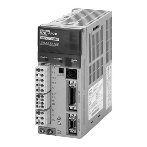
- Page 11 Warning Labels Warning labels are pasted on the product as shown in the following illustration. Be sure to follow the instructions given there. Warning label Example from R7D-AP01L Example from R7D-AP01L...
- Page 13 WHETHER SUCH CLAIM IS BASED ON CONTRACT, WARRANTY, NEGLIGENCE, OR STRICT LIABILITY. In no event shall the responsibility of OMRON for any act exceed the individual price of the product on which liability is asserted. IN NO EVENT SHALL OMRON BE RESPONSIBLE FOR WARRANTY, REPAIR, OR OTHER CLAIMS...
- Page 14 The following are some examples of applications for which particular attention must be given. This is not intended to be an exhaustive list of all possible uses of the products, nor is it intended to imply that the uses listed may be suitable for the products: •...
- Page 15 PERFORMANCE DATA Performance data given in this manual is provided as a guide for the user in determining suitability and does not constitute a warranty. It may represent the result of OMRON's test conditions, and the users must correlate it to actual application requirements.
-
Page 17: Table Of Contents
2-9 External Regeneration Resistor Specifications........ -
Page 19: Chapter 1. Introduction
Chapter 1 Introduction Features System Configuration Servo Driver Nomenclature Applicable Standards System Block Diagrams... -
Page 20: Features
Servomotors provide faster rotation speeds of up to 4,500 r/min, with constant operation pos- sible at this speed. Faster output torque of up to 1 s can output up to approximately 300% of the rated torque, providing even faster middle- and long-stroke positioning. - Page 21 Flat-style Servomotors, with a shorter overall length. The Flat Servomotor depth dimen- sions are approximately the same as those of stepping motors of the same output capacity. Servo- motors can be selected by size, thereby making equipment more compact.
-
Page 22: System Configuration
Introduction Chapter 1 System Configuration SYSMAC + Position Control Unit with pulse string output TGON TGON POWER POWER VCMP VCMP R7A–PR02A PARAMETER UNIT SCROLL SCROLL MODE/SET MODE/SET RESET Pulse String Position Control Units SYSMAC CJ/CS/C/CV DATA DATA Programmable Controller CJ1W-NC113/213/413... -
Page 23: Servo Driver Nomenclature
Chapter 1 Introduction Servo Driver Nomenclature Rotary switch for unit No. selection Rotary switch for gain adjustment Function selection switches: • Switch/parameter setting enable switch • Resolution setting • Command pulse input setting • Dynamic braking setting • Online autotuning switch... -
Page 24: Applicable Standards
EN61000-6-2 Electromagnetic compatibility and immunity standards for industrial environments Note Installation under the conditions stipulated in 3-2-5 EMC-compatible Wiring must be met to ensure conformance to EMC Directives. UL and cUL Standards ■ Standards Product Applicable standards File No. -
Page 25: System Block Diagrams
Introduction Chapter 1 System Block Diagrams 100 V AC: R7D-APA3L/-APA5L/-AP01L/-AP02L/-AP04L ■ AC Servo Driver B1 B2 AC Servomotor Fuse CHARGE (See note.) − Gate drive Voltage Relay overcurrent protection Gate drive detection drive Interface Voltage detection Current detection ∼ ASIC ±5 V... - Page 26 Chapter 1 Introduction 200 V AC: R7D-APA3H/-APA5H/-AP01H/-AP02H/-AP04H ■ AC Servo Driver B1 B2 AC Servomotor Fuse CHARGE − (See note.) Gate drive Relay overcurrent protection Voltage Gate drive drive detection Interface Voltage detection Current detection ∼ ASIC ±5 V generation +16.5 V...
-
Page 27: Chapter 2. Standard Models And Specifications
Chapter 2 Standard Models and Specifications Standard Models External and Mounted Dimensions Servo Driver Specifications Servomotor Specifications Reduction Gear Specifications Cable and Connector Specifications Servo Relay Units and Cable Specifications Parameter Unit Specifications External Regeneration Resistor Specifications 2-10 DC Reactors... -
Page 28: Standard Models
Standard Models and Specifications Chapter 2 Standard Models Servomotors Servo Drivers ■ ■ Specifications Model Single-phase 30 W R7D-APA3L ● 3,000-r/min Cylinder-style Servomotors 100 V AC 50 W R7D-APA5L Specifications Model 100 W R7D-AP01L Without Straight shaft 30 W R7M-A03030... - Page 29 1/15 R7G-VRSFPB15D750 1/15 R7G-RGSF15C750 1/25 R7G-VRSFPB25E750 1/25 R7G-RGSF25C750 Note There are no reduction gears for 30-W Servo- Note There are no reduction gears for 30-W Servo- motors. motors. ● For Flat-style Servomotors ● For Flat-style Servomotors (Backlash = 3′ Max.) (Backlash = 45′...
- Page 30 (1 axis) XW2Z-100J-A22 Flat-style) 10 m R7A-CRA010C R7A-CRA010CR For CS1W-HCP22 0.5 m XW2Z-050J-A23 15 m R7A-CRA015C R7A-CRA015CR (2 axes) XW2Z-100J-A23 20 m R7A-CRA020C R7A-CRA020CR For 3F88M-DRT141 0.5 m XW2Z-050J-A25 XW2Z-100J-A25 Note Use a robot cable if cable flexibility is required.
- Page 31 Chapter 2 Standard Models and Specifications Peripheral Cable Connectors ■ Specifications Model Analog Monitor Cable (CN4) 1 m R88A-CMW001S Computer Monitor Cable (CN3) DOS 2 m R7A-CCA002P2 PC98 2 m R7A-CCA002P3 Control I/O Connector (CN1) R88A-CNU01C Encoder Connector (CN2) R7A-CNA01R...
-
Page 32: External And Mounted Dimensions
Chapter 2 Standard Models and Specifications External and Mounted Dimensions 2-2-1 Servo Drivers ■ Single-phase 100 V AC: R7D-APA3L/-APA5L/-AP01L/-AP02L (30 W to 200 W) Single-phase 200 V AC: R7D-APA3H/-APA5H/-AP01H/-AP02H (30 W to 200 W) ● Wall Mounting Mounted dimensions External dimensions... - Page 33 Standard Models and Specifications Chapter 2 Single-phase 100 V AC: R7D-AP04L (400 W) ■ Single-phase 200 V AC: R7D-AP04H (400 W) ● Wall Mounting Mounted dimensions External dimensions 5 dia. Two, M4 (75) ● Front Panel Mounting (Using Mounting Brackets)
- Page 34 Chapter 2 Standard Models and Specifications Single-phase/Three-phase 200 V AC: R7D-AP08H (750 W) ■ ● Wall Mounting External dimensions Mounted dimensions 5 dia. Two, M4 (75) ● Front Panel Mounting (Using Mounting Brackets) External dimensions Mounted dimensions 5 dia. 24.5 12.5...
- Page 35 Chapter 2 Standard Models and Specifications 2-2-2 Parameter Unit R7A-PR02A Hand-held Parameter Unit ■ TGON TGON POWER POWER VCMP VCMP R7A–PR02A PARAMETER UNIT SCROLL MODE/SET RESET J O G DATA RU N READ WRITE WRITE DRIVER DRIVER DRIVER DRIVER 4.8 dia.
- Page 36 ■ 30 W/50 W/100 W R7M-A03030(-S1)/-A05030(-S1)/-A10030(-S1) ● 300±30 6 dia. 7 dia. 21.5 19.5 300±30 Two, 4.3 dia. Dimensions of shaft end with key (-S1) Model Dimensions (mm) R7M-A03030-@ 69.5 R7M-A05030-@ R7M-A10030-@ 94.5 Cylinder-style Servomotors with a Brake ■ ●...
- Page 37 Chapter 2 Cylinder-style Servomotors without a Brake ■ ● 200 W/400 W/750 W R7M-A20030(-S1)/-A40030(-S1)/-A75030(-S1) 300±30 6 dia. Dimensions of output section of 750-W Servomotors 7 dia. 21.5 300±30 Four, Z dia. Dimensions of shaft end with key (-S1) Model Dimensions (mm) R7M-A20030-@ 96.5...
- Page 38 Chapter 2 Flat-style Servomotors without a Brake ■ ● 100 W/200 W/400 W/750 W R7M-AP10030(-S1)/-AP20030(-S1)/-AP40030(-S1)/AP75030(-S1) 300±30 300±30 Dimensions of shaft end with key (-S1) Four, Z dia. Model Dimensions (mm) Basic servomotor dimensions With key (shaft Cable outlet dimensions end dimensions)
- Page 39 1/25 R7G-VRSFPB25E750 125 80 135 110 98 10 32 M6 M10 M4 10 8 * "AT" in the table refers to the set bolt. External Diagrams Four, Z2 dia. (effective depth: l) Four, Z1 dia. Set bolt (AT) Key dimensions...
- Page 40 M6 M6 M4 3.5 2.5 1/25 R7G-RGSF25C750 110 10 19 M6 M6 M4 3.5 2.5 * "AT" in the table refers to the set bolt. External Diagrams Four, Z2 dia. (effective depth: l) Four, Z1 dia. Set bolt (AT) Key dimensions...
- Page 41 1/25 R7G-VRSFPB25E750P 155 125 120 145 135 110 98 17 5 15 32 55 M8 M10 M4 10 8 * "AT" in the table refers to the set bolt. External Diagrams Four, Z2 dia. Four, Z1 dia. (effective depth: l)
- Page 42 3.5 2.9 1/25 R7G-RGSF25C750P 110 120 145 90 17 3 M8 M6 M4 3.5 2.9 * "AT" in the table refers to the set bolt. External Diagrams Four, Z2 dia. Four, Z1 dia. (effective depth: l) Set bolt (AT) Key dimensions...
-
Page 43: Servo Driver Specifications
Note 1. The above items reflect individual evaluation testing. The results may differ under compound conditions. Note 2. Absolutely do not conduct a withstand voltage test with a Megger tester on the Servo Driver. If such tests are conducted, internal elements may be damaged. - Page 44 PWM frequency 11.7 kHz Maximum applicable fre- 250 kpps quency (command pulse application) Weight Approx. 0.8 kg Approx. 0.8 kg Approx. 0.8 kg Approx. 0.8 kg Approx. 1.1 kg Applicable Servomotor 30 W 50 W 100 W 200 W 400 W...
- Page 45 These are the terminals for outputs to the Servomotor. Be sure to nection terminals wire these terminals correctly. White Blue Green/ Yellow This is the ground terminal. Ground to a minimum of 100 Ω (class D, class 3). Frame ground 2-19...
- Page 46 • Applicable line receiver: T.I. SN75175, MC3486 or equivalent Note 2. Automatic-reset fuses are used for output protection. If overcurrent causes the fuse to oper- ate, current will not flow, and after a fixed period of time it will automatically reset.
- Page 47 (Pn500). OGND Output ground common Ground common for sequence outputs (pins 7 and 8). Note An open-collector output interface is used for pin-7 and -8 sequence outputs. (Maximum operating volt- age: 30 V DC; maximum output current: 50 mA) 2-21...
- Page 48 Reception data Interface for RS-422A transmission and reception. RXD– TXD+ Transmission data TXD– Terminating resistance terminal Connect to pin 21 (RXD–) on the end Unit. RS-422A ground Ground for RS-422A. CN1: Pin Arrangement ■ + feed pulse, Ground for +PULS...
- Page 49 200 Ω Input current: 7 to 15 mA − Note Select a value for resistance R so that the input current will be from 7 to 15 mA. 1.6 to 2.4 k Ω 24 V 750 to 1.1 k Ω...
- Page 50 (See note.) Di: Diode for preventing surge voltage (Use speed diodes.) Note Automatic-reset fuses are used for output protection. If overcurrent causes the fuse to operate, current will not flow, and after a fixed period of time it will automatically reset.
- Page 51 CN1 pin 4: –Direction Signal (–SIGN), –Forward Pulse (–CCW), –90 ° Phase Difference Signals (Phase B) (–B) Functions The function of these signals depends on the setting of Pn200.0 (command pulse mode: position control setting 1). Logic Pn200.0 Command pulse...
- Page 52 – pulse 3: +CCW – 90 ° phase differ- 1: +A ence signals ( × 1) – 90 ° phase differ- 3: +B ence signals ( × 2) – 90 ° phase differ- ence signals ( × 4)
- Page 53 Standard Models and Specifications Chapter 2 Command Pulse Timing The following wave forms are for positive logic. Conditions are the same for negative logic. Command pulse Timing mode Feed pulse and direc- Forward rotation command Reverse rotation command tion signal...
- Page 54 RUN Command Input (14: RUN) This is the input that turns ON the power drive circuit for the main circuit of the Servo Driver. If this signal is not input (i.e., servo-OFF status), the Servomotor cannot operate except for JOG opera- tions.
- Page 55 Chapter 2 Standard Models and Specifications ● Positioning Completed Output (8: INP) The INP signal turns ON when the number of accumulated pulses in the deviation counter is less than Pn500 (positioning completed range). Brake Interlock Output (7: BKIR) ●...
- Page 56 Pin No. Symbol Signal name Function/Interface Speed monitor Speed monitor output: 1 V per 1,000 r/min Forward rotation: – voltage; reverse rotation: + voltage The output accuracy is approximately ± 15%. Current monitor Current monitor output: 1 V / rated torque Forward rotation: –...
-
Page 57: Servomotor Specifications
V-15 Mounting method Flange-mounting Note 1. Vibration may be amplified due to sympathetic resonance of machinery, so use the Servo- motor Driver under conditions that will not exceed 80% of the specification values over a long period of time. Note 2. The above items reflect individual evaluation testing. The results may differ under compound conditions. - Page 58 Allowable thrust load Without brake Approx. 0.3 Approx. 0.4 Approx. 0.5 Approx. 1.1 Approx. 1.7 Approx. 3.4 With brake Approx. 0.6 Approx. 0.7 Approx. 0.8 Approx. 1.6 Approx. 2.2 Approx. 4.3 t6 × @250 mm (Al) Radiation shield dimensions...
- Page 59 Note 1. *The values for items marked by asterisks are the values at an armature winding tempera- ture of 100 ° C, combined with the Servo Driver. Other values are at normal conditions (20 ° C, 65%). The momentary maximum torque shown above indicates the standard value.
- Page 60 ● 3,000-r/min Cylinder-style Servomotors: Torque and Rotation Speed Characteristics The following graphs show the characteristics with a 3-m standard cable, and a 100-V AC input for R7D-AP@L Servo Drivers, or a 200-V AC input for R7D-AP@H Servo Drivers. R7M-A05030 (50 W) R7M-A03030 (30 W) (N·m)
- Page 61 Approx. 0.7 Approx. 1.4 Approx. 2.1 Approx. 4.2 With brake Approx. 0.9 Approx. 1.9 Approx. 2.6 Approx. 5.7 t6 × @250 mm (Al) t12 × @300 mm Radiation shield dimensions (mate- rial) (Al) Applicable Servo 100 VAC AP01L AP02L AP04L –...
- Page 62 Note 1. *The values for items marked by asterisks are the values at an armature winding tempera- ture of 100 ° C, combined with the Servo Driver. Other values are at normal conditions (20 ° C, 65%). The momentary maximum torque shown above indicates the standard value.
- Page 63 Standard Models and Specifications 3,000-r/min Flat-style Servomotors: Torque and Rotation Speed Characteristics The following graphs show the characteristics with a 3-m standard cable, and a 100-V AC input for R7D-AP@L Servo Drivers, or a 200-V AC input for R7D-AP@H Servo Drivers.
- Page 64 When the normal temperature of 20 ° C and –10 ° C are compared, the momentary maximum torque increases by approximately 4%. Conversely, when the magnet warms up to 80 ° C from the normal temperature of 20 ° C, the momentary maximum torque decreases by approximately 8%.
-
Page 65: Reduction Gear Specifications
(Backlash 3 max. and backlash 45 max.) There are four reduction ratios: 1/5, 1/9, 1/15, and 1/25. Select a reduction ratio to match the ca- pacity of the Servomotor. Note There are no 30-W reduction gears for Cylinder-style Servomotors. Reduction Gears for Cylinder-style Servomotors ■... - Page 66 Note 2. The enclosure rating for Servomotors with reduction gears is IP44. Note 3. The allowable radial torque is the value for the center of the shaft. Note 4. These are the allowable torque values for the reduction gears. Do not exceed these values. 2-40...
- Page 67 Note 1. The reduction gear inertia indicates the Servomotor shaft conversion value. Note 2. The enclosure rating for Servomotors with reduction gears is IP44. Note 3. The allowable radial torque is the value for the center of the shaft. 2-41...
- Page 68 Note 2. The enclosure rating for Servomotors with reduction gears is IP44. Note 3. The allowable radial torque is the value for the center of the shaft. Note 4. These are the allowable torque values for the reduction gears. Do not exceed these values. 2-42...
-
Page 69: Cable And Connector Specifications
Note There is one method for connecting to a Controller with no special cable provided, and another method for using connector Terminal Block cable and a connector Terminal Block. - Page 70 Cable: AWG24 × 18P UL20276 Note Wires with the same wire color and the same number of marks form twisted pairs. For example, the orange wire with one red mark (–) is twisted together with the orange wire with one black mark (–).
- Page 71 OGND +24VIN RESET RXD+ RXD− TXD+ TXD− Servo Driver connector: Connector plug: 10136-3000VE (Sumitomo 3M) Connector case: 10336-52A0-008 (Sumitomo 3M) Terminal block connector Connector plug: FCN-361J040-AU (Fujitsu) ZCOM Connector case: FCN-360C040-B (Fujitsu) ALMCOM Cable: AWG24 × 18P UL20276 Shell 2-45...
- Page 72 A Robot Cable uses materials that enable a service life of 20 million bendings minimum under the fol- lowing conditions for the minimum bending radius (R) or larger. Note 1. The service life data on bending durability consists of test values. Use this data only as ref- erence values, and allow margin in actual application.
- Page 73 ● Bending Test Stroke 320 mm Bending radius (R) 100 times/minute 2-6-3 Specifications of Integrated Cables ■ Integrated Cables for Servomotors without Brakes (R7A-CEA@@@S) ● Cable Models Model Length (L) Outer diameter of sheath Weight R7A-CEA003S 12.4 dia. Approx. 0.8 kg R7A-CEA005S Approx.
- Page 74 V phase 350780-1 (Tyco Electronics AMP) AWG20 Blue W phase Connector socket: AWG20 Green/Yellow M4 crimp terminal 350570-3 (Tyco Electronics AMP) Integrated Cables for Servomotors with Brakes (R7A-CEA@@@B) ■ ● Cable Models Model Length (L) Outer diameter of sheath Weight R7A-CEA003B 12.4 dia.
- Page 75 Chapter 2 Standard Models and Specifications ● Connection Configuration and External Dimensions Servomotor Servo Driver R7M-A@ R7D-AP@ 43.7 t=12 t=12.7 27.4 t=28.4 Wiring ● Servo Driver Symbol Servomotor Symbol AWG22 Black Connector kit: AWG22 Red − 54280-0800 (Molex Japan) AWG24 Green AWG24 Green/White S−...
- Page 76 Specifications of Standard Power Cables (R88A-CAWA@@@@) ■ Select a Power Cable to match the Servomotor being used. The cable length is 3 to 20 m. (The maximum distance between the Servomotor and the Servo Driver is 20 m.) Power Cables for Servomotors without Brakes...
- Page 77 Specifications of Robot Power Cables (R88A-CAWA@@@R) ■ Use one of the following Robot Power Cables if the cable will be used in an environment that requires cable flexibility or if it will be used with moving parts. Power Cables for Servomotors without Brakes...
- Page 78 Approx. 0.4 kg R7A-CRA010CR 10 m Approx. 0.9 kg R7A-CRA015CR 15 m Approx. 1.3 kg R7A-CRA020CR 20 m Approx. 1.7 kg Note The connection configuration, external dimensions, and wiring are the same for both Standard Cables and Robot Cables. 2-52...
- Page 79 Chapter 2 Standard Models and Specifications ● Connection Configuration and External Dimensions 43.7 Servo Driver Servomotor R7D-AP@ R7M-A@ t=12 t=12.7 ● Wiring Servo Driver Symbol Servomotor Symbol AWG22 Black Connector kit: AWG22 Red − 54280-0800 (Molex Japan) AWG24 Green AWG24 Green/White S−...
- Page 80 2-6-5 Peripheral Cables and Connector Specifications Analog Monitor Cable (R88A-CMW001S) ■ This is cable for connecting to the Servo Driver’s Monitor Output Connector (CN4). It is required for connecting monitor outputs to external devices such as measuring instruments. ● Cable Model...
- Page 81 Servo Drivers are required to use a personal computer for monitoring and setting parameters for a Servo Driver. There are two kinds of cable, one for DOS personal computers, and the other for NEC PC98 notebook computers (but not for PC98 desktop computers).
- Page 82 Connector case: 10314-52F0-008 (Sumitomo 3M) Control I/O Connector (R88A-CNU01C) ■ This is the connector for connecting to the Servo Driver’s Control I/O Connector (CN1). This connec- tor is used when the cable is prepared by the user. ● External Dimensions...
- Page 83 Encoder Connector (R7A-CNA0@R) ■ This is the connector for the Encoder Cable. This connector is used when the cable is prepared by the user. It is a soldered-type connector, and the applicable cable is as follows. • Applicable cable: AWG16 max.
-
Page 84: Servo Relay Units And Cable Specifications
Standard Models and Specifications Servo Relay Units and Cable Specifications This section provides the specifications for the Servo Relay Units and cables used for connecting to OMRON Position Control Units. Select the models that match the Position Control Unit being used. For details, refer to 3-2-1 Connecting Cable. - Page 85 Com- Com- Com- Com- Com- RESET ALMCOM Note 1. The XB contact is used to turn ON/OFF External the electromagnetic brake. interrupt 2. Do not connect unused terminals. (See note 1.) 3. The 0 V terminal is internally connected to the common terminals.
- Page 86 24 V DC 24 V DC 24 V DC Note 1. The XB contact is used to turn ON/OFF the electromagnetic brake. 2. Do not connect unused terminals. 3. The 0 V terminal is internally connected to the common terminals.
- Page 87 1.) (See note 2.) 24 V DC Note 1. If these signals are input, the CQM1 output pulse can be input into the High- speed Counter. Note 2. Input this output signal to the CQM1 Input Unit. Note 3. The XB contact is used to turn ON/OFF the electromagnetic brake.
- Page 88 Chapter 2 Standard Models and Specifications XW2B-40J6-4A ■ This Servo Relay Unit connects to the following OMRON Position Control Units. Communications are supported. • CS1W-NC213/-NC233/-NC413/-NC433 • CJ1W-NC213/-NC233/-NC413/-NC433 ● External Dimensions X-axis Servo Y-axis Servo Position Control Unit connector Driver connector Driver connector 247.5...
- Page 89 Servo Driver connector Two, 3.5 dia. Note Terminal pitch: 7.62 mm ● Wiring Note1. The CW limit input signal and CCW limit input signal can be Origin input through an Input Unit. The following flags function as +24 V prox-...
- Page 90 Chapter 2 Standard Models and Specifications XW2B-40J6-9A ■ This Servo Relay Unit connects to the following OMRON Programmable Controllers. Communications are not sup- ported. • CJ1M-CPU21/-CPU22/-CPU23 External Dimensions ● CJ1M-CPU connector X-axis Servo Driver connector Y-axis Servo Driver connector Two, 3.5 dia.
- Page 91 (CIO 2960.09) 24 V DC Note1. The CW limit input signal and CCW limit input signal can be input through an Input Unit. The follow- ing flags function as the CW/CCW limit input signals in the CJ1M: Pulse Output 0: CW: A540.08, CCW: A540.09 Pulse Output 1: CW: A541.08, CCW: A541.09...
- Page 92 Chapter 2 Standard Models and Specifications ● External Dimensions Terminating resistance selector Signal selectors 4.5 dia. Communications support connectors Servo B phase selectors Y-axis Servo Driver Controller general-purpose I/O X-axis Servo Driver Controller special I/O 2-66...
- Page 93 TXD − TXD+ RXD − RXD+ Shell 2. Screwless Clamp Terminal Blocks Use the screwless clamp terminal blocks to wire controller general-purpose I/O and Servo Driver control signals. Upper terminal block Lower terminal block Upper Terminal Block Pin Arrangement 2-67...
- Page 94 4. Terminating Resistance Selector Set this selector to ON if there is no wiring from port 2 of the Servo Relay Unit to port 1 of another Servo Relay Unit when the Servo Relay Unit is positioned at the end of an RS-422 line.
- Page 95 Screwless clamp terminal blocks enable wiring without securing the wires with screws. Special fer- rules must be attached to the cables for sensors or external devices if sensors or external devices are also to be connected when wiring the Servo Driver and the control signal.
- Page 96 Servo Relay Unit Wiring Example ■ I/O power is supplied from terminals 20-0, 21-1, and 60-40 when a Servo Relay Unit is used. As shown in the following example, wiring can be performed by simply connecting the signals. Upper terminal block...
- Page 97 Standard Models and Specifications Chapter 2 Lower Terminal Block Pin Arrangement 24 V 2-71...
- Page 98 2-7-2 Cables for Servo Relay Units Servo Driver Cables (XW2Z-@J-B5) ■ These Servo Driver Cables connect a Servo Driver and a Servo Relay Unit. These Cables are used when connecting a Servo Relay Unit that does not support communications. ●...
- Page 99 Chapter 2 Standard Models and Specifications Servo Driver Cables (XW2Z-@J-B7) ■ These Servo Driver Cables connect a Servo Driver and a Servo Relay Unit. These Cables are used when connecting a Servo Relay Unit that supports communications (XW2B-40J6-4A). Cable Models ●...
- Page 100 Chapter 2 Servo Driver Cables (XW2Z-@@@J-B12) ■ These Servo Driver Cables connect a Servo Driver and a Servo Relay Unit. Use these cables to con- nect to a Customizable Counter Unit (CSW-HCP22-V1) or Servo Relay Unit (XW2B-80J7-1A). ● Cable Models...
- Page 101 Cable: AWG28 × 6P + AWG28 × 9C Servo Driver Cables (XW2Z-@@@J-B10) ■ These Servo Driver Cables connect a Servo Driver and a Servo Relay Unit. Use these cables to con- nect to a Customizable Counter Unit (FQM1-MMP21) or Servo Relay Unit (XW2B-80J7-1A). 2-75...
- Page 102 Servo Relay Unit Servo Driver Symbol +24VIN OGND +CCW −CCW −CW +ECRST −ECRST ZCOM RESET ALMCOM BKIR Connector plug: 10136-3000VE (Sumitomo 3M) Connector case: 10336-52A0-008 (Sumitomo 3M) RXD+ RXD- TXD+ TXD- Shell Cable: AWG28 × 6P + AWG28 × 9C 2-76...
- Page 103 Standard Models and Specifications Chapter 2 Position Control Unit Cables (XW2Z-@J-A3) ■ These Position Control Unit Cables connect a CQM1-CPU43-V1 or CQM1H-PLB21 Programma- ble Controller and an XW2B-20J6-3B Servo Relay Unit. ● Cable Models Model Length (L) Outer diameter of sheath...
- Page 104 Chapter 2 Standard Models and Specifications Position Control Unit Cables (XW2Z-@J-A4) ■ These Position Control Unit Cables connect a C200H-NC112 Position Control Unit and an XW2B- 20J6-1B Servo Relay Unit. ● Cable Models Model Length (L) Outer diameter of sheath...
- Page 105 Chapter 2 Standard Models and Specifications Position Control Unit Cable (XW2Z-@J-A5) ■ These Position Control Unit Cables connect a C200H-NC211, C500-NC113, or C500-NC211 Posi- tion Control Unit and an XW2B-40J6-2B Servo Relay Unit. Cable Models ● Model Length (L) Outer diameter of sheath...
- Page 106 Chapter 2 Standard Models and Specifications ● Wiring Servo Relay Unit Position Control Unit Cable: AWG28 × 6P + AWG28 × 19C 2-80...
- Page 107 Chapter 2 Standard Models and Specifications Position Control Unit Cables (XW2Z-@J-A8) ■ These Position Control Unit Cables connect a CS1W-NC113 or C200HW-NC113 Position Control Unit and an XW2B-20J6-1B Servo Relay Unit. Cable Models ● Model Length (L) Outer diameter of sheath...
- Page 108 Chapter 2 Standard Models and Specifications Position Control Unit Cables (XW2Z-@J-A9) ■ These Position Control Unit Cables connect a CS1W-NC213, CS1W-NC413, C200HW-NC213 or C200HW-NC413 Position Control Unit and an XW2B-40J6-2B or XW2B-40J6-4A Servo Relay Unit. ● Cable Models Model Length (L)
- Page 109 Chapter 2 Standard Models and Specifications ● Wiring Servo Relay Unit Position Control Unit A1/B1 A2/B2 A24/B24 A20/B20 A15/B15 Cable: AWG28 × 6P + AWG28 ×17C Crimp terminal 2-83...
- Page 110 Chapter 2 Standard Models and Specifications Position Control Unit Cables (XW2Z-@J-A12) ■ These Position Control Unit Cables connect a CS1W-NC133 Position Control Unit and an XW2B- 20J6-1B Servo Relay Unit. ● Cable Models Model Length (L) Outer diameter of sheath...
- Page 111 Chapter 2 Standard Models and Specifications Position Control Unit Cables (XW2Z-@J-A13) ■ These Position Control Unit Cables connect a CS1W-NC233 or CS1W-NC433 Position Control Unit and an XW2B-40J6-2B or XW2B-40J6-4A Servo Relay Unit. Cable Models ● Model Length (L) Outer diameter of sheath...
- Page 112 Chapter 2 Standard Models and Specifications ● Wiring Position Control Unit Servo Relay Unit AWG20 Black A3/B3 AWG20 Red A4/B4 A1/B1 A2/B2 A24/B24 A20/B20 A15/B15 Cable: AWG28 × 6P + AWG28 × 17C Crimp terminal 2-86...
- Page 113 Chapter 2 Standard Models and Specifications Position Control Unit Cables (XW2Z@J-A16) ■ These Position Control Unit Cables connect a CJ1W-NC113 Position Control Unit and an XW2B- 20J6-1B Servo Relay Unit. Cable Models ● Model Length (L) Outer diameter of sheath...
- Page 114 Chapter 2 Standard Models and Specifications ● Wiring Servo Relay Unit Position Control Unit Cable: AWG28 × 4P + AWG28 × 9C Crimp terminal 2-88...
- Page 115 Chapter 2 Standard Models and Specifications Position Control Unit Cables (XW2Z@J-A17) ■ These Position Control Unit Cables connect a CJ1W-NC213 or CJ1W-NC413 Position Control Unit and an XW2B-40J6-2B or XW2B-40J6-4A Servo Relay Unit. Cable Models ● Model Length (L) Outer diameter of sheath...
- Page 116 Chapter 2 Standard Models and Specifications ● Wiring Servo Relay Unit Position Control Unit A1/B1 A2/B2 A20/B20 A16/B16 A13/B13 Cable: AWG28 × 6P + AWG28 × 17C Crimp terminal 2-90...
- Page 117 Chapter 2 Standard Models and Specifications Position Control Unit Cables (XW2Z-@J-A20) ■ These Position Control Unit Cables connect a CJ1W-NC133 Position Control Unit and an XW2B- 20J6-1B Servo Relay Unit. Cable Models ● Model Length (L) Outer diameter of sheath...
- Page 118 Chapter 2 Standard Models and Specifications ● Wiring Position Control Unit Servo Relay Unit AWG20 Black AWG20 Red Cable: AWG28 × 4P + AWG28 × 9C Crimp terminal 2-92...
- Page 119 Chapter 2 Standard Models and Specifications Position Control Unit Cables (XW2Z-@J-A21) ■ These Position Control Unit Cables connect a CJ1W-NC233 or CJ1W-NC433 Position Control Unit and an XW2B-40J6-2B or XW2B-40J6-4A Servo Relay Unit. Cable Models ● Model Length (L) Outer diameter of sheath...
- Page 120 Chapter 2 Standard Models and Specifications ● Wiring Position Control Unit Servo Relay Unit AWG20 Black A3/B3 AWG20 Red A4/B4 A1/B1 A2/B2 A20/B20 A13/B13 Cable: AWG28 × 6P + AWG28 × 17C Crimp terminal 2-94...
- Page 121 Chapter 2 Standard Models and Specifications Position Control Unit Cable (XW2Z-@J-A22) ■ These Position Control Unit Cables connect a CS1W-HCP22 Position Control Unit and an XW2B- 20J6-3B Servo Relay Unit. Cable Models ● Model Length (L) Outer diameter of sheath...
- Page 122 Chapter 2 Standard Models and Specifications Position Control Unit Cables (XW2Z-@J-A23) ■ These Position Control Unit Cables connect a CS1W-HCP22 Position Control Unit and an XW2B- 20J6-3B Servo Relay Unit. ● Cable Models Model Length (L) Outer diameter of sheath...
- Page 123 Chapter 2 Standard Models and Specifications ● Wiring Servo Relay Unit Position Control Unit Cable: AWG28 × 4P + AWG28 × 4C Servo Relay Unit Cable: AWG28 × 4P + AWG28 × 4C Crimp terminal 2-97...
- Page 124 Chapter 2 Standard Models and Specifications Position Control Unit Cables (XW2Z-@J-A25) ■ These Position Control Unit Cables connect a 3F88M-DRT141 Single-shaft Positioner (for DeviceNet) and an XW2B-20J6-1B Servo Relay Unit. ● Cable Models Model Length (L) Outer diameter of sheath...
- Page 125 Chapter 2 Standard Models and Specifications ● Wiring Servo Relay Unit Position Control Unit A16/B16 Cable: AWG28 × 8P + AWG28 ×16C Crimp terminal Crimp terminal (Y-type) (Round) 2-99...
- Page 126 Chapter 2 Standard Models and Specifications CJ1M-CPU Unit Cables (XW2Z-100J-A26) ■ These CJ1M-CPU Unit Cables connect a CJ1M Unit with built-in pulse I/O (CJ1M-CPU21/-CPU22/- CPU23) and a Servo Relay Unit (XW2B-20J6-8A and XW2B-40J6-9A). ● Cable Models Model Length (L) Outer diameter of sheath...
- Page 127 Chapter 2 Standard Models and Specifications ● Wiring Servo Relay Unit CJ1M-CPU Unit Cable: AWG28 × 6P + AWG28 ×17C 2-101...
- Page 128 Chapter 2 Standard Models and Specifications Customizable Counter Unit Cables for Special I/O ■ These Customizable Counter Unit Cables connect a Customizable Counter Unit (CS1W-HCP22-V1) and a Servo Relay Unit (XW2B-80J7-1A). ● Cable Models Model Length (L) Outer diameter of sheath...
- Page 129 Chapter 2 Standard Models and Specifications ● Wiring Servo Relay Unit Customizable Counter Unit Cable: AWG28 × 6P + AWG28 ×17C Crimp terminals 2-103...
- Page 130 Chapter 2 Standard Models and Specifications Customizable Counter Unit Cables for General-purpose I/O ■ These Customizable Counter Unit Cables a Customizable Counter Unit (CS1W-HCP22-V1) and the general-purpose I/O of a Servo Relay Unit (XW2B-80J7-1A). ● Cable Models Model Length (L)
- Page 131 Chapter 2 Standard Models and Specifications ● Wiring Servo Relay Unit Customizable Counter Unit Crimp terminals Cable: AWG28 × 6P + AWG28 ×17C 2-105...
- Page 132 Chapter 2 Standard Models and Specifications Motion Controller Cables for Special I/O ■ These Motion Controller Cables connect a Motion Control Module (FQM1-MMP21) and the special I/ O of a Servo Relay Unit (XW2B-80J7-1A). ● Cable Models Model Length (L)
- Page 133 Chapter 2 Standard Models and Specifications ● Wiring Servo Relay Unit Motion Control Module Crimp terminals 2-107...
- Page 134 Chapter 2 Standard Models and Specifications Motion Controller Cable for General-purpose I/O ■ These Motion Controller Cables connect a Motion Control Module (FQM1-MMP21) and the general- purpose I/O of a Servo Relay Unit (XW2B-80J7-1A). ● Cable Models Model Length (L)
- Page 135 Chapter 2 Standard Models and Specifications ● Wiring Servo Relay Unit Motion Control Module Crimp terminals 2-109...
- Page 136 Chapter 2 Standard Models and Specifications Communications Cables (XW2Z-@J-C1) ■ These Communications Cables connect the communications port of an XW2B-40J6-4A Servo Relay Unit that supports communications and a Programmable Controller Serial Communications Unit or Board. ● Cable Models Model Length (L)
-
Page 137: Parameter Unit Specifications
Standard Models and Specifications Chapter 2 Parameter Unit Specifications R7A-PR02A Hand-held Parameter Unit ■ A Parameter Unit is required for setting parameters to operate and control the Servo Driver, for copying Servo Driver parameters, and for other func- TGON TGON POWER... - Page 138 Function Mode Executing functions Alarm displays Displaying alarms Parameter copying Reading and saving parameters from the Servo Driver to the Parameter Unit; writing parameters from the Parameter Unit to the Servo Driver; and comparing Servo Driver and Parameter Unit parameters. 2-112...
-
Page 139: External Regeneration Resistor Specifications
If the Servomotor’s regenerative energy is excessive, connect an External Regeneration Resistor. Note 1. External Regeneration Resistors cannot be connected to Servo Drivers of between 30 to 200 W. Connection to a 400-W Servo Driver is usually not required. If the Servomotor’s regenerative energy is excessive, connect an External Regeneration Resistor between B1 and B2. -
Page 140: Dc Reactors
Standard Models and Specifications Chapter 2 2-10 DC Reactors Connect a DC Reactor to the Servo Driver’s DC Reactor connection terminal as a harmonic current control measure. Select a model to match the Servo Driver being used. R88A-PX@ DC Reactors ■... -
Page 141: Chapter 3. System Design And Installation
Chapter 3 System Design and Installation Installation Conditions Wiring Regenerative Energy Absorption... - Page 142 System Design and Installation Installation and Wiring Precautions !Caution Do not step on or place a heavy object on the product. Doing so may result in injury. !Caution Do not cover the inlet or outlet ports and prevent any foreign objects from entering the product.
-
Page 143: Installation Conditions
• Temperature rise in any Unit installed in a closed space, such as a control box, will cause the Servo Driver’s ambient temperature to rise. Use a fan or air conditioner to prevent the Servo Driver’s ambi- ent temperature from exceeding 55 °... - Page 144 If a Servo Driver is always operated at the maxi- mum ambient temperature of 40 ° C and at 80% of the rated torque, then a service life of approxi- mately 50,000 hours can be expected. A drop of 10 ° C in the ambient temperature will double the expected service life.
- Page 145 • When connecting to a V-belt or timing belt, consult the maker for belt selection and tension. A radial load twice the belt tension will be placed on the motor shaft. Do not allow a radial load exceeding specifications to be placed on the motor shaft due to belt tension.
- Page 146 • Absolutely do not remove the encoder cover or take the motor apart. The magnet and the encoder are aligned in the AC Servomotor. If they become misaligned, the motor will not operate.
- Page 147 If the system configuration requires that a SMARTSTEP A-series Motor be used in combination with a reduction gear from another company, select the reduction gear so that the loads on the motor shaft (i.e., both the radial and thrust loads) are with the allowable values. (Refer to 2-4-2 Performance Specifications for details on the allowable loads for motors.) Also, control the motor speed and output...
-
Page 148: Wiring
Wiring 3-2-1 Connecting Cable This section shows the types of connecting cable used in a SMARTSTEP A-series system. The wide selection of cables provided for configuring a servo system using a Position Control Unit makes wiring simple. System Configuration Parameter Unit... - Page 149 System Design and Installation Selecting Connecting Cables ■ 1. Servo Relay Unit Cables Select a Servo Relay Unit and Cable to match the Position Control Unit that is to be used. ● Selecting Connecting Cables without Communications Support Position Control Unit...
- Page 150 XW2Z-@@@J-B10 XW2Z-@@@J-A28 Note 1. The empty boxes in the model numbers are for cable length. The Position Control Unit cable length can be 0.5 or 1 meter long. (For example, XW2Z-050J-A9 is 0.5 meters long.) The Servo Driver cable length can be 1 or 2 meters long. (For example, XW2Z-100J-B7 is 1 meter long.)
- Page 151 3. General Control Cables and Control I/O Connector These cables and connector are used for connecting to Controllers for which no special cable is pro- vided, and when the cable for the Servo Driver’s control I/O connector is prepared by the user.
- Page 152 Only 2-meter cables are available. book computer 6. Analog Monitor Cable This is the cable for connecting to the Servo Driver’s analog monitor connector (CN4). It is required for connecting analog monitor outputs to an external device (such as a measuring instrument). Name/specifications...
-
Page 153: Connection Examples
Also, connect a thermal switch output so that the power supply will be turned OFF when open. User 4. If an External Regeneration Resistor is to be connected to a 750-W Servo Driver, remove the short bar between B2 and B3. control 5. - Page 154 Connect if the regenerative energy exceeds the individual Servo Driver's regenerative capacity. Also, connect the thermal switch output so that the power supply will be turned OFF when open. 4. If an External Regeneration Resistor is to be connected, User remove the short bar between B2 and B3.
- Page 155 30 to 200 W: An External Regeneration Resistor cannot be connected to these ation resistance terminals. connection termi- 400 W: These terminals normally do not need to be connected. If there is high nals regenerative energy, connect an External Regeneration Resistor between B1 and B2.
- Page 156 Frame ground Screw – size N ⋅ m Torque No-fuse breaker or fuse A (rms) capacity Note 1. Use the same wire sizes for 2, B1, and B2. Note 2. Connect an OMRON Servomotor Cable to the Servomotor connection terminals. 3-16...
- Page 157 Note 2. Connect an OMRON Servomotor Cable to the Servomotor connection terminals. Wire Sizes and Allowable Current ■ The following table shows the allowable current for when there are three wires. ● 600-V Heat-resistant Vinyl Wiring (HIV) (Reference Values) AWG size...
- Page 158 There are two ways to open the wire insertion slots, as follows: • Pry the slot open using the lever that comes with the Servo Driver (as in Fig. A). • Insert a flat-blade screwdriver (end width: 3.0 to 3.5 mm) into the opening for Servo Driver in- stallation, and press down firmly to open the slot (as in Fig.
- Page 159 System Design and Installation 4. Insert the wire into the slot. With the slot held open, insert the end of the wire. Then let the slot close by releasing the pressure from the lever or the screwdriver. 5. Mount the Terminal Block to the Servo Driver.
- Page 160 • If no-fuse breakers are installed at the top and the power supply line is wired from the lower duct, use metal tubes for wiring and make sure that there is adequate distance between the input lines and the internal wiring.
- Page 161 Therefore, select no-fuse breakers with an operating time of at least five seconds at 300% of the rated maximum output. General-pur- pose and low-speed no-fuse breakers are generally suitable. The table in 3-2-3 Terminal Block Wir- ing shows the rated power supply input currents for each Servomotor.
- Page 162 Note 2. Refer to the manufacturers’ documentation for operating details. Note 3. The surge immunity is for a standard impulse current of 8/20 µ s. If pulses are wide, either decrease the current or change to a larger-capacity surge absorber.
- Page 163 Note 3. If multiple Servo Drivers are to be connected to a single noise filter, select a noise filter with a rated current at least two times the total rated current of all the Servo Drivers.
- Page 164 R7D-AP08H 16 mA Note 1. The above leakage current is for cases where Servomotor power line length is less than 5 meters. (It varies depending on the Servomotor cable length and the insulation.) Note 2. The above leakage current is for normal temperature and humidity. (It varies depending on the temperature and humidity.)
- Page 165 • Always use the specified Encoder Cables. • If lines are interrupted in the middle, be sure to connect them with connectors, making sure that the cable insulation is not peeled off for more than 50 mm. In addition, always use shielded cable.
- Page 166 • If the control power supply wiring is long, noise resistance can be improved by adding 1- µ F lami- nated ceramic capacitors between the control power supply and ground at the Servo Driver input section or the controller output section.
- Page 167 Clamp plate power supply Ferrite core Controller Note 1. The cable wiring for the ferrite core must be 1.5 turns. Note 2. Remove the sheath from the cable and ground it directly to the metal plate at the clamps. 3-27...
- Page 168 • If no-fuse breakers are installed at the top and the power supply line is wired from the lower duct, use metal tubes for wiring and make sure that there is adequate distance between the input lines and the internal wiring.
- Page 169 ● Case Structure • Use a metal control panel with welded joints on the top, bottom, and all sides. The case must be electrically conductive. • When assembling the control panel, remove the coating from all joints (or mask the joints when coating) to ensure electrical conductivity.
- Page 170 Chapter 3 System Design and Installation • Be sure that no gaps are created when installing the cover, as gaps can be caused by distortion when tightening screws. Case Cover Cover Oil-proof packing Conductive packing Control Panel A-B Cross-section Oil-proof packing...
- Page 171 Note 1. Refer to the manufacturers’ documentation for operating details. Note 2. The surge immunity is for a standard impulse current of 8/20 µ s. If pulses are wide, either decrease the current or change to a larger-capacity surge absorber.
- Page 172 Chapter 3 System Design and Installation Dimensions (The dimensions given below are for noise filters with lead-wire terminals. For the dimensions of noise filters with different types of terminals, contact the manufacturer.) For single-phase input (FN2070-6/07, FN2070-10/07) 45.4 Model FN2070-6/07...
- Page 173 Chapter 3 System Design and Installation For three-phase input (FN258L-16/07) 300±10 ● Noise filter for brake power supply Use the following noise filter for the brake power supply. Model Rated current Rated voltage Leakage current Manufacturer SUP-P5H-EPR 250 V 0.6 mA (at 250 Vrms, 60 Hz) Okaya Electric Industries Co., Ltd.
- Page 174 When selecting leakage breakers, remember to also add the leakage current from devices other than the Servomotor, such as machines using a switching power supply, noise filters, inverters, and so on. For details on leakage breakers, refer to the manufacturer’s catalog.
- Page 175 • Always use the specified Encoder Cables. • If lines are interrupted in the middle, be sure to connect them with connectors, making sure that the cable insulation is not peeled off for more than 50 mm. In addition, always use shielded cable.
- Page 176 • If the control power supply wiring is long, noise resistance can be improved by adding 1- µ F lami- nated ceramic capacitors between the control power supply and ground at the Servo Driver input section or the controller output section.
-
Page 177: Regenerative Energy Absorption
Servomotor operation −N Servomotor output torque Note In the output torque graph, acceleration in the positive direction is shown as positive, and acceleration in the negative direction is shown as negative. • The regenerative energy values for E and E are derived from the following equations. - Page 178 • For Servo Driver models with internal capacitors for absorbing regenerative energy (i.e., models of 400 W or less.), the values for both Eg1 or Eg2 (unit: J) must be lower than the Servo Driver’s regenerative energy absorption capacity. (The capacity varies depending on the model. For details, refer to 3-3-2 Servo Driver Regenerative Energy Absorption Capacity.)
- Page 179 Deceleration time [s] Constant-velocity travel time when falling [s] Note There is some loss due to winding resistance, so the actual regenerative energy will be approx- imately 90% of the values derived from these equations. • For Servo Driver models with internal capacitors for absorbing regenerative energy (i.e., models of 400 W or less.), the values for both E...
- Page 180 – R7D-AP08H – Note These are the values at 100 V AC for 100-V AC models, and at 200 V AC for 200-V AC models. 3-3-3 Regenerative Energy Absorption by External Regeneration Resistance For 400- to 750-W Servo Drivers, if the regenerative energy exceeds the absorption capacity of the Servo Driver by itself, then external regeneration resistance can be connected.
- Page 181 Iwaki Musen Kenkyujo. For details, refer to the manufacturer’s documentation. RH120N50 Ω J 50 Ω ± 5% 30 W (Amount of regeneration at 120 ° C) RH300N50 Ω J 50 Ω ± 5% 75 W (Amount of regeneration at 120 ° C) RH500N50 Ω...
- Page 182 ● R7D-AP08H Remove the short-circuit wiring between B2 and B2, and then connect an External Regeneration Resistor between the B1 and B2 terminals. External Regeneration Resistor Note 1. The short-circuit wiring between B2 and B3 must be removed.
-
Page 183: Chapter 4. Operation
Chapter 4 Operation Operational Procedure Switch Settings Preparing for Operation Trial Operation Gain Adjustments User Parameters Operating Functions... - Page 184 Chapter 4 Precautions !Caution Confirm that there will be no effect on the equipment, and then perform a test operation. Not doing so may result in equipment damage. !Caution Check the newly set parameters and switches with their switches for proper exe- cution before actually running them.
-
Page 185: Operational Procedure
EC Directives. Refer to 3-2 Wiring. 3. Switch settings Make sure that the power supply is turned OFF, and set the Servo Driver’s front panel switches. Refer to 4-2 Switch Settings. -
Page 186: Switch Settings
To increase (speed up) the Servomotor’s response, set the gain adjustment rotary switch to a high value. Note If the gain adjustment rotary switch is set to 0, the Servomotor will operate according to the Servo Driver’s internal parameter. - Page 187 Switch turned OFF 4-2-2 Setting Function Switches Switch/Parameter Switch (Switch 6) ■ Switch 6 sets whether the Servo Driver is to be operated using the function switches, or using the parameter settings. Switch 6 Switch/parameter switch Function switches are enabled. (Enables switches 1 to 5.) Parameter settings are enabled.
- Page 188 RUN command is turned OFF or when an alarm occurs. Switch 2 Dynamic brake setting Dynamic braking is disabled. (When the RUN command is turned OFF or when an alarm occurs, the Servomotor will coast to a stop.) Dynamic braking is enabled.
-
Page 189: Preparing For Operation
• The main-circuit power supply inputs (L1/L2 or L1/L2/L3) and the control-circuit power supply inputs (L1C/L2C) must be properly connected to the terminal block. • The Servomotor’s red (U), white (V), and blue (W) power lines and the yellow/green ground wire ( ) must be properly connected to the terminal block. - Page 190 ON. • The ALM output will take approximately 2 seconds to turn ON after the power has been turned ON. Do not attempt to detect an alarm using the Host Controller during this time (when power is being supplied with the Host Controller connected).
-
Page 191: Trial Operation
● Turning OFF the Servomotor Set up the system so that the power and the RUN command can be turned OFF so that the Ser- vomotor can be immediately turned OFF if an abnormality occurs in the system. Trial Operation ■... - Page 192 3. Loaded Low-speed Operation • Send a low-speed command from the Host Controller to rotate the Servomotor. (The definition of low speed varies depending on the mechanical system, but a rough estimate is 1/10 to 1/5 of the normal operating speed.) •...
-
Page 193: Gain Adjustments
(Refer to 4-5-2 Manual Tuning.) • When the load inertia fluctuates below 200 ms • When the rotation speed does not exceed 500 r/min, or when the output torque does not ex- ceed 50% of the rated torque •... - Page 194 (See note 1 and note 2.) Stop operation. Note 1. When the online autotuning switch is turned OFF, the tuning results will be stored in param- eter Pn103 (inertia ratio). Operation from this point will run according to the value stored in Pn103.
- Page 195 • Setting the gain adjustment rotary switch during online autotuning sets the servo system’s target speed loop gain and position loop gain. • Select a switch setting from the following 10 levels (switches A to F are the same setting) to suit the mechanical system.
- Page 196 Set the gain adjustment rotary switch. destablize the operation. Adjust the (Refer to the previous page for setting the gain adjustment rotary switch.) gain a little at a time while checking the Servomotor operation.
-
Page 197: User Parameters
(I534) for detailed operation procedures. 4-6-1 Parameter Tables • The parameters for which each digit number must be set separately are given with the digit number added to the parameter number. For example, Pn001.0 (i.e., digit 0 of parameter Pn001). - Page 198 Deviation counter reset only when an alarm occurs. Not used. – Pn202 Electronic gear The pulse rate for the command pulses and Servo Servomotor travel dis- – 1 to 65535 ratio G1 (numera- tance tor) 0.01 ≤ G1/G2 ≤ 100...
- Page 199 2 (dynamic brake setting) is used. Note 2. If the parameter is set to 0 or 1 and the Servomotor is turned by an external force to 20 r/min or faster after the dynamic brake has stopped the Servomotor, the Servo ON status will not be entered even if the RUN signal turns ON.
- Page 200 • Increase the setting (i.e., increase the gain) to increase servo rigidity. Generally, the greater the inertia ratio, the higher the setting. There is a risk of vibration, however, if the gain is too high. When the speed loop gain is manipulated, the response will change as shown in the following dia- gram.
- Page 201 30 to 50 (1/s) for general-use and assembly machines, and 10 to 30 (1/s) for production robots. The default position loop gain is 40 (1/s), so be sure to lower the setting for machines with low rigidity.
- Page 202 • 2: Do not execute autotuning. (This setting is recommended for general operation.) Note If function switch 6 is OFF to enable the function switch settings, this parameter is ignored and the setting on function switch 1 (online autotuning setting) is used.
- Page 203 • When calculating load inertia using online autotuning, set whether the effects of adhesive friction (load torque proportional to rotation speed) on the servo system should be considered. • If adhesive friction is to be considered, set whether the adhesive friction is large or small to improve the accuracy of the load inertia calculations.
- Page 204 • Sets whether the deviation counter will be reset when the servo goes OFF and when an alarm occurs. • If the deviation counter is not reset (setting 1 or 2), the Servomotor will rotate only to the number of deviation counter residual pulses the next time the servo is turned ON,. Be careful, because the servo begins to operate as soon as the power is turned ON.
- Page 205 Unit Default Restart? • Sets the soft start for the command pulses. The soft start characteristic is for a primary filter (expo- nentiation function). Note 1. The soft start characteristics also includes linear acceleration and deceleration. (Set the time constant using Pn208.) Select the filter you want to use using Pn207.0 (position com- mand filter selection).
- Page 206 Settings 0 to 800 Unit Default Restart? • Set Pn402 (forward torque limit) and Pn403 (reverse torque limit) as a percentage (%) of the Servo- motor rated torque. Note Refer to 4-7-3 Torque Limiting for details. Pn500 Positioning completed range...
- Page 207 • If using an External Regeneration Resistor or External Regeneration Resistance Unit, set the regeneration absorption capacity. Set the regeneration absorption capacity for when the tempera- ture rises above 120 ° C, not the nominal capacity. (Refer to 3-3-3 Regenerative Energy Absorption by External Regeneration Resistance for details.) •...
-
Page 208: Operating Functions
• The Servomotor rotates using the value of the pulse train input multiplied by the electronic gear ratio (Pn202, Pn203). Note If function switch 6 is OFF to enable the function switch settings, this parameter is ignored and the setting on function switches 4 and 5 (resolution setting) is used. - Page 209 Deenergized Note 1. The time from turning ON the brake power supply to the brake being released is 200 ms max. Set the speed command (pulse command) to be given after the brake has been re- leased, taking this delay into account.
- Page 210 Note 1. During the approximately 10 ms from the Servomotor de-energizing to the dynamic brake being applied, the Servomotor will continue to rotate due to its momentum. Note 2. If the Servomotor rotation speed falls below 100 r/min, the BKIR (brake interlock) signal is turned OFF.
- Page 211 (setting range: 0% to 800%). Note 1. Set these parameters to 350 (the default setting) when the torque limit function is not being used. Note 2. If the connected Servomotor is set to a value greater than the maximum momentary torque, the maximum momentary torque will become the set limit.
- Page 212 Note 2. These parameters become effective when the power is turned ON again after having been turned OFF. (Check to see that the LED display has gone OFF.) Note 3. With the default setting (G1/G2 = 4), the Servomotor will rotate once when 2,000 pulses are input.
- Page 213 (setting range = 0 to 6400 ( × 0.01 ms)). constant 2 (linear acceler- ation and deceleration) Note If not using the position command filter function, set each to 0 (i.e., the default setting). Operation ■ • The characteristics for each filter are shown below.
- Page 214 Chapter 4 Operation ● Linear Acceleration and Deceleration Speed Command pulse input frequency Time Pn208 Pn208 4-32...
-
Page 215: Chapter 5. Troubleshooting
Chapter 5 Troubleshooting Measures when Trouble Occurs Alarms Troubleshooting Overload Characteristics (Electron Thermal Char- acteristics) Periodic Maintenance... -
Page 216: Measures When Trouble Occurs
• Make sure that the voltage of the sequence input power supply (+24 VIN Terminal (pin CN1-13)) is within the range 23 to 25 VDC. If the voltage falls outside of this range, there is a risk of malfunc- tion, so make sure that the power supply is correct. - Page 217 • If the encoder signal is lost, the Servomotor may run away, or an error may be generated. Make sure the Servomotor is disconnected from the mechanical system before checking the encoder sig- nal.
- Page 218 1. Make a note of the parameters. • If using a Parameter Unit, transfer all of the parameter settings to the Parameter Unit using the Parameter Unit’s copy function. You can also use the Parameter Unit and write down all of the parameter settings.
-
Page 219: Alarms
A.10, A.bF, A.C2, and A.C3. Note 3. If an alarm is canceled while RUN is turned ON, the Servo Driver will start as soon as the alarm is cleared, which is dangerous. Be sure to turn OFF the RUN command before can- celing the alarm. - Page 220 (A.32) is reached. An alarm may be generated if the Ser- vomotor continues to operate. Note These alarms are not displayed on the alarm indicator on the front of the Servo Driver. They appears on the display of the Parameter Unit.
-
Page 221: Troubleshooting
Chapter 5 Troubleshooting Troubleshooting If an error occurs in the machinery, check the type of error using the alarm indicators and operation status, verify the cause, and take appropriate countermeasures. 5-3-1 Error Diagnosis Using Alarm Display Display Error Status when... - Page 222 Regeneration Occurs during Regenerative energy Calculate the regenerative overload operation. exceeds tolerance. energy, and connect an exter- nal Regeneration Resistor with the required regeneration absorption capacity. Setting error in Pn600 Set Pn600 correctly. (regeneration resistor capacity) Main-circuit power supply...
- Page 223 Servomotor winding is Check the winding resistance. burned out. Replace the Servomotor if the winding is burned out. Servo Driver is burned out. Replace the Servo Driver. Dynamic Occurs when the Energy required for stop- Lower the rotation speed. brake over-...
- Page 224 Servomotor power line is startup. wired incorrectly. Servo turned ON when the Adjust servo ON timing. Servomotor was rotated from the outside. Servo Driver is burned out. Replace the Servo Driver. Phase error Occurs when Encoder is wired incor- Rewire correctly. detected. rectly.
- Page 225 Reset the parameter correctly. overflow level) setting is too large. Resolution setting switch Reset the switches correctly. (switches 4 and 5) setting is too low. Pn202 and Pn203 (elec- Reset the parameters correctly. tronic gear ratio) setting is too large.
- Page 226 Parameter Unit use. function. then ON again. Internal element is Replace the Parameter Unit. faulty. 5-3-2 Troubleshooting by Means of Operating Status Symptom Probable cause Items to check Countermeasures The power sup- Power supply lines are Check whether the control-circuit Correct the power supply.
- Page 227 Servomotor power lines Check Servomotor power lines. Rewire correctly. are incorrectly wired. Command pulse is incor- Check the command pulse wiring. Rewire correctly. rectly wired. Check the command pulse volt- Connect a resistor match- age. ing the voltage. The Servomotor...
- Page 228 40 ° C. high. ture. Ventilation is obstructed. Check to see whether anything is Ensure adequate ventila- blocking ventilation. tion. There is an overload. Check the torque command value Lighten the load.
-
Page 229: Overload Characteristics (Electron Thermal Characteristics)
Flat-style Servomotors: 100 to 400 W B: Cylinder-style Servomotors: 750 W Flat-style Servomotors: 750 W Note 1. The load ratio is the ratio of the motor current to the rated motor current as a percentage. Motor current × 100 Load ratio (%) = Rated motor current Note 2. -
Page 230: Periodic Maintenance
• Recommended Periodic Maintenance Aluminum analytical capacitors: 50,000 hours, at an ambient Servo Driver operating temperature of 40 ° C, 80% output of the rated operation (rated torque), installed as described in operation man- ual. Axle fan: 30,000 hours, at an ambient Servo Driver operating temperature of 40 ° C and an ambient humidity of 65%. - Page 231 Servo Drivers. • If the Servomotor or Servo Driver is not to be used for a long time, or if they are to be used under conditions worse than those described above, a periodic inspection schedule of five years is recom- mended.
-
Page 233: Chapter 6. Appendix
Chapter 6 Appendix Connection Examples... - Page 234 Note 3. Use mode 2 for origin search. Note 4. Use the 24-V DC power supply for command pulse signals as a dedicated power supply. Note 5. The diode recommended for surge absorption is the ERB44-02 (Fuji Electric) or equivalent.
- Page 235 Note 3. Use mode 2 for origin search. Note 4. Use the 5-V DC power supply for command pulse signals as a dedicated power supply. Note 5. The diode recommended for surge absorption is the ERB44-02 (Fuji Electric) or equivalent.
- Page 236 Note 3. Use mode 2 for origin search. Note 4. Use the 24-V DC power supply for command pulse signals as a dedicated power supply. Note 5. The diode recommended for surge absorption is the ERB44-02 (Fuji Electric) or equivalent.
- Page 237 Note 3. Use mode 2 for origin search. Note 4. Use the 5-V DC power supply for command pulse signals as a dedicated power supply. Note 5. The diode recommended for surge absorption is the ERB44-02 (Fuji Electric) or equivalent.
- Page 238 Note 2. Leave unused signal lines open and do not wire them. Note 3. Use the 24-V DC power supply for command pulse signals as a dedicated power supply. Note 4. The diode recommended for surge absorption is the ERB44-02 (Fuji Electric) or equivalent.
- Page 239 Note 3. The diode recommended for surge absorption is the ERB44-02 (Fuji Electric) or equivalent. Note 4. Do not use the 24-V DC brake power supply for the 24-V DC control power. Note 5. General-purpose I/O is one allocation example. The emergency stop and limit input contacts...
- Page 240 Note 3. Use mode 2 for origin search. Note 4. Use the 24-V DC power supply for command pulse signals as a dedicated power supply. Note 5. The diode recommended for surge absorption is the ERB44-02 (Fuji Electric) or equivalent.
- Page 241 Note 3. Use mode 2 for origin search. Note 4. Use the 24-V DC power supply for command pulse signals as a dedicated power supply. Note 5. The diode recommended for surge absorption is the ERB44-02 (Fuji Electric) or equivalent.
- Page 242 Note 2. Leave unused signal lines open and do not wire them. Note 3. The diode recommended for surge absorption is the ERB44-02 (Fuji Electric) or equivalent. Note 4. Do not use the 24-V DC brake power supply for the 24-V DC control power. 6-10...
- Page 243 Note 2. Leave unused signal lines open and do not wire them. Note 3. The diode recommended for surge absorption is the ERB44-02 (Fuji Electric) or equivalent. Note 4. Do not use the 24-V DC brake power supply for the 24-V DC control power. 6-11...
- Page 244 Note 2. Leave unused signal lines open and do not wire them. Note 3. The diode recommended for surge absorption is the ERB44-02 (Fuji Electric) or equivalent. Note 4. Do not use the 24-V DC brake power supply for the 24-V DC control power. 6-12...
- Page 245 Note 3. The diode recommended for surge absorption is the ERB44-02 (Fuji Electric) or equivalent. Note 4. Do not use the 24-V DC brake power supply for the 24-V DC control power. Note 5. Do not use XDRST as a general-purpose output.
- Page 246 Note 2. Leave unused signal lines open and do not wire them. Note 3. Use the 24-V DC power supply for command pulse signals as a dedicated power supply. Note 4. The diode recommended for surge absorption is the ERB44-02 (Fuji Electric) or equivalent.
- Page 247 Note 2. Leave unused signal lines open and do not wire them. Note 3. Use the 24-V DC power supply for command pulse signals as a dedicated power supply. Note 4. The diode recommended for surge absorption is the ERB44-02 (Fuji Electric) or equivalent.
-
Page 249: Revision History
Revision History A manual revision code appears as a suffix to the catalog number on the front cover of the manual. Cat. No. I533-E1-04 Revision code The following table outlines the changes made to the manual during each revision. Page numbers refer to the previous version.
Need help?
Do you have a question about the SMARTSTEP R7D-AP Series and is the answer not in the manual?
Questions and answers
Сервопривод периодически переходить в режим А10