
Subscribe to Our Youtube Channel
Related Manuals for Omron SMARTSTEP2


Summary of Contents for Omron SMARTSTEP2
- Page 1 SMARTSTEP 2 SERVO SYSTEM A n e w s t e p i n s e r v o d r i v e s i m p l i c i t y » P r e c i s e a n d c o s t - e f f e c t i v e »...
- Page 2 Getting started quickly CX-Drive is a single, easy-to-use software tool for configuring, commissioning and maintaining both inverters and servos. SmartStep 2 is fully supported with a wide range of features making the servo drive set-up easier and faster than ever: Auto-tuning •...
- Page 3 A compact design that’s easy to connect Although it has more functionality than previous models, SmartStep 2 has a compact design with an ultra-small footprint that saves considerable space. In addition, SmartStep 2 can be easily integrated with other automation devices such as the CP1L compact machine controller and NS operator terminals, helping to make an efficient and cost-effective machine design.
-
Page 4: System Configuration
• Servomotors with IP65 as standard and shaft oil seal available • Motors with brake as option Ratings • 230 VAC single-phase 50 W to 750 W (0.16 to 2.4 Nm) System configuration (Refer to chapter SmartStep servo motors) SmartStep 2... -
Page 5: Servo Drive Specifications
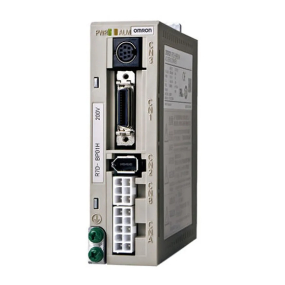
Between power supply/power line terminals and frame ground: 0.5 MΩ min. (at 500 VDC) Dielectric strength Between power supply/power terminals and frame ground: 1,500 VAC for 1 min at 50/60 Hz Between each control signal and frame ground: 500 VAC for 1 min Protective structure Built into panel (IP10). - Page 6 G05030H G020030H G40030H G75030H (R88M-) G10030H GP20030H GP40030H GP10030H Servodrive part names SmartStep2 Servo Drive (100 - 400 W models) Alarm indicator (ALM) Power supply indicator Communications connector (CN3) Control I/O connector (CN1) Encoder input connector (CN2) Motor connector (CNB)
- Page 7 Blank No brake 200 W Brake 400 W 750 W Rated Speed (r/min) Voltage and encoder specifications 3000 H: 230 V with incremental encoder Servo motor / servo drive combination Servo motor Family Voltage Speed Rated torque Capacity Model Cylindric...
-
Page 8: Servo Motor Specifications
3 times each in the X, Y, and Z directions Insulation resistance 20 MΩ min. at 500 VDC between the power terminals and FG terminal Dielectric strength 1,500 VAC (50 or 60 Hz) for 1 minute between the power terminals and FG terminal Run position Any direction Insulation grade... - Page 9 Allowable thrust load Weight Without brake With brake Encoder resolution Phase A and B: 2,500 pulses/rotation, Phase Z: 1 pulse/rotation 130 × 120 × t10 (Al) 170 × 160 × t12 (Al) Radiation shield dimensions 3.0 × 10 9.0 × 10 9.0 ×...
- Page 10 2 x M4 165±1 179±1 190 180 output 2 x 170 mm output connector flexes flexes to servo drive power supply input 1 x 130 mm output flexes Filter model Rated current Leakage current...
-
Page 11: Servo Motors
(Straight shaft with key) Brake connector Encoder connector Servomotor connector M (depth: L) Four, Z dia. C × C Flat type 3000 r/min (230 V, 100 W - 400 W) Dimensions (mm) Without With Flange surface Shaft end Aprox. Mass (Kg) brake... -
Page 12: Installation
Frame ground *1. An External Regeneration Resistor can be connected. Connect this resistor if the regenerative energy exceeds regeneration absorption capacity in the Servo Drive. Note: 1.The dynamic brake operates when the main circuit power supply or the control circuit power supply is turned OFF. - Page 13 Shell *1 B3-B2 are short-circuited. If the internal regenerative resistor is insufficient, remove the wire between B2 and B3 and connect an external regen- erative resistor between B1 and B2. *2 Use only when an absolute encoder. If a backup battery is connected, an encoder cable with a battery is not required.
-
Page 14: Ordering Information
Terminal block General purpose signals Filter (with pulse output) ABCDE Note: The symbols ... show the recommended sequence to select the components in a SmartStep 2 servo system Servo motor Cylindrical servo motors (3,000-r/min) Symbol Specifications Servo motor model Compatible servo drives... - Page 15 CJ1W-NC414 XW2Z-500X 10 m XW2Z-010X Terminal block for external signals ( with M3 screw and for pin terminals) XW2B-20G4 Terminal block ext. signals ( with M3.5 screw and for fork/round terminals) XW2B-20G5 Terminal block ext. signals ( with M3 screw and fork/round pin terminals)
- Page 16 External Regenerative Resistor Connection Cable, 2 meters R7A-CLB002RG Parameter unit & computer software Specifications Model Parameter copy unit (with cable) R88A-PR02G Configuration and monitoring software tool for servo drives and inverters. (CX-drive version 1.8 or higher) CX-drive AC servo systems...
- Page 17 Brake cable Terminal block General purpose signals (with pulse output) ABCDE Note: The symbols ... show the recommended sequence to select the components in a SmartStep 2 servo system. Servo drives Symbol Specifications Servo drive model Compatible rotary servo motors...
- Page 18 Connect to Model Terminal block cable for external signals Position control units (high-speed type) 0.5 m XW2Z-C50X (for input common, forward/reverse run prohibited inputs, CJ1W-NC234 XW2Z-100X emergency stop input, origin proximity input and interrupt CJ1W-NC434 XW2Z-200X input) CJ1W-NC214 XW2Z-300X CJ1W-NC414 XW2Z-500X...
- Page 19 OMRON EUROPE B.V. Wegalaan 67-69, NL-2132 JD, Hoofddorp, The Netherlands. Tel: +31 (0) 23 568 13 00 Fax: +31 (0) 23 568 13 88 www.industrial.omron.eu Austria Germany Portugal Turkey Tel: +43 (0) 2236 377 800 Tel: +49 (0) 2173 680 00...
Need help?
Do you have a question about the SMARTSTEP2 and is the answer not in the manual?
Questions and answers