Sign In
Upload
Manuals
Brands
OMRON Manuals
Amplifier
SMARTSTEP R7M-A Series
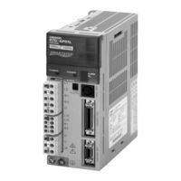
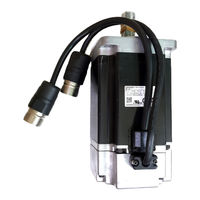
OMRON SMARTSTEP R7M-A Series Manuals
Manuals and User Guides for OMRON SMARTSTEP R7M-A Series. We have
3
OMRON SMARTSTEP R7M-A Series manuals available for free PDF download: User Manual
OMRON SMARTSTEP R7M-A Series User Manual (250 pages)
SMARTSTEP A SERIES Servomotors/Servo Drivers
Brand:
OMRON
| Category:
Amplifier
| Size: 4.29 MB
Table of Contents
General Warnings
7
Installation and Wiring Precautions
8
Storage and Transportation Precautions
8
Operation and Adjustment Precautions
9
Maintenance and Inspection Precautions
10
Warning Labels
11
Table of Contents
17
Chapter 1. Introduction
19
Features
20
Faster Response and Rotation Speed
20
Constant Accuracy
20
Resolution Settings
20
Cylinder-Style and Flat-Style Servomotors
21
A Wider Selection of Programming Devices
21
System Configuration
22
Servo Driver Nomenclature
23
Applicable Standards
24
EC Directives
24
UL and Cul Standards
24
System Block Diagrams
25
200 V Ac: R7D-Apa3H/-Apa5H/-Ap01H/-Ap02H/-Ap04H
26
200 V Ac: R7D-Ap08H
26
Chapter 2. Standard Models and Specifications
27
Standard Models
28
Servomotors
28
Servo Drivers
28
3,000-R/Min Flat-Style Servomotors
28
Reduction Gears (Straight Shaft with Key)
29
Servo Relay Units for CN1
30
Control Cables for CN1
30
Integrated Servomotor Cables
30
Separate Servomotor Cables
30
Peripheral Cable Connectors
31
Parameter Units
31
External Regeneration Resistors
31
DC Reactors
31
External and Mounted Dimensions
32
Single-Phase/Three-Phase 200 V AC: R7D-AP08H (750 W)
34
Wall Mounting
34
Front Panel Mounting (Using Mounting Brackets)
34
Parameter Unit
35
R7A-PR02A Hand-Held Parameter Unit
35
Cylinder-Style Servomotors Without a Brake
36
Cylinder-Style Servomotors with a Brake
36
Flat-Style Servomotors Without a Brake
38
Flat-Style Servomotors with a Brake
38
Reduction Gears
39
Servo Driver Specifications
43
General Specifications
43
Performance Specifications
44
Terminal Block Specifications
45
Control I/O Specifications (CN1)
46
Control I/O and External Signals for Position Control
46
Control I/O Signals
47
CN1 Control Inputs
47
CN1 Control Outputs
47
Interface for RS-422
48
CN1: Pin Arrangement
48
CN1 Connectors (36P)
48
Control Input Circuits
49
Position Command Pulse Inputs and Deviation Counter Reset Inputs
49
Sequence Inputs
49
Control Output Circuits
50
Sequence and Alarm Outputs
50
Phase-Z Output
50
Control Input Details
51
Command Pulse Timing
53
RUN Command Input (14: RUN)
54
Alarm Reset (18: RESET)
54
Control Output Details
54
Control Output Sequence
54
Encoder Input Connector Specifications (CN2)
55
Communications Connector Specifications (CN3)
55
Positioning Completed Output (8: INP)
55
CN3 Connectors Used (8P)
55
Monitor Output Connector Specifications (CN4)
56
CN4 Connectors Used (4P)
56
Servomotor Specifications
57
3,000-R/Min Cylinder-Style Servomotors
58
3,000-R/Min Cylinder-Style Servomotors: Torque and Rotation Speed Characteristics
60
3,000-R/Min Flat-Style Servomotors: Torque and Rotation Speed Characteristics
63
Servomotor and Mechanical System Temperature Characteristics
64
Encoder Specifications
64
Reduction Gear Specifications
65
Reduction Gears for SMARTSTEP A-Series Servomotors (R7G-@)
65
Reduction Gears for Cylinder-Style Servomotors
65
Reduction Gears for Flat-Style Servomotors
67
Cable and Connector Specifications
69
Control Cables
69
General Control Cables (R88A-CPU@@@S)
69
Connection Configuration and External Dimensions
69
Connector Terminal Block Cables (R88A-CTU@@@N)
70
Servomotor Cables
72
Robot Cable Bending Durability
72
Power Cables
72
Encoder Cables
72
Specifications of Integrated Cables
73
Integrated Cables for Servomotors Without Brakes (R7A-CEA@@@S)
73
Specifications of Separate Cables
76
Specifications of Standard Power Cables (R88A-CAWA@@@@)
76
Specifications of Robot Power Cables (R88A-CAWA@@@R)
77
Power Cables for Servomotors Without Brakes
78
Power Cables for Servomotors with Brakes
78
Specifications of Standard Encoder Cables (R7A-CRA@@@C)
78
Specifications of Robot Encoder Cables (R7A-CRA@@@CR)
78
Peripheral Cables and Connector Specifications
80
Analog Monitor Cable (R88A-CMW001S)
80
Computer Monitor Cables (R7A-CCA002P@)
81
Encoder Connector (R7A-CNA0@R)
83
Servo Relay Units and Cable Specifications
84
Xw2B-40J6-2B
85
Xw2B-20J6-3B
86
Xw2B-40J6-4A
88
Xw2B-20J6-8A
89
Xw2B-40J6-9A
90
Terminal Block Connection
93
Servo Phase-B Selectors (Not Used)
95
Wiring to Screwless Clamp Terminal Blocks
95
Inserting a Wire
95
Releasing a Wire
95
Servo Relay Unit Wiring Example
96
Upper Terminal Block Pin Arrangement
96
Recommended Screwdriver
96
Lower Terminal Block Pin Arrangement
97
Cables for Servo Relay Units
98
Servo Driver Cables (XW2Z-@J-B5)
98
Servo Driver Cables (XW2Z-@J-B7)
99
Servo Driver Cables (XW2Z-@@@J-B12)
100
Position Control Unit Cables (XW2Z-@J-A3)
103
Position Control Unit Cables (XW2Z-@J-A4)
104
Position Control Unit Cable (XW2Z-@J-A5)
105
Position Control Unit Cables (XW2Z-@J-A8)
107
Position Control Unit Cables (XW2Z-@J-A9)
108
Position Control Unit Cables (XW2Z-@J-A12)
110
Position Control Unit Cables (XW2Z-@J-A13)
111
Position Control Unit Cables (XW2Z@J-A16)
113
Position Control Unit Cables (XW2Z@J-A17)
115
Position Control Unit Cables (XW2Z-@J-A20)
117
Position Control Unit Cables (XW2Z-@J-A21)
119
Position Control Unit Cable (XW2Z-@J-A22)
121
Position Control Unit Cables (XW2Z-@J-A23)
122
Position Control Unit Cables (XW2Z-@J-A25)
124
CJ1M-CPU Unit Cables (XW2Z-100J-A26)
126
Customizable Counter Unit Cables for Special I/O
128
Customizable Counter Unit Cables for General-Purpose I/O
130
Motion Controller Cables for Special I/O
132
Motion Controller Cable for General-Purpose I/O
134
Communications Cables (XW2Z-@J-C1)
136
Parameter Unit Specifications
137
External Regeneration Resistor Specifications
139
R88A-RR22047S External Regeneration Resistor
139
R88A-PX@ DC Reactors
140
Chapter 3. System Design and Installation
141
Installation Conditions
143
Space Around Drivers
143
Ambient Temperature
143
Operating Environment
144
Impact and Load
144
Keeping Foreign Objects out of Units
144
Connecting to Mechanical Systems
145
Water and Drip Resistance
145
Wiring
148
Connecting Cable
148
Selecting Connecting Cables
149
Servo Relay Unit Cables
149
Selecting Connecting Cables Without Communications Support
149
Selecting Connecting Cables with Communications Support
150
Connector-Terminal Block and Cables
150
General Control Cables and Control I/O Connecto
151
Integrated Cables
151
Separate Cables
151
Computer Monitor Cable
152
Analog Monitor Cable
152
Peripheral Device Connection Examples
153
Three-Phase Input: R7D-AP08H
154
Terminal Block Wiring
155
Terminal Block Names and Functions
155
Terminal Block Wire Sizes
156
200V AC Input (R7D-AP@H)
157
Wire Sizes and Allowable Current
157
600-V Heat-Resistant Vinyl Wiring (HIV) (Reference Values)
157
Terminal Block Wiring Procedure
158
Wiring for Noise Resistance
159
Single-Phase Power Supply Input
159
Three-Phase Power Supply Input (R7D-AP08H)
160
Selecting Components
161
No-Fuse Breakers (NFB)
161
Maximum Input Current
161
Servo Driver Inrush Current
161
Surge Absorbers
162
Noise Filters for Power Supply Input
162
Noise Filters for Servomotor Output
163
Surge Killers
163
Contactors
164
Leakage Breakers
164
Leakage Breaker Connection Example
164
Harmonic Current Countermeasures (DC Reactor)
165
Improving Encoder Cable Noise Resistance
165
Improving Control I/O Signal Noise Resistance
166
Conforming to EMC Directives
166
Wiring Method
167
Control Panel Structure
169
Case Structure
169
Cover Structure
169
Noise Filter for Brake Power Supply
173
Regenerative Energy Absorption
177
Regenerative Energy Calculation
177
Horizontal Axis
177
Vertical Axis
178
Servo Driver Regenerative Energy Absorption Capacity
179
Amount of Internal Regeneration Resistance in Servo Drivers
179
Regenerative Energy Absorption by External Regeneration Resistance
180
Combining External Regeneration Resistors
181
Servo Driver Minimum Connection Resistance and External Regeneration Resistor Combinations
181
Wiring External Regeneration Resistance
182
Chapter 4. Operation
183
Operational Procedure
185
Switch Settings
186
Switch Nomenclature and Functions
186
Unit No. Rotary Switch: UNIT No. (RS-422/485)
186
Gain Adjustment Rotary Switch: GAIN
186
Setting Function Switches
187
Turning Function Switches on and off
187
Switch/Parameter Switch (Switch 6)
187
Resolution Setting (Switches 4 and 5)
187
Dynamic Brake Setting (Switch 2)
188
Online Autotuning Switch
188
Preparing for Operation
189
Turning Power on and Checking Indicators
189
Items to Check before Turning on the Power
189
Checking Power Supply Voltage
189
Turning on Power
190
Checking Displays
190
Trial Operation
191
Preparing for Trial Operation
191
Turning off the Servomotor
191
No-Load Operation
191
Loaded Low-Speed Operation
192
Operation under Actual Conditions
192
Completing the Trial Operation
192
Gain Adjustments
193
Online Autotuning
193
What Is Online Autotuning?
193
Online Autotuning Procedure
194
Setting the Gain Adjustment Rotary Switch During Online Autotuning
195
Manual Tuning
195
Manual Tuning Procedure
196
User Parameters
197
Parameter Tables
197
Parameter Details
199
Setting Explanation
199
Speed Loop Gain
200
Speed Loop Integral Time Constant
200
Position Loop Gain
201
Inertia Ratio
201
Feed-Forward Amount
202
Feed-Forward Command Filter
202
Online Autotuning Setting – Online Autotuning Selection
202
Online Autotuning Function – Adhesive Friction Compensation Selection
203
Position Control Setting 1 –- Command Pulse Mode (Position)
203
Position Control Setting 1 – Deviation Counter Reset
204
Position Control Setting 1 –Deviation Counter Reset for Servo off and Alarms
204
Electronic Gear Ratio G1 (Numerator)
204
Electronic Gear Ratio G2 (Denominator)
204
Position Command Filter Time Constant 1 (Primary Filter)
205
Position Control Setting 2 – Position Command Filter Selection
205
Position Command Filter Time Constant 2 (Trapezoidal Acceleration and Deceleration)
205
Jog Speed
205
Torque Command Filter Time Constant
206
Forward Torque Limit
206
Reverse Torque Limit
206
Positioning Completed Range
206
Regeneration Resistor Capacity
207
Operating Functions
208
Position Control
208
Using Function Switches (Function Switch 6 Turned OFF)
208
Using Parameters (Function Switch 6 Turned ON)
208
Brake Interlock
209
Precautions for Using Electromagnetic Brake
209
RUN Timing (Servomotor Stopped)
209
Power Supply Timing (Servomotor Stopped)
209
RUN, Error, and Power Supply Timing (Servomotor Rotating)
210
Power Supply Timing (Servomotor Rotating)
210
Torque Limiting
211
Electronic Gear Function
211
Limiting the Steady Force Applied During Normal Operation
211
Parameters Requiring Settings
212
Position Command Filter Function
213
Primary Filter
213
Linear Acceleration and Deceleration
214
Chapter 5. Troubleshooting
215
Measures When Trouble Occurs
216
Preventive Checks before Trouble Occurs
216
Check the Power Supply Voltage
216
Selecting Analysis Tools
216
Precautions
217
Computer Monitor Software
217
Replacing the Servomotor and Servo Driver
218
Replacing the Servomotor
218
Replacing the Servo Driver
218
Alarms
219
Servo Driver Alarm Display
219
Alarm Table
220
Error Diagnosis Using Alarm Display
221
Troubleshooting
221
Troubleshooting by Means of Operating Status
226
Overload Characteristics (Electron Thermal Characteristics)
229
Periodic Maintenance
230
Chapter 6. Appendix
233
Connection Examples
234
Connecting to SYSMAC CS1W-NC133/233/433
235
Connecting to SYSMAC CJ1W-NC113/213/413
236
Connecting to SYSMAC CJ1W-NC133/233/433
237
Connecting to SYSMAC CS1W-HCP22
238
Connecting to 3F88M-DRT141 Single-Axis Positioner for Devicenet
239
Connecting to SYSMAC C200H-NC112
240
Connecting to SYSMAC C500-NC113/211 or C200H-NC211
241
Connecting to Oriental XG8200S
242
Connecting to Oriental SG8030J
243
Connecting to Keyence HC-50
244
Connecting to Melec C-870V1
245
Connecting to SYSMAC CQM1H-PLB21
246
Connecting to SYSMAC CPM2C
247
Revision History
249
Advertisement
Omron SMARTSTEP R7M-A Series User Manual (251 pages)
Servomotors/Servo Drivers
Brand:
Omron
| Category:
Servo Drives
| Size: 3.51 MB
Table of Contents
Table of Contents
17
Chapter 1. Introduction
19
Features
20
System Configuration
22
Servo Driver Nomenclature
23
Applicable Standards
24
System Block Diagrams
25
Chapter 2. Standard Models and Specifications
27
Standard Models
28
External and Mounted Dimensions
32
Servo Driver Specifications
43
Servomotor Specifications
57
Reduction Gear Specifications
65
Cable and Connector Specifications
69
Omron SMARTSTEP R7M-A Series User Manual (250 pages)
Servomotors/Servo Drivers
Brand:
Omron
| Category:
Servo Drives
| Size: 3.45 MB
Table of Contents
Table of Contents
18
Chapter 1. Introduction
20
Features
21
System Configuration
23
Servo Driver Nomenclature
24
Applicable Standards
25
System Block Diagrams
26
Chapter 2. Standard Models and Specifications
28
Standard Models
29
External and Mounted Dimensions
33
Servo Driver Specifications
44
Servomotor Specifications
58
Reduction Gear Specifications
66
Cable and Connector Specifications
70
Advertisement
Advertisement
Related Products
OMRON SMARTSTEP Junior R7D-ZP
OMRON SMARTSTEP Junior R7M-Z
OMRON SMARTSTEP R7D-AP Series
Omron R7
Omron SmartStep R7D-AP02H
Omron SmartStep R7D-AP08H
Omron R7D-YV2
Omron SMARTSTEP R7A-PR02A
Omron SMARTSTEP R7D-BPA5L
Omron SMARTSTEP R7D-AP02L
OMRON Categories
Blood Pressure Monitor
Controller
Accessories
Switch
Inverter
More OMRON Manuals
Login
Sign In
OR
Sign in with Facebook
Sign in with Google
Upload manual
Upload from disk
Upload from URL