Omron E3X-NA Series Manual
User-friendly fiber-optic amplifier
Hide thumbs
Also See for E3X-NA Series:
- Manual (29 pages) ,
- Datasheet (12 pages) ,
- Instruction manual (44 pages)
Advertisement
Quick Links
User-Friendly Fiber-Optic Amplifier
Solve Your Basic Sensing Challenges
Easily with the E3X-NA Series
I
Streamlined features provide basic sensing
immediately after plug-in
I
Wire-saving amplifiers reduce installation
time and minimize space requirements
I
Master/slave connector design affords
connectivity for up to 16 wire-saving
amplifiers
I
Use the LED bar display to quickly confirm
sensor performance
I
Optical communication design prevents
mutual interference for up to 5 amplifiers
I
Green LED models address mark-detecting
applications
I
High-speed models have a response time
of 50 µs
I
Select a water-resistant model (IP66 rating)
using an M8 connector
I
Prewired water-resistant models are available
Ordering Information:
Amplifier Units, Connectors, Accessories and Fiber-Optics
Amplifier Units with Cables
I
Type
Standard
High-speed
Mark-detection
Water-resistant
Downloaded from
Elcodis.com
electronic components distributor
Part number
NPN output
PNP output
E3X-NA11
E3X-NA41
E3X-NA11F
E3X-NA41F
E3X-NAG11
E3X-NAG41
E3X-NA11V
E3X-NA41V
Control output
Appearance
ON/OFF
E3X-NA
Advertisement

Related Manuals for Omron E3X-NA Series


Summary of Contents for Omron E3X-NA Series
- Page 1 User-Friendly Fiber-Optic Amplifier E3X-NA Solve Your Basic Sensing Challenges Easily with the E3X-NA Series Streamlined features provide basic sensing immediately after plug-in Wire-saving amplifiers reduce installation time and minimize space requirements Master/slave connector design affords connectivity for up to 16 wire-saving...
- Page 2 XS3F-M422-405-A Accessories (Order Separately) Fiber-Optic Cables Mounting Brackets The E3X-NA amplifiers use Omron’s E32-series fiber-optic cables. With a choice of over 80 sensing heads, you are sure to find one that matches your application requirements. Refer to the Appearance Applicable...
-
Page 3: Specifications
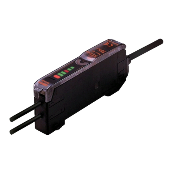
E3X-NA E3X-NA Specifications Amplifier Units Ratings/Characteristics Item Amplifier Units with Cables Connector-ready amplifier units Standard models High-speed Mark-detecting Water-resistant Wire-saving Water-resistant detection models models models models (use M8 models connectors) Output type NPN output E3X-NA11 E3X-NA11F E3X-NAG11 E3X-NA11V E3X-NA6 E3X-NA14V PNP output E3X-NA41 E3X-NA41F... - Page 4 E3X-NA E3X-NA Nomenclature Amplifier Units Sensitivity Indicator 8-Turn Sensitivity Adjuster Operation Mode Selector Use to switch between Lock Button Incident level Indicators Light ON and Dark ON modes. Operation Indicator Timer Switch ON: Timer function is ON. OFF: Timer function is OFF. LED Bar Display Indicators In addition to an operation indicator (orange), the E3X-NA also has...
-
Page 5: Operation
E3X-NA E3X-NA Operation Output Circuits Output Model Mode Timing chart State of Output circuit selector output transistor E3X-NA11 LIGHT Light ON Incident light Brown E3X-NA6 No incident light Operation E3X-NAG11 (L/ON) Operation indicator indicator E3X-NA11F (orange) (orange) Load E3X-NA11V Photo- Photo- electric electric... - Page 6 E3X-NA E3X-NA Engineering Data (Typical) Parallel Operating Range At max. sensitivity. (Use for optical axis adjustment at installation.) E32-T11R E32-TC200 E32-T11L/T12L E3X-NAG@ E3X-NAG@ E3X-NAG@ 0.5 0.6 −50 Distance X (m) Distance X (m) Distance X (m) −100 −100 −100 E3X-NA@F −200 −200 −150...
- Page 7 E3X-NA E3X-NA Number of Turns of Sensitivity Adjuster vs. Sensing Distance E32-T11L E32-D11L E3X-NA@ (V) E3X-NA@ (V) E3X-NA@F Number of turn Number of turns Number of t Sensing Distance vs. Hysteresis E32-T11L E32-D11L E3X-NA@ (V) E3X-NA@ (V) 600 700 Distance (mm) Distance (mm Distance (mm) Distance...
- Page 8 E3X-NA E3X-NA Dimensions Unit: mm (inch) Amplifier Units Amplifier Units with Cables (with Mounting Bracket Attached) Incident level indicators A (See note 1.) E3X-NA11 Operation indicator Cable (See note 2.) E3X-NA11F E3X-NA41 E3X-NA41F 13.05 E3X-NAG11 15.75 E3X-NAG41 64.3 (2.53) 38.6 Two, 2.4 dia.
- Page 9 E3X-NA E3X-NA Wire-Saving Amplifiers Incident level indicators E3X-NA6 Operation indicator E3X-NA8 13.05 15.75 (0.39) Two, 64.3 (2.53) 2.4 dia. 31.5 (1.24) 10.7 38.6 36.7 Hole for optical communications (for preventing mutual interference) Dimensions with Slave Connector Connected Dimensions with Master Connector Connected 71 (2.80) 71 (2.80) 67.5...
- Page 10 E3X-NA E3X-NA Amplifier Unit Connectors (Order Separately) Master Connectors E3X-CN11 2 m (6.56 ft.) 10.7 See note. 4 dia. 14.4 30± 10± 15.1 Note: A 4-dia., 3-conductor, vinyl-insulated round cable (conductor cross-sectional area: 0.2 mm ; insulation diameter: 1.1 mm) is used. Slave Connectors E3X-CN12 2 m (6.56 ft.)
- Page 11 E3X-NA E3X-NA Accessories (Order Separately) Mounting Bracket for E3X-NA , E3X-NA F, and E3X-NAG Models E39-L143 34.8 (1.37) 10.3 Mounting Holes Two, M3 26.8 Two, 3.2 dia. 16± Material: Stainless steel (SUS 304) Four, R1.7 10.3 10 max. Mounting Bracket for E3X-NA V Models E39-L148 R1.7...
- Page 12 E3X-NA E3X-NA Precautions Wiring Precautions Wiring the Amplifier Unit Read the following before using the Amplifier Unit and Sensor to Cable ensure safety. The cable can be extended, provided that the extension wire Power Supply Voltage applied is at least 0.3 mm thick and the total distance no more than 100 m.
- Page 13 E3X-NA E3X-NA Mounting the Amplifier Unit Removal Pull the lock tab of the Amplifier Unit with a flat blade screwdriver Joining Amplifier Units in direction (3) and lift the fiber insertion part in direction (4) as Mount the Amplifier Units one at a time onto the DIN rail. shown below.
- Page 14 E3X-NA E3X-NA Mounting the Fiber Unit Tightening Force The tightening force applied to the Fiber Unit should be as shown below. Protective cover Screw-Mounting Model Cylindrical Model Unlocked Locked Retaining screw (flat head or sunken head) Spring mounting clip (M3 max.) Toothed washers Note: To maintain the fiber properties, confirm that the lock is re-...
- Page 15 E3X-NA E3X-NA Mounting Amplifier Units with Connection Connectors Do not pull or press the Fiber Units. The Fiber Units have a with- stand force of 9.8 N or 29.4 N maximum (pay utmost attention Mounting Connectors because the fibers are thin). 1.
- Page 16 E3X-NA E3X-NA Mounting End Plate (PFP-M) Reflector Use of E39-R3 Reflector Depending on how it is mounted, an Amplifier Unit may move during operation. In this case, use an End Plate. Use detergent, etc., to remove any dust or oil from the surfaces Before mounting an End Plate, remove the clip from the master where tape is applied.
- Page 17 E3X-NA E3X-NA Sensing Distance with Fiber Optic Cables Through-beam Fiber Units Refer to the end of the following table for notes and precautions. Indicates models that allow free cutting. Models without this mark do not allow free cutting. Free-cut : Red light : Green light Application Features...
- Page 18 E3X-NA E3X-NA Application Features Appearance Applicable Sensing distance (mm) Standard object Part Permissible (see notes) Amplifier Unit (Values in parentheses: when number bending (min. sensing using the E39-F1 Lens Unit) radius target: opaque) Flexible Ideal for E3X-NA@ (V) 1.0-mm dia. 4 mm E32-T11 Free-cut...
- Page 19 E3X-NA E3X-NA Application Features Appearance Applicable Sensing distance (mm) Standard object Part Permissible (see notes) Amplifier Unit (Values in parentheses: when number bending (min. sensing using the E39-F1 Lens Unit) radius target: opaque) Chemical- Teflon-cov- E3X-NA@ (V) 4.0-mm dia. 40 mm E32-T12F Free-cut resistant...
- Page 20 E3X-NA E3X-NA Application Features Appearance Applicable Sensing distance (mm) Standard object Part Permissible (see notes) Amplifier Unit (Values in parentheses: when number bending (min. sensing using the E39-F1 Lens Unit) radius target: opaque) Area sensing Multi-point detection E3X-NA@ (V) 2.0-mm dia. E32-M21 25 mm (0.03-mm dia.)
- Page 21 E3X-NA E3X-NA Fiber Units with Reflective Sensors Refer to the end of the following table for notes and precautions. Indicates models that allow free cutting. Models without this mark do not allow free cutting. Free-cut : Red light : Green light Application Features Appearance...
- Page 22 E3X-NA E3X-NA Application Features Appearance Applicable Sensing distance (mm) *1 Standard object Part Permis- (see note) (min. Amplifier Unit number sible sensing target: bending Gold wire) radius Flexible Ideal for mounting on E3X-NA@ (V) 150×150 4 mm E32-D11 moving sections (0.01-mm dia.) E3X-NAG@ 25×25...
- Page 23 E3X-NA E3X-NA Application Features Appearance Applicable Sensing distance (mm) *1 Standard object Part Permis- (see note) (min. Amplifier Unit number sible sensing target: bending Gold wire) radius Coaxial M6coaxial; E3X-NA@ (V) 200×200 25 mm Free-cut E32-CC200 high- (0.01-mm dia.) precision E3X-NAG@ 50×50 positioning...
- Page 24 E3X-NA E3X-NA Application Features Appearance Applicable Sensing distance (mm) *1 Standard object Part Permis- (see note) (min. Amplifier Unit number sible sensing target: bending Gold wire) radius Heat- E3X-NA@ (V) 150×150 35 mm Resists 150°C Free-cut E32-D51 resistant *2; fiber (0.03-mm dia.) sheath materi- M6 screw...
- Page 25 E3X-NA E3X-NA Downloaded from Elcodis.com electronic components distributor...
- Page 26 E3X-NA E3X-NA Downloaded from Elcodis.com electronic components distributor...
- Page 27 E3X-NA E3X-NA Downloaded from Elcodis.com electronic components distributor...
- Page 28 E3X-NA E3X-NA ALL DIMENSIONS SHOWN ARE IN MILLIMETERS. To convert millimeters into inches, multiply by 0.03937. To convert grams into ounces, multiply by 0.03527. OMRON ELECTRONICS LLC OMRON ON-LINE OMRON CANADA, INC. One East Commerce Drive 885 Milner Avenue Global - http://www.omron.com...
Need help?
Do you have a question about the E3X-NA Series and is the answer not in the manual?
Questions and answers