
Related Manuals for Omron V640-HAM11-ETN


Summary of Contents for Omron V640-HAM11-ETN
- Page 1 CIDRW SYSTEM V640 SERIES USER'S MANUAL AMPLIFIER UNITS V640-HAM11-ETN V640-HAM11-L-ETN CIDRW HEADS V640-HS61 V640-HS62 Cat. No. Z308-E1-02...
- Page 2 Introduction Thank you for purchasing the V640-series CIDRW System. Please observe the following points when operating the V640-series CIDRW System: • Allow the CIDRW System to be installed and operated only by qualified specialist with a sufficient knowledge of electrical systems. •...
-
Page 3: Cidrw System
SECTION 2 SECTION 3 Preparing for Communications Reading from/Writing to ID Tags SECTION 4 SECTION 5 Browser Interface Troubleshooting SECTION 6 SECTION 7 Appendix CIDRW System V640-HAM11-ETN Amplifier Unit V640-HAM11-L-ETN Amplifier Unit V640-HS61 CIDRW Head V640-HS62 CIDRW Head User's Manual... - Page 4 PROFITS OR COMMERCIAL LOSS IN ANY WAY CONNECTED WITH THE PRODUCTS, WHETHER SUCH CLAIM IS BASED ON CONTRACT, WARRANTY, NEGLIGENCE, OR STRICT LIABILITY. In no event shall responsibility of OMRON for any act exceed the individual price of the product on which liability is asserted.
-
Page 5: Performance Data
Performance data given in this document is provided as a guide for the user in determining suitability and does not constitute a warranty. It may represent the result of OMRON’s test conditions, and the users must correlate it to actual application requirements. -
Page 6: Applicable Standards
INTRODUCTION Applicable Standards The CIDRW System complies with the following international regulations and standards. 1. USA Amplifier Unit CIDRW Head FCC Part 15 Subpart C V640-HAM11-ETN V640-HS61 FCC ID: E4EV640HAM11 FCC Part 15 Subpart C V640-HAM11-L-ETN V640-HS62 FCC ID: E4EV640HAM11L FCC NOTICE This device complies with part 15 of the FCC Rules. - Page 7 V640-HAM11-L-ETN ΣΥΜΜΟΡΦΩΝΕΤΑΙ ΠΡΟΣ ΤΙΣ ΟΥΣΙΩΔΕΙΣ ΑΠΑΙΤΗΣΕΙΣ ΚΑΙ ΤΙΣ ΛΟΙΠΕΣ ΣΧΕΤΙΚΕΣ ΔΙΑΤΑΞΕΙΣ ΤΗΣ ΟΔΗΓΙΑΣ 1999/5/ΕΚ Con la presente Omron dichiara che questo V640-HAM11-ETN / V640-HAM11-L-ETN é conforme ai requisiti essenziali ed alle altre dispo- Italian sizioni pertinenti stabilite dalla direttiva 1999/5/CE.
- Page 8 INTRODUCTION 4. China Amplifier Unit CIDRW Head CMIIT ID: 2010DJ5964 V640-HAM11-ETN V640-HS61 CMIIT ID: 2010DJ5965 V640-HAM11-L-ETN V640-HS62 5. Korea Amplifier Unit CIDRW Head OMR-V640-HAM11-ETN V640-HAM11-ETN V640-HS61 OMR-V640-HAM11-L-E V640-HAM11-L-ETN V640-HS62 6. Taiwan Amplifier Unit CIDRW Head CCAB10LP461AT0 V640-HAM11-ETN V640-HS61 CCAB10LP462AT3 V640-HAM11-L-ETN V640-HS62 7.
-
Page 9: Safety Precautions
INTRODUCTION Safety Precautions ● Definition of Precautionary Information The following notation and alert symbols are used in this User's Manual to provide precautions required to ensure safe usage of a V640-series CIDRW System. The safety precautions that are provided are extremely important to safety. -
Page 10: Precautions For Safe Use
INTRODUCTION Precautions for Safe Use Please observe the following precautions for safe use of the products. • Never use the product in an environment where combustible or explosivegas is present. • Please separate from a high-pressure equipment and the power equipment to secure the safety of the operation and maintenance. -
Page 11: Precautions For Correct Use
INTRODUCTION Precautions for Correct Use Please observe the following precautions to prevent failure to operate, malfunctions, or undesirable effects on product performance. ■ About installation Site Do not install this product in the locations subject to the following conditions. • Place where direct sunshine strikes. •... - Page 12 INTRODUCTION ■ About mounting • This product communicates with ID Tags using the 134 kHZ frequency band. Some transceivers, motors, monitoring equipment, and power supplies (power supply ICs) generate electrical waves (noise) that interfere with communications with ID Tags, If you are using the product in the vicinity of any of these devices, check the effect on communications in advance.
- Page 13 INTRODUCTION Reading this Manual Visual Aids Indicates an explanation of a point that must be observed to ensure that the product is capable of its proper functions and perfor- mance. Read this information carefully and follow the cautions. If the product is used incorrectly, data or the equipment itself could be destroyed.
- Page 14 INTRODUCTION MEMO CIDRW System User’s Manual...
- Page 15 INTRODUCTION Table of Contents Table of Contents Introduction Applicable Standards Applicable SEMI Standards Safety Precautions Precautions for Safe Use Precautions for Correct Use Reading this Manual Table of Contents SECTION 1 Product Outline What Is a CIDRW System Features System Configuration Component Names and Functions Flowchart for Getting Started SECTION 2 Installation and Connections/Wiring...
-
Page 16: Table Of Contents
INTRODUCTION Table of Contents SECTION 6 Troubleshooting Troubleshooting SECTION 7 Appendix Specifications and Dimensions Connection Examples Characteristic Data According to Conditions of Use ID Tag Memory Maps Regular Inspection ASCII Code Table Protective Construction SECTION 8 Revision History CIDRW System User’s Manual... - Page 17 SECTION 1 Product Outline What Is a CIDRW System Features System Configuration Component Names and Functions Flowchart for Getting Started CIDRW System User’s Manual...
-
Page 18: What Is A Cidrw System
ID Tag (holder is separate) CIDRW Head Reading and writing information • Model information • Process instruction information • Completion information • Lot information Amplifier Unit • Inspection results Etc. Ethernet hub Recommended: W4S1-05B (OMRON) Host CIDRW System User’s Manual... -
Page 19: Features
Product Outline Features A V640-series CIDRW Head can be connected to a V640-HAM11-ETN or V640-HAM11-L-ETN Amplifier Unit to read and write ID Tags manufactured by Texas Instruments (TI). Reading and writing is performed according to commands from the host device. -
Page 20: System Configuration
SECTION 1 Product Outline System Configuration V640-HAM11-ETN Ethernet hub Host device Recommended: W4S1-05B(OMRON) CIDRW Head Amplifier Unit V640-HS61 V640-HAM11-ETN LAN cable LAN cable V640-HAM11-L-ETN Ethernet hub Host device Recommended: W4S1-05B(OMRON) Amplifier Unit CIDRW Head V640-HAM11-L-ETN V640-HS62 LAN cable LAN cable If the IP address is set on the DIP switch, it will be in the form 192.168.1.@@@. -
Page 21: Component Names And Functions
Turns ON when an error occurs during communications with the host device, or during communications with an ID Tag. CIDRW Head connection port A CIDRW Head is connected here. The V640-HS61 CIDRW Head is used with the V640-HAM11-ETN. The V640-HS62 CIDRW Head is used with the V640-HAM11-L-ETN. Setting DIP switches Set the IP address and enable/disable the Test Mode with this DIP switch. - Page 22 Communications with ID Tags are automatically performed every second and the communications results are displayed on the OPERATING indicator. Refer to page 34. Refer to V640-HAM11-ETN and V640-HAM11-L-ETN Amplifier Units for information on the OPERATING indicator for communi- cations results. Refer to page 19.
- Page 23 SECTION 1 Product Outline V640-HS61 and V640-HS62 CIDRW Heads ■ V640-HS61 Name Function Antenna Used to communicate with ID Tags. Antenna center This is the center of the communications area. Connector Connect to an Amplifier Unit. ■ V640-HS62 V640-HS62 CIDRW HEAD MADE IN JAPAN Name Function...
-
Page 24: Flowchart For Getting Started
SECTION 1 Product Outline Flowchart for Getting Started Installation Refer to page 26. Connection and Wiring Refer to page 29. Setting the Communications Conditions for Amplifier Units Refer to page 34. Test for Communications with the Host Device Refer to page 35. ID Tag <->... - Page 25 SECTION 1 Product Outline Communications Test with Actual Commands Refer to page 38. When you Encounter a Problem... Troubleshooting Refer to page 72. List of Error Messages Refer to page 72. Amplifier Unit Indicators Refer to page 73. Operation Check Flowchart CIDRW System User’s Manual...
- Page 26 SECTION 1 Product Outline MEMO CIDRW System User’s Manual...
- Page 27 SECTION 2 Installation and Connections/Wiring Installation Amplifier Unit CIDRW Head Connections and Wiring Amplifier Unit CIDRW System User’s Manual...
-
Page 28: Installation
SECTION 2 Installation and Connections/Wiring Installation Amplifier Unit Use spring washers and flat washers with the four M4 screws when mounting the Amplifier Unit. Mounting dimensions (Unit: mm) 175±0.5 4-M4 Tighten the M4 screws with a torque not exceeding 1.2 N·m. CIDRW System User’s Manual... -
Page 29: Cidrw Head
SECTION 2 Installation and Connections/Wiring CIDRW Head The area for communications with ID Tags varies substantially according to the installation orientations and the background conditions (metals, noise, etc.). Check the communications area before deciding the installation position. For details on actual communications distances, see Characteristic Data depending on Conditions of Use in Appendix. -
Page 30: Influence Of Background Metal On Id Tag
SECTION 2 Installation and Connections/Wiring ■ Influence of Background Metal on ID Tag Metals in the vicinity of the communications area will affect the range, making it smaller. Refer to page 110. ■ Influence of Noise This CIDRW system uses a frequency of 134 kHz for communications with ID Tags. Equipment such as switching power supplies, inverters, servomotors, or monitors in the surrounding area will adversely affect communications, restricting the communications area. -
Page 31: Connections And Wiring
SECTION 2 Installation and Connections/Wiring Connections and Wiring Amplifier Unit ■ Connector for Connecting a CIDRW Head Align the pin on the connector with the channel in the cable connector and insert the cable connector. Hold the fixed part of the connector while making this insertion. - Page 32 5110:1996) To prevent faulty connections for connectors, the jack on the Amplifier Unit is designed so that non-standard plugs cannot be connected. If a commercially available plug cannot be connected, it may be non-standard. If you use a Hub in your network, please choose a Switching-type Hub (Recommended: W4S1-05B(OMRON)). CIDRW System...
-
Page 33: Power Supply
Recommended Product Manufacturer Model Output current Input voltage OMRON S8VS-01524 24 VDC, 650 mA 100 to 240 VAC *The maximum power consumption of the Amplifier Unit is 150 mA at 24 VDC(V640-HAM11-V3), 400 mA at 24 VDC(V640-HAM11-L). The inrush current, however, must be considered when selecting the power supply capacity. - Page 34 SECTION 2 Installation and Connections/Wiring MEMO CIDRW System User’s Manual...
- Page 35 SECTION 3 Preparing for Communications Setting the Communications Conditions for Amplifier Units Communications Test CIDRW System User’s Manual...
- Page 36 SECTION 3 Preparing for Communications Setting the Communications Conditions for Amplifier Units Set the communications conditions using the DIP switches on the side face of the Amplifier Unit. After changing the DIP switch settings, restart the system. The new settings will not become effective until the system is restarted.
-
Page 37: Cidrw System
SECTION 3 Preparing for Communications Communications Test Communications Test with the Host Device A communications test is performed to confirm that the host device and Amplifier Unit are connected correctly. Refer to Host Communications Specifications. Refer to page 81. Amplifier Unit Host A test is preformed for the Amplifier Unit using the data 12345678. - Page 38 SECTION 3 Preparing for Communications Communications Test between ID Tags and CIDRW System Send a command from the host device and check that normal communications with the ID Tag is pos- sible. Place an ID Tag in the communications area of the CIDRW Head connected to the Amplifier Unit for which communications is to be tested.
- Page 39 SECTION 4 Reading from/Writing to ID Tags Command/Response Format READ WRITE SAME WRITE BYTE WRITE TEST GET PARAMETER GET LAST COMMAND GET COMMUNICATIONS HISTORY CLEAR COMMUNICATIONS HISTORY NOISE MEASUREMENT RESET SET WEB PASSWORD SET NETWORK CIDRW System User’s Manual...
-
Page 40: Command/Response Format
SECTION 4 Reading from/Writing to ID Tags Command/Response Format Command Parameter Command code ⋅ ⋅ ⋅ Response Parameter Response code ⋅ ⋅ ⋅ Command Command Code List Name Value Function READ 0100 When this command is received, the system communicates with the ID Tag, and p.39 reads the specified page(s) of data. -
Page 41: Read
SECTION 4 Reading from/Writing to ID Tags Response Code List Response Type Name Description code Normal end Normal end Command execution is completed normally. Host commu- Format error There is a mistake in the command format. (For example, the command nications error code is undefined, or the page or address specification is inappropriate.) Communica-... -
Page 42: Write
SECTION 4 Reading from/Writing to ID Tags Example: Reading Data from Pages 1 and 3 of the Amplifier Unit. Data Content of the ID Tag Page 1 Page 2 Page 3 Page 4 Command Command code Page designation Binary notation Response Response Page 1... - Page 43 SECTION 4 Reading from/Writing to ID Tags Parameter Description Parameter Description Page designation Pages are specified by setting the bits corresponding to pages that are to be read to 1 and setting the other bits to 0, then converting the result to a hexadecimal character string. Write data The data to be written to the specified pages is specified in ascending order of page numbers.
-
Page 44: Same Write
SECTION 4 Reading from/Writing to ID Tags ■ SAME WRITE This command writes the same data to multiple pages of an ID Tag. Any page(s) can be specified. Command Write data Command code Page designation (8 characters) ⋅ ⋅ ⋅ Data 1 Data 8 Page... -
Page 45: Byte Write
SECTION 4 Reading from/Writing to ID Tags ■ BYTE WRITE This command writes data to any specified number of bytes starting from the address specified in the ID Tag. The maximum number of bytes that can be written at one time is 128. Command Write data First... -
Page 46: Test
SECTION 4 Reading from/Writing to ID Tags ■ TEST Performs a communications test on communications between the host device and Amplifier Unit. When an Amplifier Unit receives a test command, it sends the response code and command test data to the host device as the response. Command Test data Command code... -
Page 47: Nak
SECTION 4 Reading from/Writing to ID Tags ■ NAK Sends the response made immediately before again. Command Command code Response Sends the response made immediately before again. A response will not be returned if a NAK command is executed immediately after startup. ■... - Page 48 SECTION 4 Reading from/Writing to ID Tags Example 1: Getting the Model Number of Amplifier Unit Command Parameter Command code type Response The product model number is returned as an ASCII text string. Response Model number code Example 2: Getting the Firmware Version of Amplifier Unit Command Parameter Command code...
- Page 49 SECTION 4 Reading from/Writing to ID Tags Response The response code (00: normal) and MAC address are returned. Response code MAC address * The above response is for a MAC address of 00:1F:16:1A:B9:8E. Example 4: Checking If Network Settings on DIP Switch on Amplifier Unit Are Enabled or Disabled Command Parameter Command code...
- Page 50 SECTION 4 Reading from/Writing to ID Tags Example 6: Checking the Subnet Mask on the DIP Switch of Amplifier Unit Command Parameter Command code type Response The response code (00: normal) and subnet mask (decimal, four octets of 3 digits each) are returned. Response code Subnet mask on DIP switch Second octet...
- Page 51 SECTION 4 Reading from/Writing to ID Tags Example 9: Getting the Memory Status of Amplifier Unit Command Parameter Command code type Response The response code (00: normal) and memory check results for internal EEPROM are returned. Response Memory status code * “Memory status”...
-
Page 52: Get Last Command
SECTION 4 Reading from/Writing to ID Tags ■ GET LAST COMMAND Gets the command code of the last command that was executed. Command Command code Response This command returns the command code of the last command that was executed. When There Is a Previously Executed Command Response Command code code... -
Page 53: Clear Communications History
SECTION 4 Reading from/Writing to ID Tags Example 1: Getting the Communications History of Amplifier Unit Command Command code Response The following response is returned if there are 32,000 total communications, 30,000 successful communications, and 2,000 failed communications. Total number of suc- Response Total number of com- Total number of failed... -
Page 54: Reset
SECTION 4 Reading from/Writing to ID Tags ■ RESET All Amplifier Unit processing is stopped, and the initial status is re-established. Command Command code Response There is no response to this command. ■ SET WEB PASSWORD This command sets the Web password. If you set a password, a Password entry window will be displayed when you start the browser window. -
Page 55: Set Network
SECTION 4 Reading from/Writing to ID Tags ■ SET NETWORK This command sets the IP address and subnet mask in ROM. Command Command code First octet Second octet Third octet Fourth octet Parameter Description Parameter Description Type IP address setting: 00 Subnet mask setting: 01 First to fourth octets The address is set in decimal in four octets of three characters each. - Page 56 SECTION 4 Reading from/Writing to ID Tags MEMO CIDRW System User’s Manual...
- Page 57 SECTION 5 Browser Interface Browser Operation Windows Window Configuration CIDRW System User’s Manual...
- Page 58 SECTION 5 Browser Interface Browser Operation Windows To operate an Amplifier Unit from a browser, connect the Ethernet cables, start a browser on the computer, and specify the IP address of the Amplifier Unit as the URL. The Browser Window will be displayed. The Status Window will be displayed first.
- Page 59 SECTION 5 Browser Interface Window Configuration IP address of Amplifier Unit Language Buttons Menu Buttons Main Display CIDRW System User’s Manual...
- Page 60 SECTION 5 Browser Interface Password Entry Window If a Web password is set in the Amplifier Unit, the Password Entry Window will be displayed before the Browser Window is displayed. Enter the password and click the OK Button in this window. If the pass- word is correct, the Status Window will be displayed.
- Page 61 SECTION 5 Browser Interface If the password is not correct, the following window will be displayed. Click the Retry Button. The Password Entry Window will be displayed again. CIDRW System User’s Manual...
- Page 62 SECTION 5 Browser Interface Status Window The Status Window displays the model number, firmware version, MAC address, and other information on the Amplifier Unit so that you can check it. Click the Refresh Button at the top of the window to update the displayed information (latest communication, communication history, and H/W status).
- Page 63 SECTION 5 Browser Interface A Amplifier Unit Information Item Description Comments Model The product model number is displayed. Firmware Version The firmware version is displayed. MAC Address The MAC address is displayed. DIP-SW "Enabled" is displayed if the Amplifier Unit is set to use the IP address that is set on the DIP switch.
- Page 64 SECTION 5 Browser Interface Setting Window The network settings (IP address and subnet mask) of the Amplifier Unit and the Web password can be set in the Setting Window. The values that are set are enabled when the Amplifier Unit is restarted. If the Save Button is clicked when the password box is empty, the Web password will be cleared.
- Page 65 SECTION 5 Browser Interface Command Window The Command Window can be used to communicate with ID Tags. The Command Window has two tab pages: "CID R/W" and "V640 Command." V640 Command CID R/W CIDRW System User’s Manual...
- Page 66 SECTION 5 Browser Interface CID R/W Tab Page The CID R/W Tab Page allows you to read or write ID Tag data by specifying the offset, length, and maximum bytes of CID. If writing is executed, you must also specify the write data. CID Read Button CID Write Button Select this check box to...
- Page 67 SECTION 5 Browser Interface Item Description Comments Offset Specify the CID offset between 0 and 15 bytes. Length Specify the CID length between 1 and 16 bytes. Maximum byte of CID Specify the maximum CID length between 1 and 16 bytes. Write Data For the write data, specify only the number of bytes for the specified Specify only visible ASCII...
- Page 68 SECTION 5 Browser Interface V640 Command Tab Page The V640 Command Tab Page allows you to read and write data according to the command format of the Amplifier Unit OK/NG Display Area Page/Write Designation Area Page Designation Area Send Button Write Data Designation Area Select this check box to repeat the command.
- Page 69 SECTION 5 Browser Interface ■ Page/Write Designation Area Select Read or Write in the Page/Write Designation Area. ■ OK/NG Display Area The command execution results will be displayed as "OK" or "NG" in the OK/NG Display Area. If "NG" is displayed, information on the error will be displayed. •...
- Page 70 SECTION 5 Browser Interface ■ Page Designation Area Select the check boxes to specify the pages to be read or written. ■ Write Data Designation Area When writing data, specify the data to write to the ID Tag as a hexadecimal string. Specify 16 charac- ters for each page that you specify in the Page Designation Area.
- Page 71 SECTION 5 Browser Interface Noise Measurement Window The Noise Measurement Window allows you to continuously send the NOISE MEASUREMENT com- mand to the Amplifier Unit and display the results in realtime. The horizontal axis gives the time and the vertical axis gives the noise level (0 to 99). Start/Stop Button Peak noise level Graph Clear Button...
- Page 72 SECTION 5 Browser Interface MEMO CIDRW System User’s Manual...
-
Page 73: Section 6 Troubleshooting
SECTION 6 Troubleshooting Troubleshooting CIDRW System User’s Manual... -
Page 74: Troubleshooting
SECTION 6 Troubleshooting Troubleshooting Errors are indicated by the presence or absence of a response to an Amplifier Unit command, and by the indicators. List of Error Messages Response Type Name Description code Host communi- Format error There is a mistake in the command format. (For example, the com- cations error mand portion is undefined, or the page or address specification is inappropriate.) -
Page 75: From Installation To Trial Operation
SECTION 6 Troubleshooting Operation Check Flowchart ■ From Installation to Trial Operation Errors are indicated by whether or not a response to the test command is received and by the status of the Amplifier Unit indicators. Error occurrence An error has occurred at the Amplifier Unit. RUN indicator Amplifier Unit error Refer to page 74. - Page 76 SECTION 6 Troubleshooting • Amplifier Unit Error Check the status of the indicators after transmission of the test command. After taking appropriate corrective action, restart the Amplifier Unit, send the test command again and check again. COMM NORM ERROR Main check points —...
-
Page 77: From Trial Operation To Communications
SECTION 6 Troubleshooting ■ From Trial Operation to Communications Errors are indicated by the status of the indicators after transmission of the write command, and by the response code of the response. Error occurrence Write command sent An error has occurred at the Amplifier Unit. RUN indicator Amplifier Unit error Refer to page 76. - Page 78 SECTION 6 Troubleshooting • Amplifier Unit Error Check the status of the indicators after transmission of the command. After taking appropriate correc- tive action, send the write command again and check again. COMM NORM ERROR Main check points — • Influence of background noise (Change installation position) •...
- Page 79 SECTION 6 Troubleshooting • If the Response Code is 7 : There is a communications error in communications between the CIDRW Head and ID Tag. Check the status of the indicators and the response code of the response after transmission of the command.
- Page 80 SECTION 6 Troubleshooting MEMO CIDRW System User’s Manual...
-
Page 81: Section 7 Appendix
SECTION 7 Appendix Specifications and Dimensions Connection Examples Characteristic Data According to Conditions of Use ID Tag Memory Maps Regular Inspection ASCII Code Table Protective Construction CIDRW System User’s Manual... -
Page 82: Specifications And Dimensions
SECTION 7 Appendix Specifications and Dimensions Amplifier Units V640-HAM11-ETN and V640-HAM11-L-ETN DC power supply connector (Unit: mm) Four operation indicators (15.8) (18.2) 55.5 MAC address label (31.95) Ethernet connector DIP switch Four, 4.5-dia. holes (11.5) Mounting dimensions 175±0.5 4-M4 ■... - Page 83 SECTION 7 Appendix ■ Host Communications Specifications Item Description Compliant standards 10Base-T and 100Base-TX Protocol TCP/IP • If the IP address is set on the DIP switch, it will be in the form 192.168.1.@@@. The subnet mask IP Address is always 255.255.255.0 •...
- Page 84 SECTION 7 Appendix CIDRW Heads V640-HS61 (Unit: mm) Four, 3.5-dia. holes Antenna center Connector Coaxial cable 3.0 dia., standard length 2 m 29.2 Mounting dimensions Antenna center Four M3 or 3.5-dia. holes 21±0.2 Item Specifications Transmission frequency 134 kHz Ambient temperature Operating: 0 to +40°C Storage: -15 to +65°C (with no icing) Ambient humidity...
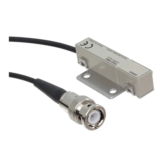
- Page 85 SECTION 7 Appendix V640-HS62 (Unit: mm) Four 3.5-dia. (mounting holes) Connector Coaxial cable, Dia.: 3.0, Length: 1.9 m Center of coil 39.2 Ferrite core Mounting Hole Dimensions Center of coil Four M3 or 3.5-dia. holes ± Item Specifications Transmission frequency 134 kHz Ambient temperature Operating: 0 to +40°C...
-
Page 86: Connection Examples
SECTION 7 Appendix Connection Examples V640-HAM11-ETN Connect the host device and Amplifier Unit using a LAN cable. Ethernet hub Host device Recommended: W4S1-05B(OMRON) CIDRW Head Amplifier Unit V640-HS61 V640-HAM11-ETN LAN cable LAN cable Host computer, device controller, etc. CIDRW Head... -
Page 87: Characteristic Data According To Conditions Of Use
The direction of the ID Tags will affect communications performance. Check the direction of the coils in the ID Tags before using the ID Tags. ■ V640-HAM11-ETN • Coaxial Mounting (RI-TRP-DR2B) • READ... - Page 88 SECTION 7 Appendix • Coaxial Mounting (RI-TRP-DR2B) • READ Communications Area (READ) Measurement point Distance in Z direction (mm) • WRITE Communications Area (WRITE) Measurement point Distance in Z direction (mm) CIDRW System User’s Manual...
- Page 89 SECTION 7 Appendix • Parallel Mounting (RI-TRP-DR2B) • READ Communications Area (READ) Measurement point Distance in X direction (mm) • WRITE Communications Area (WRITE) Measurement point Distance in X direction (mm) CIDRW System User’s Manual...
- Page 90 SECTION 7 Appendix • Parallel Mounting (RI-TRP-DR2B) • READ Communications Area (READ) Measurement point Distance in Z direction (mm) • WRITE Communications Area (WRITE) Measurement point Distance in Z direction (mm) CIDRW System User’s Manual...
- Page 91 SECTION 7 Appendix • Vertical Mounting (RI-TRP-DR2B) • READ Communications Area (READ) Measurement point Distance in X direction (mm) • WRITE Communications Area (WRITE) Measurement point Distance in X direction (mm) CIDRW System User’s Manual...
- Page 92 SECTION 7 Appendix • Vertical Mounting (RI-TRP-DR2B) • READ Communications Area (READ) Measurement point Distance in Z direction (mm) • WRITE Communications Area (WRITE) Measurement point Distance in Z direction (mm) CIDRW System User’s Manual...
- Page 93 SECTION 7 Appendix • Coaxial Mounting (RI-TRP-WR2B) • READ Communications Area (READ) Measurement point -200 -200 -150 -100 Distance in X direction (mm) • WRITE Communications Area (WRITE) Measurement point -200 -150 -100 Distance in X direction (mm) CIDRW System User’s Manual...
- Page 94 SECTION 7 Appendix • Coaxial Mounting (RI-TRP-WR2B) • READ Communications Area (READ) Measurement point -200 -150 -100 Distance in Z direction (mm) • WRITE Communications Area (WRITE) Measurement point -200 -150 -100 Distance in Z direction (mm) CIDRW System User’s Manual...
- Page 95 SECTION 7 Appendix • Parallel Mounting (RI-TRP-WR2B) • READ Communications Area (READ) Measurement point -200 -150 -100 Distance in X direction (mm) • WRITE Communications Area (WRITE) Measurement point -200 -150 -100 Distance in X direction (mm) CIDRW System User’s Manual...
- Page 96 SECTION 7 Appendix • Parallel Mounting (RI-TRP-WR2B) • READ Communications Area (READ) Measurement point -200 -150 -100 Distance in Z direction (mm) • WRITE Communications Area (WRITE) Measurement point -200 -150 -100 Distance in Z direction (mm) CIDRW System User’s Manual...
- Page 97 SECTION 7 Appendix • Vertical Mounting (RI-TRP-WR2B) • READ Communications Area (READ) Measurement point -200 -150 -100 Distance in X direction (mm) • WRITE Communications Area (WRITE) Measurement point -200 -150 -100 Distance in X direction (mm) CIDRW System User’s Manual...
- Page 98 SECTION 7 Appendix • Vertical Mounting (RI-TRP-WR2B) • READ Communications Area (READ) Measurement point -200 -150 -100 Distance in Z direction (mm) • WRITE Communications Area (READ) Measurement point -200 -150 -100 Distance in Z direction (mm) CIDRW System User’s Manual...
- Page 99 SECTION 7 Appendix ■ V640-HAM11-L-ETN • Coaxial Mounting (RI-TRP-DR2B) • READ Communications Area (READ) Measurement point -180 -160 -140 -120 -100 Distance in X direction (mm) • WRITE Communications Area (READ) Measurement point -180 -160 -140 -120 -100 Distance in X direction (mm) CIDRW System User’s Manual...
- Page 100 SECTION 7 Appendix • Coaxial Mounting (RI-TRP-DR2B) • READ Communications Area (READ) Measurement point -180 -160 -140 -120 -100 Distance in Z direction (mm) • WRITE Communications Area (READ) Measurement point -180 -160 -140 -120 -100 Distance in Z direction (mm) CIDRW System User’s Manual...
- Page 101 SECTION 7 Appendix • Parallel Mounting (RI-TRP-DR2B) • READ Communications Area (READ) Measurement point -180 -160 -140 -120 -100 Distance in X direction (mm) • WRITE Communications Area (READ) Measurement point -180 -160 -140 -120 -100 Distance in X direction (mm) CIDRW System User’s Manual...
- Page 102 SECTION 7 Appendix • Parallel Mounting (RI-TRP-DR2B) • READ Communications Area (READ) Measurement point -180 -160 -140 -120 -100 Distance in Z direction (mm) • WRITE Communications Area (READ) Measurement point -180 -160 -140 -120 -100 Distance in Z direction (mm) CIDRW System User’s Manual...
- Page 103 SECTION 7 Appendix • Vertical Mounting (RI-TRP-DR2B) • READ Communications Area (READ) Measurement point -180 -160 -140 -120 -100 Distance in X direction (mm) • WRITE Communications Area (READ) Measurement point -180 -160 -140 -120 -100 Distance in X direction (mm) CIDRW System User’s Manual...
- Page 104 SECTION 7 Appendix • Vertical Mounting (RI-TRP-DR2B) • READ Communications Area (READ) Measurement point -180 -160 -140 -120 -100 Distance in Z direction (mm) • WRITE Communications Area (READ) Measurement point -180 -160 -140 -120 -100 Distance in Z direction (mm) CIDRW System User’s Manual...
- Page 105 SECTION 7 Appendix • Coaxial Mounting (RI-TRP-WR2B) • READ Communications Area (READ) Measurement point -200 -150 -100 Distance in X direction (mm) • WRITE Communications Area (READ) Measurement point Distance in X direction (mm) CIDRW System User’s Manual...
- Page 106 SECTION 7 Appendix • Coaxial Mounting (RI-TRP-WR2B) • READ Communications Area (READ) Measurement point -200 -150 -100 Distance in Z direction (mm) • WRITE Communications Area (READ) Measurement point -200 -150 -100 Distance in Z direction (mm) CIDRW System User’s Manual...
- Page 107 SECTION 7 Appendix • Parallel Mounting (RI-TRP-WR2B) • READ Communications Area (READ) Measurement point -200 -150 -100 Distance in X direction (mm) • WRITE Communications Area (READ) Measurement point -200 -150 -100 Distance in X direction (mm) CIDRW System User’s Manual...
- Page 108 SECTION 7 Appendix • Parallel Mounting (RI-TRP-WR2B) • READ Communications Area (READ) Measurement point -200 -150 -100 Distance in Z direction (mm) • WRITE Communications Area (READ) Measurement point -200 -150 -100 Distance in Z direction (mm) CIDRW System User’s Manual...
- Page 109 SECTION 7 Appendix • Vertical Mounting (RI-TRP-WR2B) • READ Communications Area (READ) Measurement point -200 -150 -100 Distance in X direction (mm) • WRITE Communications Area (READ) Measurement point -200 -150 -100 Distance in X direction (mm) CIDRW System User’s Manual...
- Page 110 SECTION 7 Appendix • Vertical Mounting (RI-TRP-WR2B) • READ Communications Area (READ) Measurement point -200 -150 -100 Distance in Z direction (mm) • WRITE Communications Area (READ) Measurement point -200 -150 -100 Distance in Z direction (mm) CIDRW System User’s Manual...
-
Page 111: For Coaxial Installation
SECTION 7 Appendix Mutual Interference Distances (Reference Only) If Amplifier Units are connected using multidrop connections and multiple CIDRW Heads are used, the CIDRW Heads will not process commands simultaneously. In this case, install the CIDRW Heads at least 0.1 m apart from each other. Distance between Antennas and Changes in Communications Distances (Reference Only) •... - Page 112 SECTION 7 Appendix Influence of Background Metals (Reference Only) The CIDRW Head can also communicate from an opening in a ceiling panel (metal body). Metal body (material: AL, SUS) (Thickness: 1 mm) However, ensure the distances indicated below between the CIDRW Head and the metal body. If you do not ensure these distances the communications distance will be substantially shortened.
- Page 113 SECTION 7 Appendix Communications Time Regardless of whether SECS is used or not, take the time required for processing between the host device and Amplifier Units into account when designing the system. Host Response Command Amplifier Unit Communications time Time Description Communications time This is the time required for communications between an ID Tag and the CIDRW Head.
- Page 114 SECTION 7 Appendix The graph for communications time for communications between the ID Tag and CIDRW Head, and TAT (when the baud rate is 9600 bps), is shown below. The communications time and TAT, however, may increase substantially according to the conditions of use.
- Page 115 SECTION 7 Appendix BYTE WRITE 8500 8000 7500 7000 Communications time 6500 6000 5500 5000 4500 4000 3500 3000 2500 2000 1500 1000 Number of bytes processed Please confirm beforehand, there is a difference in comparision with V640-HAM11-V2 and V640- HAM12 in communication time.
- Page 116 10. NOISE MEASUREMENT command (applies only when SECS is not used) Refer to page 51. ■ V640-HAM11-ETN Relationship between noise level and communications distance (reference values) (MAX) (Max.)
-
Page 117: Id Tag Memory Maps
SECTION 7 Appendix ID Tag Memory Maps The memory maps of the RI-TRP-DR2B(-30) and RI-TRP-WR2B(-30) ID Tags are given below. ■ RI-TRP-DR2B(-30) Example of data ID Tag Memory Map segment settings Page 8 bytes/1 page DATASEG LENGTH Carrier ID Carrier (16 byte) "S01"... -
Page 118: Regular Inspection
SECTION 7 Appendix Regular Inspection In order to maintain optimum performance of the functions of the CIDRW system, daily and periodic inspections are necessary. Inspection item Detail Criteria Tools required Supply voltage fluctuation Check that the supply voltage fluctuation To be within supply voltage rating. Multimeter at the power supply terminal block is within the permissible range. -
Page 119: Ascii Code Table
SECTION 7 Appendix ASCII Code Table Leftmost bits b8 to b5 0000 1001 0010 0011 0100 0101 0110 0111 1000 1101 1010 1011 1100 1101 1110 1111 Right- most bits b4 to b1 Line 0000 TC7(DLE) (SP) 0001 TC1(SOH) DC 0010 TC2(STX) "... -
Page 120: Protective Construction
SECTION 7 Appendix Protective Construction is governed by the test methods described below. Check in advance the seal characteristics under the actual environment and conditions of use. IP is the abbreviation of International Protection. ■ IEC (International Electrotechnical Commission) Standard (IEC60529: 1989-11) (A) First numeral in code: Class of protection against entry of solid foreign material Class Degree of protection... - Page 121 SECTION 7 Appendix Class Degree of protection Outline of test methods (tests using water) Protection against spraying The product suffers no ill Using the test apparatus 0.07 L/min. water effects from a water spray shown in the figure to the per hole in the directed at it at up to 60°...
-
Page 122: Section 8 Revision History
Revision History A manual revision code appears as a suffix to the catalog number on the front cover of the manual. Cat. No. Z308-E1-02 Revision code The following table outlines the changes made to the manual during each revision. Page numbers refer to the previous version. - Page 123 IL 60173-5302 U.S.A. Carl-Benz-Str. 4, D-71154 Nufringen, Germany Tel: (1) 847-843-7900/Fax: (1) 847-843-7787 Tel: (49) 7032-811-0/Fax: (49) 7032-811-199 © OMRON Corporation 2010 All Rights Reserved. OMRON (CHINA) CO., LTD. OMRON ASIA PACIFIC PTE. LTD. In the interest of product improvement, Room 2211, Bank of China Tower, No.
Need help?
Do you have a question about the V640-HAM11-ETN and is the answer not in the manual?
Questions and answers