Omron V640 User Manual
V640 series amplifier unit, cidrw head, cidrw controller, cidrw controller
Hide thumbs
Also See for V640:
- User manual (144 pages) ,
- Operation manual (46 pages) ,
- Product manual (12 pages)

Related Manuals for Omron V640


Summary of Contents for Omron V640
- Page 1 AMPLIFIER UNIT Cat. No. Z218-E1-01A V640-HAM12 CIDRW HEAD V640-HS62 CIDRW CONTROLLER V700-L22 LINK UNIT V700-L11 V640 SERIES USER’S MANUAL...
-
Page 2: Introduction
Please observe the following points when operating the V640 Series: • Please read and understand the content of this manual before using the system. • After reading this manual, store it in a handy location for easy reference whenever necessary. - Page 3 The following are some examples of applications for which particular attention must be given. This is not intended to be an exhaustive list of all possible uses of the products, nor is it intended to imply that the uses listed may be suitable for the products: •...
-
Page 4: Performance Data
PERFORMANCE DATA Performance data given in this document is provided as a guide for the user in determining suitability and does not constitute a warranty. It may represent the result of OMRON’s test conditions, and the users must correlate it to actual application requirements. -
Page 5: Cidrw System
Table of Contents/Precautions in using the product Introduction SECTION 1 Product Outline Installation and Connections/Wiring SECTION 2 SECTION 3 Preparing for Communications Reading from/Writing to ID Tags SECTION 4 SECTION 5 Troubleshooting Appendix SECTION 6 CIDRW System V640-HAM12 Amplifier Unit... -
Page 6: Applicable Standards
Radio: EN300330 (2001) EMC: EN301489-3 (EN301489-1) Safety: EN61010-1:1993+A2 Note: When using the CIDRW System in Europe, the connecting cable between the CIDRW and the DC power supply must be 3 m or less. Applicable SEMI Standards The CIDRW System complies with the following SEMI standards. -
Page 7: Precautions For Safe Use
Please observe the following precautions for safe use of the products. • Do not allow water to enter or insert wires through gaps in the case. This could cause fire or electric shock. • In the event of a malfunction, stop using the product immediately, turn off the power, and consult your OMRON dealer. - Page 8 (power supply ICs) generate electrical waves (noise) that interfere with communications with ID Tags. If you are using the product in the vicinity of any of these devices, check the effect on communications in advance.
- Page 9 ■ Startup Precaution Never turn OFF the power supply while the CIDRW Controller is starting, including when power is turned ON, when the mode is changed, or when the CIDRW Controller is being reset. Doing so may damage the CIDRW Controller.
-
Page 10: To Users Of Model V700-L21
MID cannot be specified with an ID write request (S18F11). With the V700-L21, the MID to be read or written is consigned to an area fixed at 16 bytes. If the specified data length in the ID write request (S18F11) is less than 16 bytes, NULs are added in internal processing to make the total up to 16 bytes. -
Page 11: Editor's Note
Visual Aids Indicates an explanation of a point that must be observed to ensure that the product is capable of its proper functions and perfor- mance. Read this information carefully and follow the cautions. If the product is used incorrectly, data or the equipment itself could be destroyed. - Page 12 INTRODUCTION MEMO CIDRW System User’s Manual...
-
Page 13: Table Of Contents
SECTION 2 Installation and Connections/Wiring Installation Connections and Wiring SECTION 3 Preparing for Communications Set the Communications Conditions for the CIDRW Controller Set the Communications Conditions for Amplifier Units Set the Communications Conditions for Link Units Communications Test SECTION 4 Reading from/Writing to ID Tags... - Page 14 SECTION 5 Troubleshooting When SECS is Used When SECS is Not Used SECTION 6 Appendix Specifications and Dimensions System Configuration Examples Characteristic Data depending on Conditions of Use Data Segment Area Regular Inspection SECS Protocol Specifications ASCII Code Table Protective Construction CIDRW System User’s Manual...
-
Page 15: Section 1 Product Outline
SECTION 1 Product Outline What is a CIDRW System? Features System Configuration Component Names and Functions Flowchart for Getting Started CIDRW System User’s Manual... -
Page 16: What Is A Cidrw System
Product Outline What is a CIDRW System? The CIDRW system writes data to, and reads data from, the carrier IDs (ID Tags) mounted on the carriers (FOUP) in semiconductor manufacturing processes without contacting these ID Tags. CIDRW is the abbreviation of Carrier ID Reader/Writer and this abbreviation is used throughout this manual. -
Page 17: Features
SECTION 1 Product Outline Features ■ CIDRW Systems that Conform to SEMI Standards (SEMI E99, E5, E4) CIDRW System Conforming to SEMI Standards CIDRW Controller V700-L22 ID Tag Host RI-TRP-DR2B/ CIDRW Head Amplifier Unit RI-TRP-WR2B V640-HS62 V640-HAM12 (Made by Texas... -
Page 18: System Configuration
104 Using Link Units (V700-L11) to make connections makes it possible to remove and replace just the relevant Amplifier Unit while leaving the power to the CIDRW system on in the event of a failure or during mainte- nance. -
Page 19: Component Names And Functions
3: Setting mode, selected to set information such as the communication conditions. When the switch on the bottom face of the Controller cannot be accessed, the opera- tion mode can be changed from the host device while the switch is left at the 0 set- ting. -
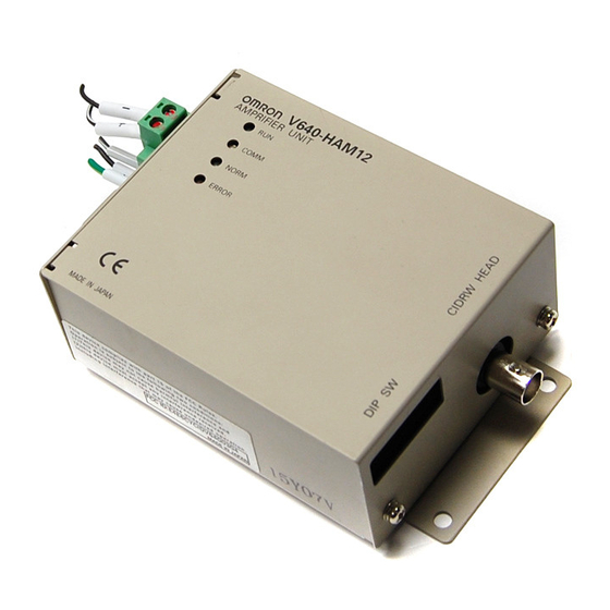
Page 20: Amplifier Unit V640-Ham
Connect to the 24 VDC power supply. nector RS-485 port When using multiple CIDRW Heads, connect this to the RS-485 port of another Amplifier Unit or to the multi-connection port of a Link Unit. RS-232C port Connected to a CIDRW Controller or a host device. -
Page 21: Cidrw Head V640-Hs
Product Outline CIDRW Head V640-HS62 V640-HS62 CIDRW HEAD MADE IN JAPAN Name Function Antenna Used to communicate with ID Tags. Antenna center This is the center of the communications area. Connector Connect to an Amplifier Unit. CIDRW System User’s Manual... - Page 22 Turns ON when an error occurs during data communications with the host device or head. Host device connection port This is a port for connecting to the CIDRW Controller via an RS-232C interface. A dust (RS-232C) cover is fitted on shipment from the factory. Remove this cover before using the port.
-
Page 23: Flowchart For Getting Started
Installation Refer to page 22. Connection and Wiring Refer to page 27. Set the Communications Conditions for the CIDRW Controller Refer to page 44. Set the Communications Conditions for Amplifier Units Refer to page 57. Set the Communications Conditions for Link Units Refer to page 59. - Page 24 SECTION 1 Product Outline When SECS is Used Refer to page 66. When SECS is Not Used Refer to page 77. When you Encounter a Problem... When SECS is Used Refer to page 88. List of Error Messages Refer to page 88.
-
Page 25: Section 2 Installation And Connections/Wiring
SECTION 2 Installation and Connections/Wiring Installation Connections and Wiring CIDRW System User’s Manual... -
Page 26: Installation
Installation CIDRW Controller There is a switch for selecting the operation mode (Normal Operation mode <-> Setting mode) on the bottom face of the CIDRW Controller. Set the communications conditions in the Setting mode (switch position 3) before mounting the CIDRW Controller. - Page 27 SECTION 2 Installation and Connections/Wiring Amplifier Unit Use spring washers and flat washers with the four M4 screws when mounting the Amplifier Unit. Mounting dimensions (Unit: mm) 115±0.5 4-M4 V640-HAM12 AMPLIFIER UNIT COMM NORM ERROR MADE IN JAPAN Tighten the M4 screws with a torque not exceeding 1.2 N·m.
- Page 28 The communications distances for reading and writing are not the same; the distance is shorter for writing. Therefore, when data is to be both read and written, take the distance for writing as the refer- ence distance when installing the CIDRW Head and the ID Tag.
-
Page 29: Influence Of Background Metal On Id Tag
The noise levels in the vicinity of the CIDRW Head can be determined with the environmental noise measurement com- mand (applies only when SECS is not used) . - Page 30 Two M4 or 4.2-dia. holes • Tighten the M4 screws with a torque not exceeding 1.2 N·m. • Do not apply organic solvents used with screw locking agents at the locations where the screws are inserted. CIDRW System User’s Manual...
-
Page 31: Connections And Wiring
Connect the wires to the 24 VDC power supply terminals and frame ground terminal. Ground to 100 Ω or less. 24 VDC • Crimp terminals The terminal screws on the terminal block are M3 size. Use appropriate crimp terminals for M3 screws as shown below. Crimp terminals Shape... - Page 32 SECTION 2 Installation and Connections/Wiring ■ SECS port The method for wiring for communications with a host device via the SECS port is explained here. Host CIDRW Controller To the RS-232 port To the SECS port • Connector The SECS port on the Controller is a D-SUB 9-pin connector. The pin arrangement is shown below.
- Page 33 The cable length should be no greater than 15 m. CIDRW Controller PC/AT Computer V700-L22 D-SUB, 9-pin D-SUB, 9-pin Socket type #4-40 Socket type #4-40 Name Pin No. Pin No. Name Ground shielded wires either at the CIDRW Controller side or at the PC/AT side. CIDRW System User’s Manual...
-
Page 34: Connector For Connecting A Cidrw Head
Ground to 100 Ω or less 24 VDC • The grounding wire should be connected to a ground exclusive to the Amplifier Unit. If the grounding wire is shared with another unit, or connected to a beam in a building, there may be adverse effects. - Page 35 Connector for RS-485 port Phoenix Contact MSTB2.5/2-STF-5.08 • Dedicated power supply cable Use an AWG20 - 24 cable. Use a dedicated tool for crimping the cable to the connector pins. Recommended crimping tool Manufacturer Model Tyco Electronics 919601-1 • Power supply unit Use a power supply unit that satisfies the following conditions.
-
Page 36: Rs-232C Port
SECTION 2 Installation and Connections/Wiring ■ RS-232C Port The method for connecting a CIDRW Controller or host device via the RS-232C port is explained here. CIDRW Controller Amplifier Unit To the RS-232C port To ID port Host Amplifier Unit To the RS-232C port To the RS-232C port •... - Page 37 Amplifier unit CIDRW Controller V640-HAM12 V700-L22 D-SUB, 9-pin D-SUB, 9-pin Socket type Socket type #4-40 #4-40 Name Pin No. Pin No. Name Ground shielded wires either at the amplifier unit side or at the CIDRW side. CIDRW System User’s Manual...
- Page 38 RS signal control method at the host device In a 1:N connection, the RS signals generated from the host device by normal control must be input as CS signals. Turn the RS signals OFF within 15 ms after the completion of data transmission. Correct communications will not be possible without this control.
-
Page 39: Rs-485 Port
To the RS-232C port The maximum total length of RS-485 cable is 50 m. • Connector Prepare a V640-A90 (can be purchased as an accessory) as the connector for the RS-485 port on the Amplifier Unit. Refer to page 31. - Page 40 Disconnecting the connector Fully loosen the two screws, then grip the projections on the connector and pull it straight out. If it is difficult to pull the connector out, press down on the Amplifier Unit while pulling on the connector.
-
Page 41: Power Supply
Opening the cover on the top face of the Link Unit exposes the power supply terminals. 24 VDC • Crimp terminals The terminal screws on the terminal block are M3 size. Use appropriate crimp terminals for M3 screws as shown below. Crimp terminals... -
Page 42: Host Connection Port
To host device port To the RS-232C port • Connector The host device connection port on the Link Unit is a D-SUB, 9-pin connector. The pin arrangement is shown below. The connector rim does not have electrical continuity with the GR (frame ground) termi- nal in the multi-connection port. - Page 43 CO-MA-VV-SB 5PX28AWG Connector Socket OMRON XM2D-0901 Hood XM2S-0913 • Wiring for connection to a CIDRW Controller The cable length should be no greater than 15 m. Link unit CIDRW Controller V700-L11 V700-L22 D-SUB, 9-pin, female D-SUB, 9-pin, female Socket type #4-40...
- Page 44 RS signal control method at the host device In a 1:N system using Link Units, the RS signals generated from the host device by normal control must be input as CS signals. Turn the RS signals OFF within 15 ms after the completion of data transmission. Correct communications will not be possible without this control.
- Page 45 SECTION 2 Installation and Connections/Wiring ■ Multi-connection port The method for connecting to an Amplifier Unit is explained here. Link Unit To multi-connection port Amplifier Unit To the RS-485 port • Connector Pin No. Name Function No wiring is required. (Short with terminal 2 within the circuit) No wiring is required.
- Page 46 Disconnecting the connector Fully loosen the two screws, then grip the projections on the connector and pull it straight out. If it is difficult to pull the connector out, press down on the Link Unit while pulling on the connector.
-
Page 47: Section 3 Preparing For Communications
SECTION 3 Preparing for Communications Set the Communications Conditions for the CIDRW Controller 44 Set the Communications Conditions for Amplifier Units Set the Communications Conditions for Link Units Communications Test CIDRW System User’s Manual... -
Page 48: Set The Communications Conditions For The Cidrw Controller
Switch to the Setting mode to set the communications conditions. There are two methods for switching the mode. Use the one that is appropriate for the circumstances. ■ Changing the Position of the Mode Switch on the Bottom of the Unit This is the convenient method for setting before mounting the unit. - Page 49 Use the host device's terminal software for the setting. The commands and communications conditions in the setting mode are unique to OMRON. They do not conform to the SEMI standards. For the terminal software, use Hyper Terminal, which is standard with Windows, or a similar program.
- Page 50 For the terminal software, use Hyper Terminal, which is standard with Windows, or a similar program. The RI-TRP-WR2B has a memory capacity of 8 bytes. Set the clear ID offset and the number of carrier ID bytes so that the memory capacity is not exceeded.
- Page 51 [0]. Check the sent data based on this information. A text file is created based on the data that is keyed in, as shown below, and this data can be conveniently transmitted using the terminal's text file send function.
- Page 52 Change the Carrier ID To read the carrier ID, the CID has to be specified within the area where the carrier ID can be set (CarrierIDField) within the ID tag's memory. This section explains the procedure for setting the carrier ID offset (attribute name: CarrierIDOffset) and the carrier ID size (bytes) (attribute name: CarrierIDLength) in the memory map of the ID tag.
-
Page 53: Change The Data Segment Area
The input parameter is checked and written. ::END ■ Check for Correct Setting The currently set data can be output so that you can check if it is correct. Send the parameter output command "::GET_E99SYS" ::GET_E99SYS from the host device. - Page 54 When writing is completed with an error The figure in square brackets [ ] indicates the line number where the error was first detected. If a parity error is detected in the received char- SETUP_FAILED [2]_ acters, this figure is [0].
- Page 55 SECTION 3 Preparing for Communications ■ Check for Correct Setting The currently set data can be output so that you can check if it is correct. Send the parameter output command "::GET_SEG" from ::GET_SEG the host device. The data segment area is displayed.
-
Page 56: Change The Response Time-Out Time
Change the response time-out time In the initial settings of the CIDRW Controller, when ID Tag (RI-TRP-DR2B, made by Texas Instru- ments) data is read or written, a response time-out may occur. Be sure to set the response time-out time to 10 s. - Page 57 This can cause the system to stop operating correctly. Set Software Revisions The operations of the V700-L22 can be changed to match those of the previous model, the V700-L21. The commands, and the parameters that can be set are indicated below.
-
Page 58: Return To The Normal Operation Mode
Start up in the Normal Operation mode. Even if you restart with the mode switch left at the 3 position, or send a reset command "::EXIT," the Controller will start in the Setting mode. To switch to Normal Operation mode, you must set the mode switch to 0. - Page 59 Command input Explanation Parameter designation (Tag name) = (Set value) <CRLF> Specify the parameter value corresponding to the tag name. Parameter confirmation ::END Checks the parameter designations that have been received so far and, if there is no error, confirms the settings.
- Page 60 SECTION 3 Preparing for Communications Tag Name List Classification Parameter Tag name Setting range Default setting Response timeout 10.0 s (fixed) 2.5 s time Carrier ID offset CIDOF 00 - 15 Carrier ID length CIDLEN 01 - 16 CIDRW System...
-
Page 61: Set The Communications Conditions For Amplifier Units
Option Description Invalid Set ON at both of the end units in a multidrop system, and OFF at all the other units. If there is only one unit, set ON. Valid If there is a possibility that one of multiple Amplifier Units in use may be used independently, turn the termi- nators of all the Amplifier Units OFF and fit external terminators close to the units at both ends. - Page 62 SECTION 3 Preparing for Communications Communications conditions Item Specifications Standard conformed to RS-232C Communications control protocol OMRON’s exclusive 1:N or 1:1 protocol Synchronization method Start-stop synchronization Baud rate Set using a DIP switch Frame composition Start bit Data bits Parity bit...
-
Page 63: Set The Communications Conditions For Link Units
Node No. Baud rate Always OFF (Not used in this CIDRW system) Node No. (fixed) DIP-SW The node numbers for Link Units are fixed. Check that DIP switches 1to 5 are all ON. Baud rate DIP-SW Option Description 38400 bps Use a consistent baud rate setting within the same system configuration. - Page 64 SECTION 3 Preparing for Communications Communications conditions Item Specifications Standard conformed to RS-232C Communications con- 1:N protocol exclusive to OMRON trol protocol Synchronization Start-stop synchronization method Baud rate Set using a DIP switch Frame composition Start bit Data bits Parity bit...
-
Page 65: Communications Test
• Connection between host device and CIDRW Controller Send Are You There Request message "S1, F1" from the host device. If it is correctly connected, On Line Data "S1, F2" will be sent from the CIDRW Controller. • Connection between the CIDRW Controller and Amplifier Unit The connection between the CIDRW Controller and Amplifier Unit is checked automatically. -
Page 66: When Secs Is Used
SECTION 3 Preparing for Communications ID Tag ↔ CIDRW System Communications Test Send a command from the host device and check that normal communication with the ID Tag is possi- ble. ■ When SECS is Used • Read ID The host device sends a Read ID Request message to the CIDRW Controller for Head 1. The CIDRW Head 1 reads the ID, and the CIDRW Controller returns the ID to the host device. - Page 67 • Write Data The host device sends a Write Data Request message to the CIDRW Controller for Head 1 and Data- Seg S02. The CIDRW Head 1 writes the data, and the CIDRW Controller returns the results to the host device.
- Page 68 FCS CR code 1 2 3 4 5 6 7 8 9 0 1 2 3 4 5 6 1 1 2 2 3 3 4 4 5 5 6 6 7 7 8 8 0 7 0Dh • Write Writing data to page 8 and page 10 of node No.1:...
-
Page 69: When Secs Is Used When Secs Is Not Used
SECTION 4 Reading from/Writing to ID Tags When SECS is Used When SECS is Not Used CIDRW System User’s Manual... -
Page 70: Message Specifications
Reading from/Writing to ID Tags When SECS is Used The SEMI standards are subject to revision. You must refer to the actual standards. • SEMI E99 THE CARRIER ID READER/WRITER FUNCTIONAL STANDARD • SEMI E5 EQUIPMENT COMMUNICATION STANDARD 2 MESSAGE CONTENT (SECS II) •... - Page 71 "Illegal format" here means that there is a problem with the message composition, such as illegal attributes, or insuffi- cient or too many items. If other problems relating to the item contents arise, the response is SSACK = "CE" (communi- cations error).
- Page 72 = 0, s = 0, SSACK = "CE" communications error • When head attributes are specified with TARGET = "00" or CIDRW Controller attributes are specified with TARGET <> "00": n = 0, s = 0, SSACK = "CE" communications error •...
- Page 73 = 0, SSACK = "CE" communications error • When illegal attribute data is specified: s = 0, SSACK = "CE" communications error • If the status of SSACK is other than "NO" (normal), the List of Status will comprise zero items. CIDRW System User’s Manual...
- Page 74 • When DATASEG is specified as "0" and a character string, the size of data determined by the DATALENGTH setting is read, starting from the address indicated by the DATASEG setting. If DATALENGTH = 0, data is read up to the end of the data area.
- Page 75 4.<DATA> • If DATASEG is specified as "0" and a character string, a size of data corresponding to the DATALENGTH setting and starting from the address within the data area indicated by the DATASEG setting is written (address specification). If DATALENGTH = 0, data is written up to the end of the data area.
- Page 76 Write ID Request S,H→E,reply 1.<TARGETID> "01"-"31" 2.<MID> • If an MID that is under the length set for the CarrierIDlength attribute is specified, an error occurs and the MID data is not written. Data Segment Area Refer to page 125. S18,F12 Write ID Acknowledge S,H←E...
- Page 77 = 0, SSACK = "CE" communications error • When OperationalStatus is BUSY: s = 0, SSACK = "EE" execution error • If the status of SSACK is other than "NO" (normal), the List of Status will comprise zero items. CIDRW System User’s Manual...
- Page 78 = 0, SSACK = "CE" communications error • When SSCMD is invalid: s = 0, SSACK = "CE" communications error • If the status of SSACK is other than "NO" (normal), the List of Status will comprise zero items. • Subsystem command (PerformDiagnostics) S18,F13 Subsystem Command Request (PerformDiagnostics) S,H→E,reply...
- Page 79 "00" (fixed) 2.<SSCMD> "Reset" 3.L,0 S18,F14 Subsystem Command Acknowledge (Reset) S,H←E 1.<TARGETID> "00" 2.<SSACK> 3.L,0 • When the specified target is invalid: SSACK = "CE" communications error • When SSCMD is invalid: SSACK = "CE" communications error CIDRW System User’s Manual...
- Page 80 SECTION 4 Reading from/Writing to ID Tags ■ Operation Conditions The response messages and response codes (SSACK) in each state are shown below. State Operating Initializing Maintenance Message Function IDLE BUSY S1,F1 OnlineRequest S1,F0 S1,F2 S1,F2 S1,F2 S18,F11 WriteID S18,F0...
-
Page 81: When Secs Is Not Used
⋅ ⋅ ⋅ Meaning of FCS (frame check sequence) This is two ASCII code characters obtained by conversion from the 8-bit exclusive logical sum (EOR) of the characters from the character immediately after SOH to the character immediately before FCS. - Page 82 SECTION 4 Reading from/Writing to ID Tags Example: Reading the data of page 1 and page 2 of node No.1 Command Calculation range (ASCII conversion) CIDRW System User’s Manual...
-
Page 83: Command Code List
Communicate with the host device only after confirming that the CIDRW Controller has started. Also, unstable signals may occur at the host interface when the CIDRW Controller is started. When initializing operation, clear the reception buffer at the host device or take other suitable methods to clear unwanted signals. - Page 84 SOH, node number, and FCS data, as described in the previous pages. ■ READ Reads any pages of data from the ID Tag. The maximum number of pages that can be read at one time is 16.
- Page 85 FCS CR code 1 2 3 4 5 6 7 8 9 0 1 2 3 4 5 6 1 1 2 2 3 3 4 4 5 5 6 6 7 7 8 8 0 7 0Dh ■ WRITE Data is written in page units to the ID Tag.
- Page 86 1 0 2 0 0 0 0 0 0 0 A 0 0 1 1 2 2 3 3 4 4 5 5 6 6 7 7 8 8 0 1 2 3 4 5 6 7 8 9 A...
-
Page 87: Same Write
Node No. Page designation Write data code 0 3 0 0 0 0 0 7 F F F C 0 0 0 0 0 0 0 0 0 0 0 0 0 0 0 0 Binary notation Response Response Node No. - Page 88 Reading from/Writing to ID Tags ■ Byte Write Writes data to any specified number of bytes starting from the address specified in the ID Tag. The maximum number of bytes that can be written at one time is 128. Command...
- Page 89 ■ TEST Performs a communication test on communications between the host device and Amplifier Unit. When an Amplifier Unit receives a test command, it sends the response code and command test data to the host device as the response. Command Test data Node No.
-
Page 90: Noise Measurement
Response Sends the response made immediately before again. ■ Noise measurement The levels of noise in the vicinity of the CIDRW Head are measured and the noise level is expressed numerically in the range "00" to "99." Command Node No. -
Page 91: Section 5 Troubleshooting
SECTION 5 Troubleshooting When SECS is Used When SECS is Not Used CIDRW System User’s Manual... -
Page 92: When Secs Is Used
Data Too Long S,H←E Abort Transaction Controller Indicators If an error or alarm has occurred at the CIDRW Controller, the LEDs on the front of the Controller light. Name Function OPERATING (green) Lit when the operation status (status model) of the CIDRW system is operating. -
Page 93: Troubleshooting
When all the LEDs are lit or flashing Refer to page 90. Check if the settings of the CIDRW Controller and Amplifier Unit are correct. When the CIDRW Controller fails to respond to messages sent to it Refer to page 91. - Page 94 • Mistake in the details of the items in the message (The node number of an amplifier that is not set was specified as the TARGET ID, or a segment name that is not set has been specified for DATASEG.) •...
- Page 95 • When an error unrelated to message transmission and responses occurs There is a mistake in the settings of the CIDRW Controller and Amplifier Unit. After taking the appropriate corrective action, restart the CIDRW Controller and Amplifier Unit.
-
Page 96: Setting Mode
POWER OPERATING ALARMS BUSY ERROR Terminal initial screen of the host device after startup in the Setting mode SETUP_START <L22 ><XXX.XX, YYY.YY> Model number Software Revision Level Hardware Revision Level Terminal screen when parameter setting has been completed without error... - Page 97 SETUP_FAILED [ The parameters are not updated. The figure in square brackets [ ] indicates the line number where the error was first detected. If a parity error is detected in the received characters, this figure is [0]. • When the CIDRW Controller fails to respond to messages sent to it There is a mistake in the CIDRW Controller settings or the sent parameters.
-
Page 98: When Secs Is Not Used
SECTION 5 Troubleshooting When SECS is Not Used Errors are indicated by the presence or absence of a response to an Amplifier Unit command, and by the indicators. List of Error Messages Response Type Name Description code Host communi- Format error There is a mistake in the command format. -
Page 99: From Installation To Trial Operation
Troubleshooting Operation Check Flowchart ■ From Installation to Trial Operation Errors are indicated by whether or not a response to the test command is received and by the status of the Amplifier Unit indicators. Error occurrence An error has occurred at the Amplifier Unit. - Page 100 Method using RS signal control at the host device In a 1:N connection using Link Units, the RS signals generated from the host device by normal control must be input as CS signals. Turn the RS signals OFF within 15 ms after the completion of data transmission. Correct communications will not be possible without this control.
-
Page 101: From Trial Operation To Communications
SECTION 5 Troubleshooting ■ From Trial Operation to Communications Errors are indicated by the status of the indicators after transmission of the write command, and by the response code of the response. Error occurrence Write command sent An error has occurred at the Amplifier Unit. - Page 102 • Settings of the ID Tags used (The ID Tag lock function is used.*) • Environment of use of the ID Tags (ID Tag breakage due to use in unanticipated ways) * The ID Tag has a lock function, but the amplifier unit has no function for locking an ID Tag. CIDRW System...
-
Page 103: Section 6 Appendix
SECTION 6 Appendix Specifications and Dimensions System Configuration Examples When SECS is Not Used Characteristic Data depending on Conditions of Use Data Segment Area Regular Inspection SECS Protocol Specifications ASCII Code Table Protective Construction CIDRW System User’s Manual... -
Page 104: Specifications And Dimensions
50 MΩ min. between power supply terminals and the frame ground terminal (500 VDC M) Dielectric strength Leak current not to exceed 3.5 mA on application of 500 VAC (50/60 Hz for 1 minute) between both power supply terminals and the frame ground terminal Vibration resistance Frequency: 10 to 150 Hz;... - Page 105 20 MΩ min. between power supply terminals and the frame ground terminal (100 VDC M) Dielectric strength Leak current not to exceed 5 mA on application of 1000 VAC (50/60 Hz for 1 minute) between both power supply terminals and the frame ground terminal Vibration resistance Frequency: 10 to 150 Hz;...
- Page 106 Insulation resistance 20 MΩ min. between all terminals and the case (100 VDC M) Dielectric strength Leak current not to exceed 5 mA on application of 1000 VAC (50/60 Hz for 1 minute) between all terminals and the case Vibration resistance Frequency: 10 to 150 Hz;...
- Page 107 50 MΩ min. between power supply terminals and the frame ground terminal (500 VDC M) Dielectric strength Leak current not to exceed 5 mA on application of 1000 VAC (50/60 Hz for 1 minute) between power supply terminals and the frame ground terminal Vibration resistance Frequency: 10 to 150 Hz;...
-
Page 108: System Configuration Examples
Link Unit (V700-L11) between the CIDRW Controller and the first Amplifier Unit. If an Amplifier Unit on the end of the network is removed, be sure to turn ON the terminating resistance on the Amplifier Unit that will end up on the end of the network while the Amplifier Unit is removed. - Page 109 Link Unit (V700-L11) between the CIDRW Controller and the first Amplifier Unit. If an Amplifier Unit on the end of the network is removed, be sure to turn ON the terminating resistance on the Amplifier Unit that will end up on the end of the network while the Amplifier Unit is removed.
-
Page 110: Characteristic Data Depending On Conditions Of Use
The figures given below for communications areas (communications distances) are reference values only and cannot be guaranteed. The maps of communications areas will vary according to the ID tags that you use, the background metals, the ambient noise, the effects of temperature and so on, and should be thoroughly confirmed on installation. - Page 111 ■ Coaxial Mounting (RI-TRP-DR2B) • READ Communications Areas (READ) Measurement point −180 −160 −140 −120 −100 −80 −60 −40 −20 Distance in Z direction (mm) • WRITE Communications Areas (WRITE) Measurement point −180 −160 −140 −120 −100 −80 −60 −40 −20...
- Page 112 ■ Parallel Mounting (RI-TRP-DR2B) • READ Communications Areas (READ) Measurement point −180 −160 −140 −120 −100 −80 −60 −40 −20 Distance in X direction (mm) • WRITE Communications Areas (WRITE) Measurement point −180 −160 −140 −120 −100 −80 −60 −40 −20...
- Page 113 ■ Parallel Mounting (RI-TRP-DR2B) • READ Communications Areas (READ) Measurement point −180 −160 −140 −120 −100 −80 −60 −40 −20 Distance in Z direction (mm) • WRITE Communications Areas (WRITE) Measurement point −180 −160 −140 −120 −100 −80 −60 −40 −20...
- Page 114 ■ Vertical Mounting (RI-TRP-DR2B) • READ Communications Areas (READ) Measurement point −180 −160 −140 −120 −100 −80 −60 −40 −20 Distance in X direction (mm) • WRITE Communications Areas (WRITE) Measurement point −180 −160 −140 −120 −100 −80 −60 −40 −20...
- Page 115 • READ Communications Areas (READ) Measurement point 35 mm −180 −160 −140 −120 −100 −80 −60 −40 −20 Distance in Z direction (mm) • WRITE Communications Areas (WRITE) Measurement point 35 mm −180 −160 −140 −120 −100 −80 −60 −40 −20...
- Page 116 SECTION 6 Appendix ■ Coaxial Mounting (RI-TRP-WR2B) • READ Communications Areas (READ) Measurement point −200 −150 −100 −50 Distance in X direction (mm) • WRITE Communications Areas (WRITE) Measurement point −200 −150 −100 −50 Distance in X direction (mm) CIDRW System...
- Page 117 SECTION 6 Appendix ■ Coaxial Mounting (RI-TRP-WR2B) • READ Communications Areas (READ) Measurement point −200 −150 −100 −50 Distance in Z direction (mm) • WRITE Communications Areas (WRITE) Measurement point −200 −150 −100 −50 Distance in Z direction (mm) CIDRW System...
- Page 118 SECTION 6 Appendix ■ Parallel Mounting (RI-TRP-WR2B) • READ Communications Areas (READ) Measurement point −200 −150 −100 −50 Distance in X direction (mm) • WRITE Communications Areas (WRITE) Measurement point −200 −150 −100 −50 Distance in X direction (mm) CIDRW System...
- Page 119 SECTION 6 Appendix ■ Parallel Mounting (RI-TRP-WR2B) • READ Communications Areas (READ) Measurement point −200 −150 −100 −50 Distance in Z direction (mm) • WRITE Communications Areas (WRITE) Measurement point −200 −150 −100 −50 Distance in Z direction (mm) CIDRW System...
- Page 120 SECTION 6 Appendix ■ Vertical Mounting (RI-TRP-WR2B) • READ Communications Areas (READ) Measurement point −200 −150 −100 −50 Distance in X direction (mm) • WRITE Communications Areas (WRITE) Measurement point −200 −150 −100 −50 Distance in X direction (mm) CIDRW System...
- Page 121 ■ Vertical Mounting (RI-TRP-WR2B) • READ Communications Areas (READ) Measurement point 35 mm −200 −150 −100 −50 Distance in Z direction (mm) • WRITE Communications Areas (WRITE) Measurement point 35 mm −200 −150 −100 −50 Distance in Z direction (mm) CIDRW System User’s Manual...
-
Page 122: Mutual Interference Distances (Reference Only)
If CIDRW Heads in separate CIDRW systems process commands simultaneously when the CIDRW Systems are installed close to each other, mutual interference between the Heads can result in mal- functions. If this is a problem, install the CIDRW Heads separated at least by the distances shown in the following illustrations. -
Page 123: For Parallel Installation
SECTION 6 Appendix ■ For Parallel Installation 2 m min. ■ For Face-to-Face Installation 2 m min. CIDRW System User’s Manual... -
Page 124: Influence Of Background Metals (Reference Only)
The CIDRW Head can also communicate from an opening in a ceiling panel (metal body). Metal body (material: AL, SUS) (Thickness: 1 mm) However, ensure the distances indicated below between the CIDRW Head and the metal body. If you do not ensure these distances the communications distance will be substantially shortened. 20 mm min. - Page 125 SECTION 6 Appendix Communications Time Regardless of whether SECS is used or not, take the time required for processing between the host device and Amplifier Units into account when designing the system. Host Response Command Amplifier Unit Communications time Time...
- Page 126 SECTION 6 Appendix The graph for communications time for communication between the ID Tag and CIDRW Head, and TAT (when the baud rate is 9600 bps), is shown below. The communications time and TAT, however, may increase substantially according to the conditions of use.
- Page 127 SECTION 6 Appendix Byte Write 8500 8000 7500 7000 Communications time TAT (9600 bps) 6500 6000 5500 5000 4500 4000 3500 3000 2500 2000 1500 1000 112 128 Number of bytes processed CIDRW System User’s Manual...
- Page 128 The graph below compares the results of measurement using the noise measurement function with communications distances. At installation implement measures in regard to metal in the vicinity of the CIDRW Head, power supply noise, and atmospheric noise, to ensure that the noise level does not exceed 10.
-
Page 129: Data Segment Area
••• "S14" ••• ••• "S15" • The carrier ID memory area starts from page 1 (fixed). • 00h to 87h in the table are addresses. • The RI-TRP-DR2B has a memory capacity of 136 bytes. ■ RI-TRP-WR2B Example of data... -
Page 130: Regular Inspection
SECTION 6 Appendix Regular Inspection In order to maintain optimum performance of the functions of the CIDRW system, daily and periodic inspections are necessary. Inspection item Detail Criteria Tools required Supply voltage fluctuation Check that the supply voltage fluctuation To be within supply voltage rating. -
Page 131: Secs Protocol Specifications
Appendix SECS Protocol Specifications A summary of the SEMI standards that relate to CIDRW is provided for reference when using this product. However, since the SEMI standards are subject to revision, you should also refer to the actual standards. • SEMI E99 THE CARRIER ID READER/WRITER FUNCTIONAL STANDARD •... -
Page 132: Protocol Specifications
The number of device IDs used is 1. Device IDs are specified in the setting mode. • Block numbers With a single block, the block number is either 1 or 0. For multi-block transmission, the numbers 1 to 128 are used. The block number for a single block is set in the setting mode. - Page 133 SECTION 6 Appendix • Storing The method for storing in the BUSY status, e.g. because the internal buffer is full, is to use NAK trans- mission. • Processing for time-out detection At T3 and T4 time-outs, the time-out is notified by the S9F9 message.
-
Page 134: Support Attributes
The position of the offset, 20 00-15 referenced to the first byte However, (CarrierIDOffset + CarrierIDLength) ≤ 16. of the carrier ID in the tag. CarrierIDlength The number of bytes in the 20 01-16 carrier ID (if there are any... - Page 135 "RW": Read/write error "RT": Read/write error rate (Not supported by the Reader/Writer Head) "NP": Status of power supply and connection errors HeadDateInstalled Date on which the head 20 "YYYYMMDD" was installed (Not supported by the Reader/...
-
Page 136: Ascii Code Table
SECTION 6 Appendix ASCII Code Table Leftmost bits b8 - b5 0000 1001 0010 0011 0100 0101 0110 0111 1000 1101 1010 1011 1100 1101 1110 1111 Right- most bits b4 - b1 Line 0000 TC7(DLE) (SP) 0001 TC1(SOH) DC... -
Page 137: Protective Construction
Degree of protection No protection Protected against access by solid objects with a diameter of 50 mm or greater (e.g. human hands). 50 mm dia. Protected against access by solid objects with a diameter of 12.5 mm or greater (e.g. fingers). - Page 138 60° from right, water is sprayed vertical. from both directions, onto both sides of the product, at angles up to 60°...
- Page 139 Change the data segment area Link unit V700-L11 Change the response time-out time 88, 94 List of Error Messages Changing the Position of the Mode Switch on the Bottom of the Unit Characteristic Data depending on Conditions of Use 22, 27 CIDRW Controller...
- Page 140 When SECS is Not Used 14, 61, 62, 66, 88 When SECS is Used When the Mode is Selected by a Command Sent from the Host Device When the Mode is Selected with the Mode Switch on the Bottom of the Unit...
-
Page 141: Revision History
Revision History A manual revision code appears as a suffix to the catalog number on the front cover of the manual. Cat. No. Z218-E1-01A Revision code The following table outlines the changes made to the manual during each revision. Page numbers refer to the previous version.
Need help?
Do you have a question about the V640 and is the answer not in the manual?
Questions and answers