Table of Contents
Advertisement
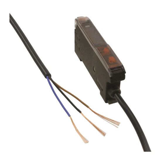
Digital Fiber Amplifier
E3X-DA-N
The Ultimate Fiber Amplifier for
Maximum Ease of Use and High
Performance
Be sure to read Safety Precautions
on page 23.
Features
Models with New Connector System
Reduces Wiring, Saves Space, and Makes
Maintenance Easier
First in the Industry Patent Pending
In Amplifiers with wire-saving connectors, the power supply is
distributed to 1-conductor slave connectors through a 3-
conductor master connector. This design has three major
advantages.
1. Wiring time is significantly reduced.
2. Relay connectors are unnecessary, so wiring takes up less
space and costs are reduced.
3. Storage and maintenance are simpler because it isn't
necessary to distinguish between master connector and
Slave Connectors on the Amplifier.
Simplified Connector Design
Up to 16 Amplifiers can
be connected.
Optical
communi-
cations
Master connector
http://www.ia.omron.com/
* UL certification including UL 991 testing and evaluation • Applicable standards: UL 3121-1
• Additional application testing and evaluations standards: UL 991 and SEMI S2-0200S
Power
supply pin
Slave connector
Super Digital Display with Auto Power
Control (APC) Circuit
The passage of time causes the intensity of the Sensor's light-
emitting LED elements to deteriorate, which may make stable
detection impossible.
The E3X-DA-N is the first series of Fiber Sensors to use an
Auto Power Control (APC) circuit. This achieves strict
detection by eliminating fluctuation in the digital value and is
ideal for subtle detection such as stable detection of liquid-
crystal glass.
Incident level
3000
Previous Digital
Threshold
Fiber Amplifiers
Incident level
3000
E3X-DA-N Series
Threshold
(c)Copyright OMRON Corporation 2007 All Rights Reserved.
UL991*
First in the Industry
Unstable detection
Time
Stable detection
Time
1
Advertisement
Table of Contents

Related Manuals for Omron E3X-DA-N series


Summary of Contents for Omron E3X-DA-N series
- Page 1 Up to 16 Amplifiers can Previous Digital Threshold be connected. Fiber Amplifiers Unstable detection Time Incident level 3000 E3X-DA-N Series Threshold Optical communi- cations Stable detection Power supply pin Master connector Slave connector Time http://www.ia.omron.com/ (c)Copyright OMRON Corporation 2007 All Rights Reserved.
- Page 2 Channel setting flash the Sensor head and section display the amplifier channels. Light intensity monitor Channel 5 Threshold Channel 4 Channel 3 Channel 2 Channel 1 Operation keys Battery monitor Optical communications Head http://www.ia.omron.com/ (c)Copyright OMRON Corporation 2007 All Rights Reserved.
-
Page 3: Ordering Information
Master E3X-CN11 Differential-output E3X-DA6D model* Slave E3X-CN12 ON/OFF output Water-resistant models XS3F-M421-40@-A E3X-DA14V E3X-DA44V (M8 connector) XS3F-M422-40@-A Master E3X-CN21 Twin-output models E3X-DA6TW E3X-DA8TW Slave E3X-CN22 * For details, refer to page 6. http://www.ia.omron.com/ (c)Copyright OMRON Corporation 2007 All Rights Reserved. - Page 4 Amplifiers (5 Units) 1 Master Connector 4 Slave Connectors Sensor I/O Connectors (Order Separately) Size Cable specifications Appearance Cable type Model XS3F-M421-402-A Straight XS3F-M421-405-A connector 4-wire Standard cable connection XS3F-M422-402-A L-shaped XS3F-M422-405-A connector http://www.ia.omron.com/ (c)Copyright OMRON Corporation 2007 All Rights Reserved.
- Page 5 ➜Refer to page 25. E3X-DA-N Series E39-L143 End Plate E3X-DA@V E39-L148 Appearance Model Quantity * When using a Through-beam Fiber Unit, order one Bracket for the Receiver and one for the Emitter. PFP-M http://www.ia.omron.com/ (c)Copyright OMRON Corporation 2007 All Rights Reserved.
- Page 6 Switching between normal/peak-hold/bottom-hold possible Display orientation Switching between normal/reverse possible Optical axis adjust- Optical axis adjustment possible (hyper-flashing function) ment Ambient illumination Incandescent lamp: 10,000 lx max. (receiver side) Sunlight: 20,000 lx max. http://www.ia.omron.com/ (c)Copyright OMRON Corporation 2007 All Rights Reserved.
- Page 7 Refer to Instruction Manual provided Amplifier and the adjacent Connector. with the Mobile Console for details. Housing Polybutylene terephthalate (PBT) Material Contacts Phosphor bronze/gold-plated nickel Weight (packed state) Approx. 55 g Approx. 25 g http://www.ia.omron.com/ (c)Copyright OMRON Corporation 2007 All Rights Reserved.
- Page 8 One-point teaching level can be varied from 1% to 50% in increments of 1% Operation indicator (orange), 7-segment digital incident level display (red), 7-segment digital detection level display Indicators (red) For other information, refer to the instruction manual supplied with the product. http://www.ia.omron.com/ (c)Copyright OMRON Corporation 2007 All Rights Reserved.
- Page 9 Super-long distance Standard Standard Super-high speed Distance X (mm) Distance −200 −50 −50 Distance X (mm) Standard −400 −100 X (m) High speed −100 −600 −150 Super-long distance Super-long distance −800 −200 −150 http://www.ia.omron.com/ (c)Copyright OMRON Corporation 2007 All Rights Reserved.
- Page 10 −150 Super-long distance −200 −200 Through-beam Through-beam E32-T16P E32-T16PR −50 −50 High speed Distance X (m) Distance X (m) −100 Standard −100 Standard −150 Super-high speed Super-long distance Super-long distance −150 −200 http://www.ia.omron.com/ (c)Copyright OMRON Corporation 2007 All Rights Reserved.
- Page 11 High speed Standard −5 Distance Distance −10 High speed −4 X (mm) Distance X (mm) −10 X (mm) −20 High speed −8 Standard −15 Super-long distance Super-long distance Super-long distance −30 −20 −12 http://www.ia.omron.com/ (c)Copyright OMRON Corporation 2007 All Rights Reserved.
- Page 12 X (mm) −40 X (mm) X (mm) −100 −1.0 High speed Standard Super-long −80 −150 −1.5 distance High speed Super-long distance −200 −2.0 −120 Limited Reflective E32-L25L Distance X (mm) −0.5 −1 http://www.ia.omron.com/ (c)Copyright OMRON Corporation 2007 All Rights Reserved.
- Page 13 −10 Super-long distance Super-high 0.4-mm-dia. Super-long −15 speed copper wire distance −20 Distance (mm) Distance X (mm) E3X-DA-N Monitor Output vs. Distance (Standard Mode) Through-beam Reflective E32-TC200 E32-DC200 Distance (mm) Distance (mm) http://www.ia.omron.com/ (c)Copyright OMRON Corporation 2007 All Rights Reserved.
- Page 14 Super-long distance −30 −60 Distance distance −40 Super-long distance X (mm) −40 −80 −50 For other information on Fiber Units, refer to the Fiber Sensors Best Selection Catalog (Cat. No. E353). http://www.ia.omron.com/ (c)Copyright OMRON Corporation 2007 All Rights Reserved.
- Page 15 Threshold 2 1000 Threshold 2 3000 Threshold 1 Time Time 1000 Threshold 2 Output 1 Output 1 Time Output 2 Output 2 Output 1 Output 2 Note: Output 2 is always OFF. http://www.ia.omron.com/ (c)Copyright OMRON Corporation 2007 All Rights Reserved.
- Page 16 Application cation pin No. Wire colors Brown Brown Power supply (+V) White Blue White Black Blue Power supply (0 V) XS3F-M421-402-A Black Output XS3F-M421-405-A XS3F-M422-402-A Note: Pin 2 is not used. XS3F-M422-405-A http://www.ia.omron.com/ (c)Copyright OMRON Corporation 2007 All Rights Reserved.
- Page 17 Application fication pin No. Wire colors Brown Brown Power supply (+V) White Blue White Black Blue Power supply (0 V) XS3F-M421-402-A Black Output XS3F-M421-405-A XS3F-M422-402-A Note: Pin 2 is not used. XS3F-M422-405-A http://www.ia.omron.com/ (c)Copyright OMRON Corporation 2007 All Rights Reserved.
- Page 18 Lock Button Level Display MODE Operation Indicator Channel-selection Switch ON when output is ON. Use to switch between channels 1 and 2. Mode Selector Use to select SET, ADJ, or RUN mode. http://www.ia.omron.com/ (c)Copyright OMRON Corporation 2007 All Rights Reserved.
- Page 19 The items displayed in ADJ mode vary with the display setting in RUN mode. RUN mode ADJ mode Digital incident level Digital threshold Digital percent Digital percent Analog value Analog value http://www.ia.omron.com/ (c)Copyright OMRON Corporation 2007 All Rights Reserved.
- Page 20 Alternates MODE Display orientation setting Reversing display TEACH Standard (factory-set) Alternates TEACH TEACH Reverse Note: It is not possible to set an lower limit TEACH that is lower than the lower limit. http://www.ia.omron.com/ (c)Copyright OMRON Corporation 2007 All Rights Reserved.
- Page 21 • If channel 1 is set to D-ON, output turns OFF TEACH when the incident level is between the thresholds. The result is output to control output 1. (Control output 2 is always OFF.) http://www.ia.omron.com/ (c)Copyright OMRON Corporation 2007 All Rights Reserved.
- Page 22 Note: There is no operating mode selector for twin-output models. level display is lit. The level display will display the digital incident level later. (The red level (Green) display will flash if a teaching error occurs.) Set to RUN mode. http://www.ia.omron.com/ (c)Copyright OMRON Corporation 2007 All Rights Reserved.
-
Page 23: Safety Precautions
(i.e., increase the threshold) to perform stable detection. EEPROM Writing Error If the data is not written to the EEPROM correctly due to a power failure during teaching or static-electric noise, repeat the whole teaching procedure. http://www.ia.omron.com/ (c)Copyright OMRON Corporation 2007 All Rights Reserved. - Page 24 Depending on how it is mounted, an Amplifier may move during operation. In this case, use an End Plate. Before mounting an End Plate, remove the clip from the master Amplifier using a nipper or similar tool. Clip http://www.ia.omron.com/ (c)Copyright OMRON Corporation 2007 All Rights Reserved.
- Page 25 Accessories Operating Instructions Sticker E39-Y1 • Attach near the Sensor. • 1 English and 1 Japanese sticker per set • Material: Front side: Paper, Reverse side: Adhesive tape Japanese Sticker English Sticker http://www.ia.omron.com/ (c)Copyright OMRON Corporation 2007 All Rights Reserved.
- Page 26 Two, M3 *1. The Mounting Bracket can also be used on side A. 4-dia. vinyl-insulated round cable with 3 conductors (Conductor cross section: 0.2 mm Insulation diameter: 1.1 mm). Standard length: 2 m. http://www.ia.omron.com/ (c)Copyright OMRON Corporation 2007 All Rights Reserved.
- Page 27 E3X-CN12: 2.6 dia. 67.5 E3X-CN21: 4.0 dia. E3X-CN22: 4.0 dia. 64.3 64.3 E3X-CN02: With no cable E3X-CN02: With no cable 31.5 31.5 17.45 12.95 12.95 11.55 1.8 5.1 3.9 1.8 5.1 3.9 http://www.ia.omron.com/ (c)Copyright OMRON Corporation 2007 All Rights Reserved.
- Page 28 Dimensions with Master Connector Connected Dimensions with Slave Connector Connected 67.5 67.5 64.3 64.3 E3X-CN21: E3X-CN22: 4.0 dia. 4.0 dia. 31.5 31.5 17.45 12.95 12.95 11.55 1.8 5.1 3.9 1.8 5.1 3.9 http://www.ia.omron.com/ (c)Copyright OMRON Corporation 2007 All Rights Reserved.
- Page 29 Output Mode display plunger communications indicator 51.3 position Channel buttons Teaching Escape button button Enter button Power supply button Mode button Function button Battery indicators Accessories (Order Separately) Mounting Brackets End Plate http://www.ia.omron.com/ (c)Copyright OMRON Corporation 2007 All Rights Reserved.
-
Page 30: General Precautions
(2) Do not use the Sensor in environments where the cables may become immersed in oil or other liquids or where liquids may penetrate the Sensor. Doing so may result in damage from burning and fire, particularly if the liquid is flammable. http://www.ia.omron.com/ (c)Copyright OMRON Corporation 2007 All Rights Reserved. -
Page 31: Precautions For Correct Use
Receiver. Sensor sensing distance.) (Light may enter even if the Sensors are separated by Sensor Sensor more than the sensing distance.) θ θ Adjust the Lowering the sensitivity will generally help. sensitivity. http://www.ia.omron.com/ (c)Copyright OMRON Corporation 2007 All Rights Reserved. - Page 32 Repeated Bending other terminals. Normally, the Sensor cable should not be bent repeatedly. (For bending-resistant cable, see Attachment to Moving Parts page C-4.) http://www.ia.omron.com/ (c)Copyright OMRON Corporation 2007 All Rights Reserved.
- Page 33 Approx. 13,000 times Approx. 500,000 times The testing conditions of the standard cable and robot cable are different. Refer to the values in the above table to check bend-resistant performance under actual working conditions. http://www.ia.omron.com/ (c)Copyright OMRON Corporation 2007 All Rights Reserved.
- Page 34 Locked position Note:1.To maintain the fiber characteristics, make sure that the lock is released before removing the fibers. 2. Lock and unlock the fibers at an ambient temperature of − 10 to 40°C. http://www.ia.omron.com/ (c)Copyright OMRON Corporation 2007 All Rights Reserved.
- Page 35 (height) detection data, and selection list for specifications. Cleaning • Keep organic solvents away from the Sensor. Organic solvents will dissolve the surface. • Use a soft, dry cloth to clean the Sensor. http://www.ia.omron.com/ (c)Copyright OMRON Corporation 2007 All Rights Reserved.
- Page 36 Warranty and Limitations of Liability WARRANTY OMRON's exclusive warranty is that the products are free from defects in materials and workmanship for a period of one year (or other period if specifi ed) from date of sale by OMRON. OMRON MAKES NO WARRANTY OR REPRESENTATION, EXPRESS OR IMPLIED, REGARDING NON-INFRINGEMENT, MERCHANTABILITY, OR FITNESS FOR PARTICULAR PURPOSE OF THE PRODUCTS.
- Page 37 Mouser Electronics Authorized Distributor Click to View Pricing, Inventory, Delivery & Lifecycle Information: Omron E3X-CN21 E3X-CN22 E3X-CN11 E3X-CN12 E3X-DA21-N E3X-DA41-N E3X-DA51-N E3X-MC11 E3X-MC11-C1 E3X-MC11-H1...
Need help?
Do you have a question about the E3X-DA-N series and is the answer not in the manual?
Questions and answers