Doosan M0609 User Manual
Hide thumbs
Also See for M0609:
- Programming manual (392 pages) ,
- User manual (253 pages) ,
- Reference manual (202 pages)
Table of Contents
Advertisement
Quick Links
Advertisement
Table of Contents

Related Manuals for Doosan M0609


Summary of Contents for Doosan M0609
-
Page 2: Table Of Contents
3.2.1 Disengaging Packaging Pose ..........................19 3.2.2 3.3 Robot Mode and Status ................... 20 Manual Mode ................................20 3.3.1 Auto Mode ..................................21 3.3.2 Status and Flange LED Color for Each Mode ....................21 3.3.3 Doosan Robotics User Manual v1.7... - Page 3 3.4 Robot Setting ....................22 3.5 Robot Safety Setting ..................22 Safety Limit Setting ..............................22 3.5.1 Work Area Setting ..............................22 3.5.2 4. Manual Robot Operation ............24 4.1 Jog Operation....................24 4.2 Hand-Guiding Operation ................. 24 Teach Pendant Hand-Guiding Button ......................... 24 4.2.1 Cockpit Button ................................
- Page 4 8. Task Builder ................74 8.1 Task Management .................... 74 Create New Task ............................... 74 8.1.1 Template ..................................74 8.1.2 Save Task ..................................75 8.1.3 Save Task As ................................75 8.1.4 8.1.5 Editing Workcell Items ............................. 75 Doosan Robotics User Manual v1.7...
- Page 5 Save Task on External Storage Device ......................76 8.1.6 Load Saved Task ............................... 76 8.1.7 Delete Saved Task ..............................76 8.1.8 Import Task on External Storage Device ......................76 8.1.9 8.2 Task Builder Command .................. 77 8.3 Deprecated Skill Command ................79 8.4 Edit Task ......................
- Page 6 10.4 Setting up the back drive operation mode..........110 10.5 Safety Recovery Mode................... 111 10.5.1 Setting up the software recovery mode ......................111 10.5.2 Setting up the packaging mode ........................... 112 11. Jog Function ................114 11.1 Jog screen ....................... 115 Doosan Robotics User Manual v1.7...
- Page 7 11.1.1 Running jog mode on a joint basis ........................116 11.1.2 Running jog mode based on the robot base ....................117 11.1.3 Execute based on World Coordinates ......................118 11.1.4 Running jog mode based on the tool ......................... 119 11.2 Move screen ....................120 11.2.1 Moving the robot by specifying an angle ......................
- Page 8 12.9 Check Log ......................138 12.9.1 System Log ................................138 12.9.2 Extract Log .................................. 138 12.10 Factory Reset ..................138 12.10.1 Delete Log .................................. 138 12.11 Screen Saver Mode Setting ............... 138 12.12 Idle Servo Off ..................139 Doosan Robotics User Manual v1.7...
-
Page 9: Preface
Copyright Doosan Robotics has copyright and intellectual property rights to all content and all designs shown in this manual. Therefore, any use, copying, or dissemination of them without written permission from Doosan Robotics is prohibited. -
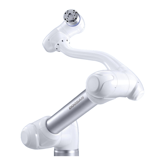
Page 10: Product Introduction
Product Introduction Robot Overview 1.1.1 Name of parts Part Part Base Link2 Link1 Tool Flange Doosan Robotics User Manual v1.7... -
Page 11: Main Function
1.1.2 Main function Part Description Cockpit (teach The button used to perform direct teaching (optional) button) The area on which a tool is mounted Tool Flange Displays the status of the robot. . For more information about robot status, refer to the “3.3.3 Status and Flange LED Color for Each Flange LED Mode... -
Page 12: Control Box Overview
Turns on/off the main power of the control box Power switch The terminal through which the robot’s cable is connected to the Robot cable connection terminal control box The terminal to which the control box’s power cord is attached Power terminal Doosan Robotics User Manual v1.7... -
Page 13: Teach Pendant Overview
Teach Pendant Overview Part Description Turns on/off the main power of the teach pendant. Power button The LED color changes according to the power status of the teach Power LED pendant. In the event of an emergency, you can stop the robot by pressing this Emergency stop button. -
Page 14: Safety
• Never put your fingers into the space behind the control box’s inner bracket. Otherwise, you may sustain electric shock or injury due to the wiring existing in the space. • Never modify the robot. Doosan Robotics will not be held responsible for any consequences resulting from arbitrary modification of the robot. - Page 15 • It is recommended that you test the robot program by designating a temporary waypoint outside the operating radius of the other apparatus. Doosan Robotics will not be held responsible for any damage to the robot or other equipment caused by programming errors or robot failures.
-
Page 16: Types Of Stop Modes For Safety
• Emergency stop must not be used as a risk reduction method, but as a secondary protection device. • If additional Emergency Stop buttons are needed, an application risk assessment must be performed. The Emergency Stop button must comply with IEC 60947-5-5. Doosan Robotics User Manual v1.7... -
Page 17: Other Safety Functions
Other Safety Functions The system offers Safety Recovery Mode and Zero-Gravity Motion for user safety and robot recovery. • Safety Recovery Mode: If there is an error with a continuing safety violation or if a robot is to be packed, the user can use Safety Recovery Mode to configure the position and angle of the robot. For more information about Safety Recovery Mode, refer to “... -
Page 18: Starting Up The Robot
Starting Up the Robot System Power-Up Press and hold down the power button in the upper left corner of the teach pendant. • Then, the power to system essentials such as the robot, control box, and teach pendant is turned •... -
Page 19: Booting And Disengaging Packing Position
Booting and Disengaging Packing Position 3.2.1 System Booting After the system is powered on, the system boots up. When booting is complete, the system application is displayed on the teach pendant. For more information about the system application, refer to “5 System Operation Program Outline.” Note ... -
Page 20: Robot Mode And Status
Task Builder and Task Writer, and if the robot cannot be operated normally for reasons such as the robot exceeding the safety threshold, the Recovery function can be performed to restore normal operation. Doosan Robotics User Manual v1.7... -
Page 21: Auto Mode
3.3.2 Auto Mode This is the mode in which the robot operates without direct user control. The robot will execute the programmed task or predefined sequence with a simple operation command and without additional user input. Task Builder or Task Writer can verify the programed task in virtual mode, execute it in actual operation, and perform robot tool weight and auto weight center measurement functions. -
Page 22: Robot Setting
Setting. For more information about the work space setting, refer to “7.4.9 Robot Work Space Setting.” • Collaborative Work Space: This is the work space where the operator and robot can work Doosan Robotics User Manual v1.7... - Page 23 together, and the task speed and joint speed can be decelerated by configuring a deceleration rate in the collaborative work space. For more information about the collaborative common work space, refer to “7.4.5 Collaborative Work Space Setting ” • Protection Section: If an object breaches the section set as the protection section, the robot stops according to the Safety Stop mode setting.
-
Page 24: Manual Robot Operation
However, if the robot is set to the Hand-guiding Ready state with the Hand Guide command of the Task Writer, the button can be used even in Automatic mode. 4.2.2 Cockpit Button The user can change the robot pose while holding the Hand-guiding button or custom button on the cockpit. Doosan Robotics User Manual v1.7... - Page 25 번호 항목 설명 Enables you to freely change the pose of the robot in any Hand-guiding button direction. Enables you to change the pose of the robot by entering your desired pose according to the fixed condition corresponding to its assigned mode. ...
-
Page 26: Robot Teaching And Execution
Robot Teaching and Execution In order to use the robot in the user’s process, the robot space, end effector, machine tools and peripherals must be configured in the Workcell Manager first. When Workcell Manager setting is Doosan Robotics User Manual v1.7... - Page 27 Manager, allowing the user to easily create and execute task programs. The Task Writer uses DRL (Doosan Robot Language) to create and execute programs suited for the user’s process, and it also features a Custom Code function where the user can load and execute task programs created by referring to the Programming Manual.
-
Page 28: System Operation Program Outline
System Operation Program Outline The UI of the system operation program consists of the following: Area Description This area displays the name of the task currently running and the Status display current operating status of the robot. area When you perform a task using the robot, you enter and change settings in this area. -
Page 29: Work Screen Area
Item Description Tap the "menu" button to create a new task, or save or load a task currently being edited. The functions displayed when the menu Menu button is tapped vary according to the screen displayed. The name of the task currently being executed is displayed. Task Name Tool Setting It runs the Tool Setting pop-up. - Page 30 Automatic Mode: This is the mode where the robot is operated automatically according to the user’s task. Main menu buttons other than the Status and Power buttons are disabled. Stopping the current task will enable all buttons. Doosan Robotics User Manual v1.7...
-
Page 31: Home Screen Overview
Home Screen Overview Information about the current task status and task, and work progress graph are displayed. Item Description The total number of lines of the task program is displayed. Tapping the number indicating the program line will move to the Task Builder or Task Writer. -
Page 32: Task Execution And Stopping
Log messages Displays the task's log information. Displays the number of times the task is repeatedly executed, the Run/stop task playback time, and the average execution time. Tapping Stop button stops the running task. Doosan Robotics User Manual v1.7... -
Page 33: Opening And Running A Saved Task
Opening and running a saved task You can load a recently executed task or a task stored in the system on the Home screen. On the system's default screen, tap the Menu button( Select Open from the menu screen. A list of tasks stored in the system appears on the right pane. -
Page 34: Tool Setting
Workcell Manager screen, so the tool center point, weight and shape of the end effector to be used must be set in Tool Settings of the tool. Item Description Tool Setting It runs the Tool Setting pop-up. Button Select the Tool Setting button. Doosan Robotics User Manual v1.7... - Page 35 Select the desired Workcell item from the Tool Center Point, Weight or Tool Shape Press the Setting button to save the tool center point, weight or shape of the corresponding Workcell item. Note The robot’s tool center point and tool weight can be set to default where no input is made by pressing the Reset button.
-
Page 36: Workcell Manager
Workcell Manager What is a Workcell Item? Workcell Item refers to the robot and all peripherals used together with the robot. Workcell items can be configured in the Workcell Manager screen before use. Also, the Workcell Manager can set commands for peripherals and can configure commands for the robot to perform certain patterns and actions. - Page 37 Item Description Screw drivers Gluing tools Deburring tools Airblow nozzles Polishing tools Custom tools Displays a list of equipment corresponding to the robot. Press Machine Machine Turning center Injection molding machine Displays a list of peripherals connected to the robot.
-
Page 38: Add Workcell Item
On this screen, select your desired workcell’s type and category and tap the Select button, and then you are directed to the corresponding workcell setup pane. Doosan Robotics User Manual v1.7... -
Page 39: Deprecated Workcell Item
Deprecated Workcell Item Workcell Items are managed in two states: Normal, where new items can be registered, and Deprecated, where maintenance is no longer possible. Workcell Items can be updated due to increased usability and additional motion improvements. If a Workcell Item is updated, the existing Workcell Item becomes deprecated, and it cannot be added or edited. -
Page 40: Robot Setting
Robot Setting The robot’s Workcell Setup screen is composed as follows: Item Description Enter workcell Enter a name for the workcell. name Displays a simulation of the workcell’s operating space. Simulation screen Doosan Robotics User Manual v1.7... - Page 41 Item Description You can view all registered workcells, including those in other Show all work environments. Checking the checkbox enables the view all feature. Unchecking the checkbox gets the feature disabled again. Displays the simulation in a larger image. Tapping the Thumbnail view ( ) button on the enlarged screen switches back to the View larger (...
-
Page 42: World Coordinatessetting
Task Builder and Task Writer. To set World Coordinates, tap the Add button on the Robot Workcell and select Robot>World Coordinates. Tap the Edit button at the top. Doosan Robotics User Manual v1.7... - Page 43 Please refer to the figure depicting the relationship between the World Coordinate and Base Coordinate, as well as related precautions. Warning When changing the relationship between World and Base coordinates, the teaching point of World Coordinates or user coordinates based on World Coordinates can change. Change is only recommended when the actual relationship between World Coordinates and Base Coordinates are changed.
- Page 44 User programs created using the Task Builder and Task Writer after applying the installation inclination in SW versions earlier than GF020400 must set World Coordinates with the installation inclination applied when updating to SW versions later than GF020400 and convert Doosan Robotics User Manual v1.7...
-
Page 45: Robot Limits Setting
all Base Coordinates into World Coordinates within the user program in order to properly use existing teaching points. 7.4.2 Robot Limits Setting It sets the safety limits of safety monitoring functions. Note The limit and initial safety settings may vary according to the robot lineup. Safety limits is the condition where the safety rated monitoring function triggers the stop function. - Page 46 Speed. The Joint Speed Limits setting screen layout is composed of the following: Item Description Joint Speed It can limit the speed of each joint. Default Value It resets the Joint Speed Limits settings to default values. Doosan Robotics User Manual v1.7...
- Page 47 Item Description Confirm It saves the current Workcell.
-
Page 48: Safety I/O Setting
STO Stop Mode. To set the Safety I/O, go to the Robot Workcell and select Robot>Safety I/O. • Safety Input Setting Doosan Robotics User Manual v1.7... - Page 49 • High: Normal operation Safe Torque Off (L) Low: Immediately cuts the motor power and engages the brakes to force the robot to stop. High: Normal operation Emergency Stop (L) Low: It stops the robot according to the Stop Mode of the Emergency Stop of the Safety Stop Mode.
- Page 50 High: The robot is currently not in Auto Mode Auto Mode (L) Low: The robot is currently in Auto Mode Doosan Robotics User Manual v1.7...
- Page 51 Emergency Stop (L) It is used to notify the user of a situation where emergency stop is required, such as when the Emergency Stop Button is pressed, external Emergency Button is pressed, or self- diagnosis defect is detected. High: Normal operation Low: Emergency stop required ...
-
Page 52: Safety Stop Modes Setting
Stop Mode. • Momentum Limit Violation: It sets the Stop Mode when the robot momentum exceeds the set limit. • Mechanical Power Limit Violation: It sets the Stop Mode when the mechanical power of the Doosan Robotics User Manual v1.7... -
Page 53: Setting The Robot's Installation Pose
robot exceeds the set limit. 7.4.5 Setting the robot’s installation pose The robot can be installed at any angle. To configure the robot installation pose, tap the "Add" button on the Robot Workcell and select Robot>Robot Installation Pose. The robot installation pose can be entered manually or calculated automatically. -
Page 54: Tool Shape Setting
Tool shape can be set by adding Cuboid, Sphere, and Capsule shapes. Select a shape that matches the tool and tap the OK button. 7.4.7 Tool Weight Setting To configure the robot tool weight, tap the "Add" button on the Robot Workcell and select Robot>Tool Weight. Doosan Robotics User Manual v1.7... - Page 55 Automatic Tool Weight Measurement: Select an automatic motion calculation method. All Motion: All joints are used to measure tool weight. 4, 5, 6 Motion: Joints 4, 5 and 6 are used to measure tool weight. Enable the checkbox of the parameter (weight, center of gravity) to estimate. ...
-
Page 56: Robot Operation Environment Types
Sets the robot work environment in the form of a cylinder. Enter the point at a radius distance, point of the upper plane and point of the lower plane of the cylinder, and tap the "Save Pose" button. Cylinder Doosan Robotics User Manual v1.7... - Page 57 항목 설명 Sets the robot work environment in the form of a multi-angular prism. Enter the point of the upper plane and point of the lower plane of the multi-angular prism, and tap the "Save Pose" button. Enter points of the lower plane (min. three points / max. 10 points) and tap the "Save Pose"...
-
Page 58: Robot Work Space Setting
) button to enable Plane 2. Tap the "toggle" ( ) button of Point 1 of area setting. In the space consisting of planes, place the robot’s TCP in the area to be configured as the collaborative work space. Doosan Robotics User Manual v1.7... -
Page 59: Protection Section Setting
Tap the "Save Pose" button of Area Setting Point 1 to enter the position value. If the robot is stopped by Safety Stop Mode SS2 or RS1 within a collaborative workspace, the work can be resumed with Nudge input. To enable Nudge input, tap the Nudge toggle ( button. -
Page 60: Disable Collision Detection Section Setting
When the low signal is input to the selected port, the collision-detection mute zone is disabled and a collision detection check is performed Press the Confirm button to save the workcell. Doosan Robotics User Manual v1.7... -
Page 61: Tool Direction Change Limit Section Setting
7.4.13 Tool Direction Change Limit Section Setting To configure the tool direction change limit space, tap the "Add" button on the Robot Workcell and select Tool Direction Change Limit Space>Cuboid, Cylinder, Multi-angular Prism, Sphere or Tilted Cuboid type. The Safety Password is required during setup. Enter the Workcell Name in the Workcell Name field on the top of the Workcell Setting screen. - Page 62 : Selects the output signal port of the workcell. Test: Checks the status of the input signal. If the signal has been inputted normally, it is displayed in green. Delete Deletes the workcell you are currently configuring. Doosan Robotics User Manual v1.7...
- Page 63 Section Name Description Confirm Saves the settings of the workcell. Tools include a screwdriver, gluing tool, deburring tool, and polish and airblow nozzle, and there is also a custom tool setting function to allow the use of other user tools. Configuring tool settings is similar to that of gripper settings.
-
Page 64: End Effector I/O Signal Setting
Connect the end effector's port to the robot flange or control box. Enter the number of the connected port in the port number field for input signal and for output signal. Tap the Confirm button Doosan Robotics User Manual v1.7... -
Page 65: Testing The I/O Of An End Effactor
7.5.3 Testing the I/O of an end effactor Test the operating status of the workcells of the connected end effector: Tap the Edit button for the end effector added. On the end effector workcell setup screen, tap the Operating Status button for the output signal you want to test. -
Page 66: Tool Rotation Angle (A, B, C) Within Tool Center Point Setting
• Coordinate axis of “TCP Coordinate” (X,Y,Z): The coordinate axis is defined at the end of the tool installed on the end of the flange or working point. The rotation angle of the “TCP Coordinate” is defined based on the “Flange Coordinate” in the order of 1) to 3) of the following: Doosan Robotics User Manual v1.7... - Page 67 Z’ 1) Rotated by A 2) Rotated by B Z” along Axis - Z along Axis - Y X’ Y” Y’ X” Flange Coord. 3) Rotated by C along Axis - Z” TCP Coord. 1) Rotate A degrees along the z axis of the Flange Coordinate 2) Rotate B degrees along the y’...
-
Page 68: Tool Center Point Setting Based On Other End Effeactors
Configure the tool Z axis rotation angle of the configuring end effector and base end effector. Click the Auto Calculate button on the bottom, check whether the calculated tool center point is automatically entered, and click Confirm to complete. Doosan Robotics User Manual v1.7... -
Page 69: Machine Tool Setting
Note The configuring end effector and base end effector must be symmetrical on the tool Z axis. Machine Tool Setting Machine tools are the main work device that interacts with the robot, and the machine tools that can be registered in the Workcell Manager are as follows: Category Type... -
Page 70: Peripheral Setting
Externally installed Conveyor Operation Setting Tracker The following is the setting screen for the Pallet. This example will be used as the basis for explanation. For more information about each feeder setting, refer to the separate manuals provided. Doosan Robotics User Manual v1.7... - Page 71 Section Name Description Pallet rows/columns Enter the number of rows and columns for the pallet. Pallet pattern Select the pattern in which the robot will move on the pallet. Saves the coordinate corresponding to the robot’s current Get Pose position. Moves the robot to the coordinates entered at the bottom of the screen.
- Page 72 Move the robot TCP to position 2 in the pattern guide and tap the Get Pose button. Enter the coordinates of position 3 in the pattern guide in the same way. Tap the Confirm button. Doosan Robotics User Manual v1.7...
-
Page 73: Others
7.7.1 Others The others category includes Button. The others category settings are similar to that of the gripper settings. For more information about the others category, refer to the separate manuals provided. 7.7.2 Vision For more information about vision setting, refer to the Reference Manual provided separately. -
Page 74: Task Builder
Task Builder After registering and configuring all Workcell items in the Workcell Manager, the program to execute the robot task must be created using commands or skills. With the Task Builder, the user can create a new task, enter skills or commands, or create tasks using templates recommended by the system. -
Page 75: Save Task
Enter the name of the new task program in the File Name field. Tap the "OK" button. When a new task is created using a template, the task edit screen is displayed. For more information about task edit, refer to “8.4 Edit Task.” 8.1.3 Save Task To save an edited task, tap the "Menu"... -
Page 76: Save Task On External Storage Device
"Menu" button and tap "Open". Select a task to delete from the file list and tap the "Delete" button. 8.1.9 Import Task on External Storage Device To import a task saved on an external storage device, follow these steps: Doosan Robotics User Manual v1.7... -
Page 77: Task Builder Command
Connect the external storage device with the task file to the USB slot of the control box. Select "Import" on the Taskwriter main screen. Tap the "Search" button. When the Search File window appears, select the file to import and tap the "OK" button. Tap the "Import"... - Page 78 This is used to execute the defined thread. Kill Thread This is used to end thread execution. Sub Task This is the command to define a thread within the task. Call Sub Task This is the command to execute the defined subtask. Doosan Robotics User Manual v1.7...
-
Page 79: Deprecated Skill Command
Wait This is used to temporarily stop task execution. This is used to receive user input and save it in a variable during User Input task execution. • Force Control Command: The force of the robot can be controlled during task execution. Compliance This is used to control Compliance during task execution. -
Page 80: Edit Task
Safe stop: Indicates that the robot's operation has been stopped due to an error or safety problem. Cease your task and check the status of the robot when the robot is in this status. Emergency stop: Indicates that the robot’s operation has been stopped by the emergency safety button. ". Doosan Robotics User Manual v1.7... -
Page 81: Edit Task Screen Configuration
8.4.1 Edit Task Screen Configuration Task Builder’s edit screen is composed as follows: Item Description Displays the command editing tools. Multi- select: Select multiple commands Copy: Copies the command. Cut: Cuts the command. Command edit Delete: Deletes the command. tools (CTR) ... -
Page 82: Add Command
Select a command to delete and tap the "Delete" button in the command edit tools. When a confirmation window appears, tap the "OK" button. 8.4.4 Paste command To copy/cut and paste a command to the task list, follow these steps: Select command to copy or cut. Doosan Robotics User Manual v1.7... -
Page 83: Setting And Applying Command Property
Tap the "Copy" or "Cut" button on the command edit tool. Select the location to paste the command. The copied/cut command is added to the next line of the selected location. Tap the "Paste" button on the command edit tool. Setting and Applying Command Property Tap a command list added to the task list to configure the properties of the command. -
Page 84: Velocity Setting
If the radius is set to 0, the motion blending function does not activate. So, if the robot reaches the target point of the current command, it stops and then moves to the target point of the next motion command. Doosan Robotics User Manual v1.7... - Page 85 Overlap: When the robot reaches the set radius centering the target point of the motion command, it retains the velocity of the current command and moves to the target point of the next command. Override: When the robot reaches the set radius centering the target point of the motion command, it immediately reduces the velocity of the current command and moves to the target point of the next command.
-
Page 86: Multi-Segment (Waypoint) Setting
Either use the jog function or perform direct teaching to move the tool to the desired position. Tap the "Save Pose" button in segment properties to save the robot tool position. Repeat steps 1-3 to add segments. Doosan Robotics User Manual v1.7... -
Page 87: Skill Command Property Setting
Skill Command Property Setting 8.7.1 Understanding Basic Principles of Skill Commands Skill commands are based on a few operation patterns. For a robot to begin operation, the weight and tool center point (TCP) of the tool equipped on the robot must be configured, and the basic operation pattern of a skill command is to have an approach pose that is perpendicular to the action pose. - Page 88 Move to Retract Pose: This is the point to pick up the workpiece and safely move to another point. It is the -Z direction from the Approach Pose, and a different direction can also be selected. The Retract Distance entered is automatically calculated for the Action Pose and moves to the corresponding point. Doosan Robotics User Manual v1.7...
- Page 89 Move to Action Start Pose: If the End Effector execution target does not end with a single motion, there may be an intermediate point and an end point, and the Action Start Pose is the point where the work starts. (i.e. Door Open Skill - Start Pose, Screw Drive Skill – Start Pose) Move to Action End Pose: If the End Effector execution target does not end with a single motion, there may be an intermediate point and an end point, and the Action End Pose is the point where the work ends.
-
Page 90: Compliance Control And Contact Check
With the Compliance Control and Contact Check functions, which is the unique force control technology of Doosan Robotics, it is possible to easily perform teaching without repeated operation for accurate point designation, since it allows position deviation within an allowance range between the workpiece and surrounding items during robot operation. -
Page 91: Skill Command Work Point Setting With Cockpit Buttons
8.7.3 Skill Command Work Point Setting with Cockpit Buttons Cockpit buttons can be used to configure the action pose. For example, with the Pick skill command: Add a skill command from the Task Builder and tap the added skill command. Perform direct teaching to the skill’s action pose to move the robot. -
Page 92: Virtual Mode Screen
Sets viewpoints with a robot model as a control point. It is a slider control which sets the speed of the robot operation in a Speed slider real or a virtual mode. Stop button Stops the current task. Doosan Robotics User Manual v1.7... -
Page 93: Real Mode Screen: End Effactor Information Tab
Item Description Execute/pause Executes or pauses the task in the task list. toggle button Execution Time Displays the amount of time spent executing each command / skill. 8.8.2 Real mode screen: End Effactor Information tab The real mode screen(End Effactor Information tab) of the task builder is configured as follows: Item Description Sets the robot test play mode. -
Page 94: Real Mode Screen: I/O Information Tab
It is recommended to test the robot program by designating temporary waypoints outside another machine’s work space. Doosan Robotics will not be held accountable for damages that occur due to programming error or robot malfunctioning, as well as damage to the equipment. - Page 95 Item Description Sets the robot test play mode. Real mode ( Real mode: Operates an actual robot to test the task in the task list. Virtual mode: Uses a simulator screen to test the task in the task list. Total time Displays the total time elapsed after the task execution.
- Page 96 Stop button Stops the current task. Execute/pause Executes or pauses the task in the task list. toggle button Execution Time Displays the amount of time spent executing that command / skill. Doosan Robotics User Manual v1.7...
-
Page 97: Execute Task
8.8.4 Execute Task It is possible to test the task being created by executing it. To execute a task, follow these steps: Select the Play tab. Tap the Real mode ( ) button. Drag the speed slider bar to set the speed of the robot. Run the task by tapping ... -
Page 98: Task Writer
The Task Writer is intended for advanced users familiar with program coding. It allows complex motions that cannot be executed with basic commands to be created using DRL (Doosan Robot Language) and Custom Code, which allows the user to load and execute programs created or saved on an external storage device. -
Page 99: Save Task On External Storage Device
When save is complete, the Save Complete window appears. 9.1.4 Save Task on External Storage Device To save an opened task as on an external storage device, follow these steps: Connect an external storage device to the USB slot of the control box. ... -
Page 100: Import Task On External Storage Device
Connect the external storage device with the task file to the USB slot of the control box. Tap "Export" in the main screen of Task Writer. The export popup window appears. Select the external drive to export the task and tap the "OK" button. Doosan Robotics User Manual v1.7... - Page 101 The Save As popup window appears. Enter the task name in the popup window and tap the "OK" button.
-
Page 102: Edit Task Program
Thread is added, a command can be added below the Thread. Motion commands cannot be added to a Thread. Task Writer Command The commands available in the Task Writer are Motion Commands, Flow Control and Other Doosan Robotics User Manual v1.7... - Page 103 Commands, and Advanced Commands. • Motion Command: These are commands used to adjust or change the robot pose. Move J This is the command to move the robot to the target joint coordinate. This is the command to move the robot along a straight line to the Move L target work space coordinate.
- Page 104 This is used to measure the weight during task execution and save Weight Measure it in a variable. This is used to temporarily stop the robot after the previous Wait Motion motion command is complete. Doosan Robotics User Manual v1.7...
-
Page 105: Setting And Applying Command Property
• Advanced Commands: There is a command to execute hand guiding. Hand Guide This is used to execute direct teaching during task execution. This is used to delay task execution until Nudge (applying force to Nudge the robot) input. Setting and Applying Command Property Configuring and applying the commands in the Task Writer are identical to those of the Task Builder. - Page 106 Toggle Button the Restart button. Pause Button Temporarily pauses the current task execution.. Stop Button Suspends the current task. Step by Step Executes one command at a time while the task is paused. Doosan Robotics User Manual v1.7...
-
Page 107: Monitoring And Testing
10. Monitoring and Testing To check or test the I/O information, tap the "Status" button in the main menu. The "Status" window allows you to check the I/O information of devices connected to the control box and flange, and the Zero-Gravity Motion mode and Safety Recovery function can be executed. The Status window is a popup window, so it is possible to tap the "Status"... -
Page 108: Check I/O Status
10.2.2 Checking the analog input of the control box Select the item you want to check from the drop-down list in the control box analog input area. The analog input information relevant to the selected item appears on the screen. Note Doosan Robotics User Manual v1.7... -
Page 109: Setting Up The Digital Output Of The Control Box/Flange
You cannot set a value for analog input in the status pane. 10.2.3 Setting up the digital output of the control box/flange Check the port number of the device connected to the control box or flange. Press the On/Off icon corresponding to the port number to activate or deactivate digital output. -
Page 110: Setting Up The Back Drive Operation Mode
Power button on the top of the teach pendant. Tap the Power button again to turn the system back on. The breakdown status is cleared, and you can proceed with normal operation again. Doosan Robotics User Manual v1.7... -
Page 111: Safety Recovery Mode
Note When moving the position of each joint to the robot’s normal operating radius, please move one joint at a time. When you have run the back drive operation mode, you can resume operation only after rebooting the robot. 10.5 Safety Recovery Mode If the teach pendant program fails, or when you want to package the robot, you can set the robot at... -
Page 112: Setting Up The Packaging Mode
To configure the packaging mode, follow these steps: In the status pane, tap the Safe Recovery button. In the Safe Recovery screen pane, select the Pack/Unpack tab. On the packaging mode screen, enable the Package Mode toggle button. Doosan Robotics User Manual v1.7... - Page 113 Long press the Pack button. The robot moves automatically with the specified packaging pose. To undo the packaging pose, long press the Unpack button and disable the Package Mode toggle button.
-
Page 114: Jog Function
11. Jog Function In Jog mode, the user can navigated the entire work space or set the operation space the user configured as the robot operation space. The movement angle of each axis can be limited according to the selected operation space and joint angle limit of the safety setting. To use the jog function, tap the "Jog"... -
Page 115: Jog Screen
11.1 Jog screen It is possible to navigate based on the current robot position on the jog screen. Item Description It configures the joint as the reference coordinate for jog mode. Each reference coordinate can be entered differently for each robot joint (J1, Joint J1, J2, J3, J4, J5, J6). -
Page 116: Running Jog Mode On A Joint Basis
11.1.1 Running jog mode on a joint basis How to adjust the robot’s angles on a joint basis: Go to the Jog screen and tap the Joint tab. Select the axis whose angle you want to adjust (J1 to J6). Doosan Robotics User Manual v1.7... -
Page 117: Running Jog Mode Based On The Robot Base
Adjust the angle of the axis by holding down the direction buttons ( Note Safety zones are not applied in virtual mode. 11.1.2 Running jog mode based on the robot base How to move the robot based on its base: Go to the Jog screen and tap the Task tab. -
Page 118: Execute Based On World Coordinates
Move your desired axis by holding down the direction buttons ( Note Safety zones are not applied in virtual mode. 11.1.3 Execute based on World Coordinates To move the robot based on World Coordinates, follow these steps: Select the Task tab from the Jog screen. Doosan Robotics User Manual v1.7... -
Page 119: Running Jog Mode Based On The Tool
Select the display coordinates to be used as World Coordinates and select World as the reference point of the task coordinates. Select World Coordinates to move. Press and hold the Direction Button ( ) to move the corresponding axis. 11.1.4 Running jog mode based on the tool How to move the robot based on its tool: Go to the Jog screen and tap the Task tab. -
Page 120: Move Screen
On the Move screen, you can move the robot to the specified coordinates. If the coordinates the robot must move to are known or if the robot must be moved up to coordinates in decimal points, it is possible to move the robot by entering coordinates. Doosan Robotics User Manual v1.7... -
Page 121: Moving The Robot By Specifying An Angle
Item Description It configures the reference coordinate to use when moving the robot Joint with a jog. It configures the reference angle to use when moving the robot with a Task jog. It configures the reference point to align the task coordinate. ... -
Page 122: Move With Base Reference Coordinates
Adjust the robot’s angle by holding down the Go to Pose button. 11.2.2 Move with Base Reference Coordinates To move the robot based on base coordinates, follow these steps: Select the Move tab and select the Task tab. Doosan Robotics User Manual v1.7... -
Page 123: Move With World Coordinates Reference Coordinates
Select Base as the display coordinates and select the Base tab. Configure the pose to move with reference to the base. Tap and hold the "Move to Corresponding Pose" button to move to the configured coordinate. 11.2.3 Move with World Coordinates Reference Coordinates To move the robot based on World Coordinates, follow these steps: Select the Move tab and select the Task tab. -
Page 124: Move With Tool Reference Coordinates
Select the Move tab and select the Task tab. Select the Tool tab. Configure the pose to move with reference to the tool. Tap and hold the "Move to Corresponding Pose" button to move to the configured coordinate. Doosan Robotics User Manual v1.7... -
Page 125: Setup Screen
11.3 Setup screen On the Setup screen, you can set the sorting criterion for the robot. Item Description It aligns the TCP based on the Base/World axis and target Basic motion direction.. Aligns the robot’s TCP based on a target object. Align to target object Aligns the robot’s TCP based on a workcell item. -
Page 126: Alignment Based On Base Axis/World Axis
Select your target direction. Align the axis by holding down the Parallel Axis button. 11.3.2 Move to Home Moves the robot to the default home position or the user home position configured in Settings on the main menu. Doosan Robotics User Manual v1.7... -
Page 127: Aligning The Robot Based On A Target Point
Select the Settings tab and select the Default Motion tab. Tap and hold the “Home Position” button to move the robot to home position. 11.3.3 Aligning the robot based on a target point This a useful function if the workpiece is aligned with the TCP in an axis direction for workpiece teaching. -
Page 128: Aligning The Robot Based On A Workcell Item
Click and hold the Align Axis button to align the axis. Note Alignment direction is determined based on whether the instruction order for the three points instructed from the workcell item is clockwise or counter-clockwise. [Refer to Figure below] Doosan Robotics User Manual v1.7... -
Page 129: Environment Setting
12. Environment Setting To configure environment settings related to the operation setting, tap the “Settings” button in the main menu. Note When the Task Builder and Task Writer screens are changed to the Play tab, the Settings button on the main menu is disabled. 12.1 Language settings To set the UI language of the operation program, follow these steps:... - Page 130 Note Even after changing the date and time of the system, the log time of the logs saved in the system maintain the existing date and time. Doosan Robotics User Manual v1.7...
-
Page 131: Robot Setup
12.3 Robot Setup Sets the robot's basic pose and cockpit related functions. 12.3.1 Setting the robot’s home position Tap the “Settings” button on the main menu and select Robot Settings>Home Position. Tap the Custom Position tab. Selecting the Default Position tab sets the zero point to its default settings. ... -
Page 132: Change And Disable Password
Accessible menus can be limited according to user roles. Select [Password] - [User Role] from Menu. The User Role On/Off, description of user role and Change Password buttons are appeared in the settings management window. Doosan Robotics User Manual v1.7... - Page 133 To enable/disable a user role, press the “User Role On/Off” button A screen asking for the administrator password is appeared. When user authority is changed from Off to On, the screen returns to the home screen and changes to operator role.
-
Page 134: Network Setting
Select the network method and press the OK button. 12.6.1 Modbus TCP Setting The Modbus TCP Master of Doosan Robotics can be used for IO expansion or data exchanges through connections with other devices. The Function Codes supported by Doosan Robotics are as follows:... -
Page 135: Modbustcp Master Setting
(using the Slave ID function of the Slave device). Tap the Confirm button. 12.6.3 Modbus RTU Master Setting ModbusRTU Master function from Doosan Robotics allows the use of most functions previously provided by ModbusTCP Master in the same capacity. Note The Modbus RTU function is provided through DRL. - Page 136 Tap the "Update" button. When the update is complete, restart the system. Caution Do not remove the external storage device or turn off the system during the update. This may damage the robot or cause malfunctions. Doosan Robotics User Manual v1.7...
- Page 137 12.7.2 System Restore Restores the robot system to a specific version the user chooses. Select Robot Update – System Restore in the Setting menu. The last five versions installed on the robot system are displayed. The current version is displayed with the Radio button selected. Select the Radio button of the version to be restored.
- Page 138 If the teach pendant is not used for a set amount of time, the system enters screen saver mode. • Even if the robot is operating in automatic mode, it can enter screen saver mode. • Tap the "Return" button on the screen saver to return to the previous screen. Doosan Robotics User Manual v1.7...
- Page 139 To configure the screen saver mode, follow these steps: Tap the “Settings” button on the main menu and select Screen Saver. Screen saver use can be configured in the Screen Saver Setting screen. The default setting is Use Screen Saver. This configures the time required to elapse before entering the screen saver mode.
- Page 140 Doosan Robotics User Manual v1.7...
Need help?
Do you have a question about the M0609 and is the answer not in the manual?
Questions and answers