Doosan M0609 User Manual
Hide thumbs
Also See for M0609:
- Programming manual (392 pages) ,
- Reference manual (202 pages) ,
- Installation manual (190 pages)
Table of Contents
Advertisement
Quick Links
Advertisement
Table of Contents

Subscribe to Our Youtube Channel
Related Manuals for Doosan M0609


Summary of Contents for Doosan M0609
-
Page 2: Table Of Contents
3.2 Emergency Stop Button Setting Switch (A-Series) ........33 3.3 Booting and Disengaging Packing Position ..........34 3.3.1 System Booting ............................34 3.3.2 Disengaging Packaging Pose ........................ 35 3.4 Robot Mode and State ..................37 Doosan Robotics User Manual v2.6.1... - Page 3 3.4.1 Manual Mode ............................37 3.4.2 Automatic Mode ............................38 3.4.3 Other Mode .............................. 39 3.4.4 Status and Flange LED Color for Each Mode ..................40 3.5 Functional Limits of each Robot Series ............43 3.6 Robot Safety Setting ..................46 3.6.1 Safety Limit Setting ...........................
- Page 4 7.6.2 End Effector I/O Signal Setting ......................112 7.6.3 End Effector I/O Testing ......................... 113 7.6.4 Tool Center Point (TCP) Setting ......................114 7.6.5 Tool Center Point Setting based on Other End Effectors ..............116 Doosan Robotics User Manual v2.6.1...
- Page 5 7.7 Machine Tool Setting ..................118 7.8 Peripheral Setting ................... 119 7.8.1 Others ..............................120 7.8.2 Vision ............................... 121 8. Task Builder ................122 8.1 Task Management ..................122 8.1.1 Create New Task ........................... 122 8.1.2 Template ..............................123 8.1.3 Save Task ..............................
- Page 6 10.1 Screen Layout ....................174 10.2 I/O Status Check ..................... 176 10.2.1 Controller/Flange Digital Input Check ....................176 10.2.2 Controller Analog Input Check ......................177 10.2.3 Controller/Flange Digital Output Setting ....................178 10.2.4 Controller Analog Output Setting ......................179 Doosan Robotics User Manual v2.6.1...
- Page 7 10.3 I/O Test ......................180 10.4 Modbus Test ....................181 10.5 Servo On ......................182 10.6 Backdrive Mode ....................183 10.7 Safety Recovery Mode................... 184 10.7.1 Using Software Recovery Mode ......................185 10.7.2 Packaging Mode Setting ........................186 11. Jog Function ................. 187 11.1 Jog Screen .......................
- Page 8 Backup & Restore................235 12.16 Workcell & Skill Installation and Removal ........238 13. Smart Pendant (A Series) ............ 239 13.1 Functions of Smart Pendant ................ 239 13.2 Smart Pendant Robot LED Color ..............241 Doosan Robotics User Manual v2.6.1...
- Page 9 A.5 A0509, A0509S ....................246 A.6 A0912, A0912S ....................247 A.7 H2515 248 A.8 H2017 249 Appendix B. Welding Work Overview ........250 EtherNet/IP Interface Welding Machine Connection Example ....... 250 Flow of Welding Work Utilizing Doosan Robots ..........250...
-
Page 10: Preface
The copyright and intellectual property rights of the contents of this manual are held by Doosan Robotics. It is therefore prohibited to use, copy, or distribute the contents without written approval from Doosan Robotics. In the event of abuse or modification of the patent right, the user will be fully responsible for the consequences. -
Page 11: Product Introduction
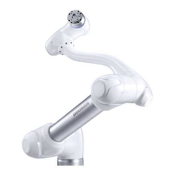
Product Introduction Robot Overview 1.1.1 Names of Each Part Name Name Base Link2 Link1 Tool Flange... -
Page 12: Key Features
“3.4.4 Status and Flange LED Color Flange LED for Each Mode.” I/O port for tool control. Flange I/O (Digital input 3ch, output 3ch) Connector Used for supplying power to and communication of the robot. Doosan Robotics User Manual v2.6.1... - Page 13 Item Description [Option] Controller used for direct teaching. Cockpit Area to install tools. Tool Flange I/O port for tool control. Flange I/O (Digital input 2ch, output 2ch) Displays the robot status with different colors. For more information about robot status, refer to the “3.4.4 LED (1-axis) Status and Flange LED Color for Each...
-
Page 14: Controller Overview
Used to turn ON/OFF the main power of the controller. Power switch Robot cable Used to connect the robot cable to the controller. connection terminal Power connection Used to connect the controller power supply. terminal Doosan Robotics User Manual v2.6.1... - Page 15 Item Description I/O connection terminal Used to connect the controller or peripherals. (internal) To use the Teach Pendant, Smart Pendant, or Emergency Emergency Stop Button Stop buttons, the switch must be set to match the actual Setting switch configuration. Emergency stop button Connects the emergency stop button or smart pendant cable and smart pendant to the controller.
-
Page 16: Teach Pendant Overview
Hand-Guiding Press and hold the button to move the robot freely into a desired button pose. ※ The teach pendant is not a standard item but an optional item, so it must be purchased separately Doosan Robotics User Manual v2.6.1... -
Page 17: Smart Pendant (A-Series)
Smart Pendant (A-Series) Item Description Used to indicate the robot status by displaying the same color as the Robot LED robot status LED to the user. Used to indicate whether the system entered smart pendant mode. Device LED When four input signal buttons (F1 to F4) are pressed, the LED lights Function LED up and indicates the press status There are a total of 11 buttons including four input signal buttons (F1-... -
Page 18: Emergency Stop Button (A-Series)
Emergency Stop Button (A-Series) Item Description Emergency Stop In case of an emergency, press the button to stop robot operation. Button: Doosan Robotics User Manual v2.6.1... -
Page 19: System Configuration
System Configuration Power Command/ Supply/ Monitoring Network Laptop Controller Robot Teach pendant • Laptop: After installing the DART Platform, a work environment identical to the teach pendant can be set up. • Teach Pendant: It is a device that manages the overall system, and it is capable of teaching the robot specific poses and setting robot and controller related settings. - Page 20 Emergency Stop Button: If a laptop is used as part of the system, it acts as the emergency stop button of the teach pendant. • Robot: It is an industrial collaborative robot that can perform transport or assembly tasks with various tools. Doosan Robotics User Manual v2.6.1...
-
Page 21: Safety
Safety Safety Indications of User Manual Failure to observe instructions with this symbol may result in serious accidents Danger that could result in death or serious injury to the operator. Failure to observe instructions with this symbol may result in accidents that Warning cause severe injury to the operator. -
Page 22: Precautions For Use
Do not put fingers inside the controller with power supplied. Live cables are connected, which may lead to electrocution or injury. • Do not modify the robot. Doosan Robots is not responsible for for any issues that occur due to unauthorized modification. •... - Page 23 programming error or robot malfunctioning, as well as damage to the equipment. • Do not expose the robot to strong magnetic fields. This may damage the robot or cause malfunctions. • If the power plug is disconnected or the power is shut off during robot and controller operation, robot and controller failure can occur.
-
Page 24: Types Of Stop Modes For Safety
If the robot end (TCP) is within the Collaborative Zone and if the Nudge function is enabled, the user can apply force to the robot directly (Nudge) to restart work. For more information, refer to “7.5.13 Collaborative Workspace Setting” Doosan Robotics User Manual v2.6.1... -
Page 25: Emergency Stop
Emergency Stop In emergency situations, press the Emergency Stop button on the top right of the teach pendant to immediately stop the system. • Twist the Emergency Stop button clockwise to disengage the emergency stop condition. - Page 26 • If an emergency stop occurred through the port set at Safety I/O, the button capable of accessing the screen for Safety Input setting at the bottom of the emergency stop popup window is enabled. Doosan Robotics User Manual v2.6.1...
-
Page 27: Other Safety Measures
Other Safety Measures The system offers Safety Recovery Mode and Backdrive Mode for user safety and robot recovery. • Safety Recovery Mode: If there is an error with a continuing safety violation or if a robot is to be packed, the user can use Safety Recovery Mode to configure the position and angle of the robot. For more information about Safety Recovery Mode, refer to “10.7 Safety Recovery Mode.”... -
Page 28: System Power Cut-Off
A power switch is installed on the bottom of the controller to cut off system power. Before cleaning or servicing the robot or controller, or before disassembling the system, cut off system power using the power switch. Doosan Robotics User Manual v2.6.1... -
Page 29: Starting Up The Robot
Starting Up the Robot System Power-Up Press and hold the power button on the upper left of the teach pendant. • The power for systems such as the robot, controller and teach pendant is turned on. • Once the system is powered on, the LED indicator for the robot lights up. •... - Page 30 [PC Power ON/OFF only when E-STOP Box is used - Standard Item] Open the controller door, and press and hold the power button located below the bottom right of the Safety board. • To turn off the power, press and hold the button. Doosan Robotics User Manual v2.6.1...
- Page 31 ON/OFF Switch [PC Power ON/OFF when Teach Pendant is used - Optional Item] Press the Power button located on bottom right of the Teach Pendant screen. Press and hold the power button located on the top left of the teach pendant. •...
- Page 32 If the system does not power up, check the power switch at the bottom of the controller. Caution When turning off the system, follow the proper shutdown procedure described in the User Manual. Pulling out the power plug or executing a forced shutdown may cause robot and controller failure. Doosan Robotics User Manual v2.6.1...
-
Page 33: Emergency Stop Button Setting Switch (A-Series)
Emergency Stop Button Setting Switch (A-Series) Configure the EMERGENCY STOP BUTTON SETTING switch on the Case according to components and additional components before connecting and starting up the product. If the setting is not configured according to the guide, the robot will not operate properly. The EMERGENCY STOP BUTTON SETTING switch is located on the bottom left of the board inside the controller door (refer to below). -
Page 34: Booting And Disengaging Packing Position
The DART Platform displays a screen that shows the robot connected to the network after booting, and the process of checking the robot’s serial number and connecting to the robot take place on this screen. Doosan Robotics User Manual v2.6.1... -
Page 35: Disengaging Packaging Pose
3.3.2 Disengaging Packaging Pose The robot is in its packaging pose to allow easy transportation or packaging. To use the robot, it is necessary to disengage the packaging pose. Disengaging Packaging Pose: Tap Status on the initial screen of the teach pendant. Tap the Safety Recovery button. - Page 36 The robot status display on the bottom right of the screen changes from Recovery to Standby. The robot is now in a state where the user can operate it. Press the Close button on the Status screen to close the status window. Doosan Robotics User Manual v2.6.1...
-
Page 37: Robot Mode And State
Robot Mode and State The operation modes of the robot consist of Manual Mode, where the user controls the robot directly, and Auto mode, where the robot operates without direct user control. 3.4.1 Manual Mode This is the mode in which the robot operates according to direct user control. The robot only operates when a button related to an action is pressed, and releasing the button results in stopping the corresponding action. -
Page 38: Automatic Mode
Enable Switch can be connected through the I/O by the setting in the WCM > Robot > Safety I/O. In this case, the Enable Switch must be placed in the center-enable position to allow Play or Start, Resume and Servo On in Automatic Mode. Doosan Robotics User Manual v2.6.1... -
Page 39: Other Mode
3.4.3 Other Mode Unlike normal modes such as manual mode and automatic mode, this is exceptional mode. This mode includes special states such as controller booting, initializing and states related to Backdrive at which you can push robot by hand without drive power. -
Page 40: Status And Flange Led Color For Each Mode
Servo On in the safety recovery mode screen. If it is impossible to release the protective stop input from the Protective Device, cancel the protective stop input setting in the Safety I/O setup menu. Doosan Robotics User Manual v2.6.1... - Page 41 Flange and/or State Mode Description Base LED The Teach Pendant UI is in the actual mode execution screen in a single work space. Pressing the "Execute" button will execute the task Auto Standby White/Green program. White is displayed for a Standalone Zone, green is displayed for a Collaborative Zone..
- Page 42 Backdrive Series) speed threshold during Backdrive Motion. Servo Off LED Off (A- It is identical to Safe Torque Off (STO). Series) The controller is booting and the robot is initialized. Initializing Red Blinking Doosan Robotics User Manual v2.6.1...
-
Page 43: Functional Limits Of Each Robot Series
Functional Limits of each Robot Series The different robot series (A, As, M/H Series) limit the use of functions as follows: • Current-based: Current of motor located on each joint is used. • FTS-based: An FTS (force torque sensor) located on the end of the robot is used. •... - Page 44 (When using O (If the palletizing commands: for the O (FTS-based) for the mode is set to “ON”: Check_force_ singularity singularity 4-Degree of Freedom condition()) section) section) provided for the base (x, y, z, Rz)) Doosan Robotics User Manual v2.6.1...
- Page 45 Control output restriction (Base Rx, Ry orientation): The force or compliance control value for the Base Rx or Ry orientation has not been output. Entering the force or compliance control value of the relevant axis (Base Rx, Ry) will have no effect, and will be ignored as “0.”...
-
Page 46: Robot Safety Setting
The following safety settings must be configured before operating the robot for the first time after installation. Warning Safety-related parameters must be determined through the comprehensive risk assessment, and safety parameter settings and the operation of safety functions must be verified before operating the robot. Doosan Robotics User Manual v2.6.1... -
Page 47: Safety Limit Setting
3.6.1 Safety Limit Setting For more information about the universally applied safety limit, refer to “7.5.2 Robot Limits Setting”. -
Page 48: Space Limit And Zone Setting
For more information about the spatial limit which limits the work space of the robot and the zone settings for configuring safety limits for each zone, refer to “7.5.11 Space Limit and Zone Settings Overview”. Doosan Robotics User Manual v2.6.1... -
Page 49: Application Recovery Mode Screen
Application Recovery Mode Screen If a software error is detected during robot booting, the system enters Application Recovery Mode. This screen offers functions to preserve and restore application data. This screen is only available in English. 3.7.1 Using Application Recovery Mode Functions Item Description This displays the serial number of the connected robot. - Page 50 This restores the application to a specific version. It works the Restore System same as “12.7.2 System Restore” function. If the update fails, the system can be re-installed using the Unified Update “12.7.1 Unified Update” function. Restart This restarts the controller. Doosan Robotics User Manual v2.6.1...
-
Page 51: Series Compatibility Error Screen
Series Compatibility Error Screen The controller stores the execution information of the connected robot. This information varies depending on the robot series, so if a robot of a different series is connected, the series compatibility error screen will be displayed. This screen provides the options of saving the current execution information or resetting the data. -
Page 52: Robot Series Swap
Take caution after swapping to a different model of the same series, as Safety Parameters, TCP, Tool Weight and various user defined settings are maintained. Robot series compatibility may vary depending on the software version. Doosan Robotics User Manual v2.6.1... - Page 53 For a detailed change history of each software version, refer to the Release Note at RobotLAB (https://robotlab.doosanrobotics.com).
-
Page 54: Manual Robot Operation
Manual Robot Operation Jog Operation The robot can be operated manually using the Jog function on the teach pendant. For more information about the jog function, refer to “11 Jog Function.” Doosan Robotics User Manual v2.6.1... -
Page 55: Hand-Guiding Operation
Hand-Guiding Operation The user can change the robot’s pose by directly moving the robot. Use the Hand-guiding button on the teach pendant or use the cockpit located on joint J6 to change the robot’s pose. Caution Before entering the robot’s operation range, press the Hand-guiding button on the teaching pendant one or two times to make sure that the robot does not move when no external force is applied. -
Page 56: Cockpit Button (Five Buttons)
Axis Lock: Changes the pose according to the Z- axis of the tool coordinates User Setting Button Surface Lock: Changes the pose according to the X-Y surface of the tool coordinates Doosan Robotics User Manual v2.6.1... - Page 57 Item Description Point Lock: Changes the angle only from the reference point of the tool coordinates Angle Lock: Changes the position only with the current TCP angle locked For more information about the settings, refer to “12.3.2 Cockpit Setting.”...
-
Page 58: Cockpit Button (Six Buttons)
Axis Lock: Changes the pose according to the Z-axis of the tool coordinates User Setting Button Surface Lock: Changes the pose according to the X-Y surface of the tool coordinates Point Lock: Changes the angle only from the reference Doosan Robotics User Manual v2.6.1... - Page 59 Item Description point of the tool coordinates Angle Lock: Changes the position only with the current TCP angle locked For more information about the settings, refer to “12.3.2 Cockpit Setting.” Saves the current robot pose. For more information, refer to “8.7.3 Save Pose Button Skill Command Work Point Setting with Cockpit Buttons.”...
- Page 60 Moving the robot while holding the body may not trigger a reaction from the robot. For details on the functional limits of each robot series, please refer to ”3.5 Functional Limits of each Robot Series”. Doosan Robotics User Manual v2.6.1...
-
Page 61: Clamping Escape By Cockpit
4.2.4 Clamping Escape by Cockpit Clamping Escape function can only be used when it is enabled at “12.3.2 Cockpit Setting”. Clamping Escape function can be enabled with buttons for 5 cockpit buttons, and with buttons for 6 cockpit buttons. Clamping Escape function can be used with 2 paths on the Teach Pendant screen. Entering from Servo Off status >... -
Page 62: Robot Teaching And Execution
Programming Manual. Task Writer uses DRL (Doosan Robot Language) to create and execute programs suited for the user’s process, and it also features a Custom Code function where the user can load and execute task programs created by referring to the Programming Manual. -
Page 63: System Operation Program Outline
System Operation Program Outline The UI of the system operation program consists of the following: Item Description This area displays the name of the task currently being executed and Status Display the current work status. Area This area is where the user enters and changes settings when performing work using the robot. -
Page 64: Status Display Area
Pressing the Workcell Manager, , Task Builder or or Task Writer button on the main menu without closing the popup window using the button on the Status, Jog or Settings screen will enter a new screen rather than returning to the previous screen. Doosan Robotics User Manual v2.6.1... -
Page 65: Main Menu
Main Menu Major functions of the system can be checked in the main menu. Tap each menu button to go to the corresponding menu screen. • Home: It is the initial screen of the system, and information and a work progress graph of the current task are displayed. -
Page 66: Home Screen Overview
Home Screen Overview Information about the current task status and task, and work progress graphs are displayed. Item Description The total number of lines of the task program is displayed. Tapping the number indicating the program line will go to Task Builder or Task Writer. - Page 67 Item Description Displays the number of peripherals connected to the task. Tap this item to go Peripherals to the peripheral setting screen of Workcell Manager. For more information about peripherals, refer to “7.8 Peripheral Setting”. Displays the target number, work count, and time of the current task. The Work Status information displayed can be selected using checkboxes.
-
Page 68: Task Execution And Stopping
Check Log Message Displays log information of the task. Task Execution Displays task repetition count, play time and average one cycle Information and execution time. Tap the Stop button to stop the current task. Stop Doosan Robotics User Manual v2.6.1... -
Page 69: Load Saved Tasks
Load Saved Tasks Tasks saved on the system can be loaded from the Home screen. Tap the menu button on the top left of the Home screen. Tap Open. A list of tasks saved on the system is displayed on the screen right. Tap the task to execute from the list. -
Page 70: Tool Setting
Workcell Manager screen, so the tool center point, weight and shape of the end effector to be used must be set in Tool Settings of the tool. Item Description Tool Setting It runs the Tool Setting popup. Button Doosan Robotics User Manual v2.6.1... - Page 71 Select the Tool Setting button. Select the desired Workcell item from the Tool Center Point, Weight or Tool Shape. Press the Setting button to save the tool center point, weight or shape of the corresponding Workcell item. Note The robot’s tool center point and tool weight can be set to default where no input is made by pressing the Reset button.
-
Page 72: Workcell Manager
General World Coordinates Robot Limits Safety I/O Robot Normal I/O Safety Stop Mode Robot installation pose Tool weight Tool shape User Coordinates Nudge Doosan Robotics User Manual v2.6.1... - Page 73 Item Description Space Limit Collaborative Zone Crushing Prevention Zone Collision Sensitivity Reduction Zone Tool Orientation Limit Zone Custom Zone End effectors can be added to the robot, and the added end effector is displayed. ...
-
Page 74: Add Workcell Item
Select Note The Workcell Item name must consist of 20 alphabet characters and numbers. The only special character allowed is the underscore, and the name cannot have blank space at the front or back. Doosan Robotics User Manual v2.6.1... -
Page 75: Deprecated Workcell Item
Deprecated Workcell Item Workcell items are managed in two states: Normal, where new items can be registered, and Deprecated, where maintenance is no longer possible. Workcell Items can be updated due to increased usability and additional motion improvements. If a Workcell Item is updated, the existing Workcell Item becomes deprecated, and it cannot be added or edited. - Page 76 Tapping the Edit button cannot edit the setting, but deletion is possible. Doosan Robotics User Manual v2.6.1...
-
Page 77: Unavailable Workcell Items
This displays the Workcell Item Package Version compatible with the current SW, Workcell Items that are not installed, and the name and type of Workcell Items that are not compatible. In order to properly use such Workcell Items, the corresponding Workcell Item must be downloaded from Doosan Mate and installed. -
Page 78: Robot Setting
Rotate or move the simulation screen. Tap the button and drag or tap the screen to control. Simulator Sets the direction of the simulator. The simulation is displayed Direction Setting from the selected direction. Workspace Displays the workspace of the Workcell. Doosan Robotics User Manual v2.6.1... - Page 79 Item Description Delete Deletes the current Workcell. Draft: This temporarily saves the workspace settings of Workcell. Confirm: This saves the current or confirmed temporary save of Draft the workspace settings of Workcell. Confirm (For safety-related Workcells only, the Confirm button is displayed after Confirm Temporary Save has been performed.
-
Page 80: World Coordinates Setting
Task Builder and Task Writer. To set World Coordinates, tap the Add button on the Robot Workcell and select Robot > World Coordinates. Tap the Edit button at the top. Doosan Robotics User Manual v2.6.1... - Page 81 Please refer to the figure depicting the relationship between the World Coordinate and Base Coordinate, as well as related precautions. Warning When changing the relationship between World and Base coordinates, the teaching point of World Coordinates or user coordinates based on World Coordinates can change. Changes are only recommended when the actual relationship between World Coordinates and Base Coordinates are changed.
- Page 82 For more information, refer to “7.5.1 World Coordinates Setting”. When a tool is installed or replaced, the weight of the tool must be configured before operating the robot. For more information about setting tool weight, refer to “7.5.8 Tool Weight Setting”. Doosan Robotics User Manual v2.6.1...
-
Page 83: 7.5.2 Robot Limits Setting
7.5.2 Robot Limits Setting It sets the safety limits of safety monitoring functions. Note The limit and initial safety settings may vary according to the robot lineup. Safety limits is the condition where the safety-rated monitoring function triggers the stop function. - Page 84 Speed. The Joint Speed Limits setting screen layout is composed as follows: Item Description Joint Speed It can limit the speed of each joint. Default Value It resets the Joint Speed Limits settings to default values. Doosan Robotics User Manual v2.6.1...
- Page 85 Joint Angle Limits To set the joint angle limits, go to the Robot Workcell and select Robot > Robot Limits > Joint Angle. The Joint Angle Limits setting screen layout is composed as follows: Item Description Angle Range of It can limit the angle range of each joint.
-
Page 86: 7.5.3 Safety I/O Setting
Low: Follow Protective Stop – SS2. Protective Stop(L) - Auto Rising (Low to High): the task resumes automatically Reset & Resume (R) without manual reset or resume. Warning Resuming automatic operation without manual intervention can be dangerous, Doosan Robotics User Manual v2.6.1... - Page 87 Signal Name Description DO conduct a comprehensive risk assessment to confirm that using this signal is safe It is used to reset the Interrupted state by Protective Stop Interlock Reset (R) Rising(Low to High): Reset the restart interlock and permit return to normal standby state ...
- Page 88 Low: Robot is in Interrupted, Recovery, or Auto Measure state High: Robot is operating at the reduced speed due to external Reduced Speed Activation safety input Normal Speed (L) Low: Robot is operating as normal speed Doosan Robotics User Manual v2.6.1...
- Page 89 Description Signal Name High: Robot is operating as normal speed Low: Robot is operating at the reduced speed due to Reduced Speed (L) external Reduced Speed Activation safety input High: The robot is not in Auto Mode Auto Mode (L) ...
-
Page 90: 7.5.4 Normal I/O Setting
Designated Zone normal output Low: If the TCP is inside a Zone linked with the Designated Zone noraml output High: Task is not in operation Task Operating (L) Low: Task is in operation Doosan Robotics User Manual v2.6.1... - Page 91 Description Signal Name This is used to notify the operator that the robot joint is actually operating. Robot In Motion (L) High: The robot is stopped Low: The robot is operating This is used to notify the operator that mastering is required due to an issue in the home position setting.
-
Page 92: 7.5.5 Safety Stop Modes Setting
Momentum Limit Violation: It sets the Stop Mode when the robot momentum exceeds the momentum limit. • Mechanical Power Limit Violation: It sets the Stop Mode when the mechanical power of the robot exceeds the power limit. Doosan Robotics User Manual v2.6.1... -
Page 93: Robot Installation Pose Setting
7.5.6 Robot Installation Pose Setting The robot can be installed at any angle. To configure the robot installation pose, tap the “Add” button on the Robot Workcell and select Robot > Robot Installation Pose. The robot installation pose can be entered manually or calculated automatically. Item Description Auto Calculate... - Page 94 The H Series models do not support robot installation pose functions. Installation must be done on the ground. Auto Calculate is not supported in models without Force Toque Sensors. Doosan Robotics User Manual v2.6.1...
-
Page 95: Tool Shape Setting
7.5.7 Tool Shape Setting To set the robot tool shape, tap the Add button on the Robot Workcell and select Robot > Tool Shape. The Safety Password is required during setup. Tool shape can be set by adding Cuboid, Sphere, and Capsule shapes. Select a shape that matches the tool and tap the Confirm button. -
Page 96: Tool Weight Setting
(the center of gravity can be a negative real number or 0) Remove all obstacles before executing auto calculate. To execute Auto Calculate of 4, 5 and 6, the 3-axis angle must be greater than +30 degrees or less than -30 degrees. Doosan Robotics User Manual v2.6.1... - Page 97 Note that safety monitoring functions are disabled during Auto Calculate. During Auto Calculate, the Auto Calculate button becomes the Stop button, which allows the user to stop Auto Calculate. If calculation is stopped, the weight and center of gravity values are reset.
-
Page 98: User Coordinates Setting
Make sure to read the description image and cautionary items of the User Coordinates. User Coordinates can be created based on 1-point, 2-points and 3-points. It is possible to load pallet coordinates from Advanced Options and apply them to User Coordinates points. Doosan Robotics User Manual v2.6.1... -
Page 99: Nudge Setting
7.5.10 Nudge Setting If the robot is stopped by Safety Stop Mode SS2 or RS1 within a Collaborative Zone, the Interrupted state can be reset and task can be resumed with Nudge input. Nudge option can be enabled on user defined sections. -
Page 100: Space Limit And Zone Settings Overview
Custom Zone: Various safety limits can be overridden, depending on the application. By selecting the Valid Space, it is possible to select whether the Inspection Point cannot enter the designated space or cannot leave the space. Doosan Robotics User Manual v2.6.1... - Page 101 With the Zone Margin, the expanded volume from the designated volume with specified points can be easily configured. Safety Limits that is overridden in Zone has the priority below. • Safety limit overridden inside Zone has priority over the global Safety Limits •...
- Page 102 To configure the radius, enter the positions of the center point and endpoint of the sphere, and to configure the diameter, enter two endpoints of the sphere, then tap the Save Pose button. Sphere Doosan Robotics User Manual v2.6.1...
-
Page 103: Space Limit Settings
7.5.12 Space Limit Settings To set space limits for the robot, tap the Add button on the Robot Workcell and select Space Limit>Cube, Cylinder, Multi-plane Box, Sphere or Tilted Cuboid. The safety password is required during setup and activation. Enter the Workcell Name in the Workcell Name field on the top of the Workcell Setting screen. Set the pose information according to the Space Limit shape along with the Inspection Point, Valid Space and Zone Margin in the Geometry tab. -
Page 104: Collaborative Zone Settings
Draft. Verify that all parameters displayed are the same as what are Intended to be set, then check Confirm draft and press Confirm Press the Activate Toggle button to apply the Collaborative Zone. Doosan Robotics User Manual v2.6.1... -
Page 105: Crushing Prevention Zone Settings
7.5.14 Crushing Prevention Zone Settings To set the Crushing Prevention Zone, tap the Add button on the Robot Workcell and select Crushing Prevention Zone > Cuboid, Cylinder, Multi-plane Box, Sphere or Tilted Cuboid. The safety password is required during setup and enablement. Enter the Workcell Name in the Workcell Name field on the top of the Workcell Setting screen. -
Page 106: Collision Sensitivity Reduction Zone Settings
Verify that all parameters displayed are the same as what are Intended to be set, then check Confirm draft and press Confirm Press the Activate Toggle button to apply the Collision Sensitivity Reduction Zone. Doosan Robotics User Manual v2.6.1... -
Page 107: Tool Orientation Limit Zone Settings
7.5.16 Tool Orientation Limit Zone Settings To set the Tool Orientation Limit Zone, tap the Add button on the Robot Workcell and select Tool Orientation Limit Zone> Cuboid, Cylinder, Multi-plane Box, Sphere or Tilted Cuboid. The safety password is required during setup and enablement. Enter the Workcell Name in the Workcell Name field on the top of the Workcell Setting screen. -
Page 108: Custom Zone Settings
If the Override Option is not checked, the most restricted limit between the limits of High Priority Zone and Global Reduced Limit is selected. ⚫ If the Override Option is checked, the limit of High Priority Zone is selected. Doosan Robotics User Manual v2.6.1... - Page 109 ◆ If there are two or more Zones set as High Priority Zone, the safety limit for that position depends on Override Option. ⚫ If there is any High Priority Zone that Override Option is NOT checked, the most restricted limit among the Global Reduced Limit and the limits of High Priority Zones without Override Option is selected ⚫...
-
Page 110: End Effector Setting
(tools and screwdrivers). In addition, user-built tools and screens can be added as Workcell Items. Doosan Robotics provide a web-based App Builder development eco system for Workcell Item app development. Manuals and web services for App Builder can be found at the Developer LAB. - Page 111 Item Description Signal Type: Sets the output signal type (controller, flange). Port Number: Select the end effector output signal port. Signal: Tests the output signal status. Checks and sets the input signal. (If a function is enabled in Workcell Item Action, its name and signal type are disabled.) ...
-
Page 112: End Effector I/O Signal Setting
Enter the Workcell name in the Workcell Name field at the top of the Workcell Setting screen. Select the port number for I/O signal setting. Default Value displays the initial value set by the App Builder. Tap the button. Confirm Doosan Robotics User Manual v2.6.1... -
Page 113: End Effector I/O Testing
7.6.3 End Effector I/O Testing To test the operation status of the connected end effector, follow the procedure below. Select the end effector to test and tap the Edit button. Tap the On/Off button of the Signal to test the output signal. Select a function among the Workcell Item Actions and tap the Test button to test the end effector function. -
Page 114: Tool Center Point (Tcp) Setting
Coordinate axis of “TCP Coordinate” (X,Y,Z): The coordinate axis is defined at the end of the tool installed on the end of the flange or working point. The rotation angle of the “TCP Coordinate” is defined based on the “Flange Coordinate” in the order of 1) to 3) of the following: Doosan Robotics User Manual v2.6.1... - Page 115 Z’ 1) Rotated by A 2) Rotated by B Z” along Axis - Z along Axis - Y X’ Y” Y’ X” Flange Coord. 3) Rotated by C along Axis - Z” TCP Coord. 1) Rotate A degrees along the z axis of the Flange Coordinate 2) Rotate B degrees along the y’...
-
Page 116: Tool Center Point Setting Based On Other End Effectors
Configure the tool Z-axis rotate angle of the configuring end effector and reference end effector. Click the Auto Calculate button on the bottom, check whether the calculated TCP is automatically entered and tap the Confirm button. Doosan Robotics User Manual v2.6.1... - Page 117 Note The configuring end effector and base end effector must be symmetrical on the tool Z axis.
-
Page 118: Machine Tool Setting
Machine tool settings are similar to those of the gripper settings. For more information about each machine tool settings, refer to the separate Reference Manual provided. Doosan Robotics User Manual v2.6.1... -
Page 119: Peripheral Setting
Peripheral Setting Peripherals are Workcell items that are not categorized as a robot, end effector or machine tool, but interact with the robot. Peripherals that can be registered in the Workcell Manager are as follows: Category Type Description Feeder Shooting Bolt Feeder This is a device that supplies bolts to the end of a screwdriver using a tube and air pressure. -
Page 120: Others
7.8.1 Others The others category settings are similar to those of the gripper settings. For more information about other category settings, refer to the separate Reference Manual provided. Doosan Robotics User Manual v2.6.1... -
Page 121: Vision
7.8.2 Vision For more information about Vision settings, refer to the separate Reference Manual provided. -
Page 122: Task Builder
Task Builder After registering and configuring all Workcell items in the Workcell Manager, a program to execute the robot task must be created using commands or skills. With Task Builder, the user can create a new task, enter skills or commands, or create tasks using templates recommended by the system. -
Page 123: Template
8.1.2 Template A template is a bundle of skills that compose a work procedure used with a combination of Workcell items when a particular Workcell item is registered. It is possible to easily create a task with the settings of skills already in the template without worrying about the work process. To create a new task using a template, follow these steps: Tap the Template on the initial screen of Task Builder. -
Page 124: Save Task
To save an edited task, tap the Menu button and tap Save. Note If the file is not saved for the first time, a confirmation window appears. Tap the Confirm button to save it to an existing file. Doosan Robotics User Manual v2.6.1... -
Page 125: Save Task As
8.1.4 Save Task As To save the task as a different file, follow these steps: Tap the "Menu" button and tap the “Save as” button. When the Save as window appears, enter the task name and tap the Confirm button. When the save is complete, the Save Complete window appears. -
Page 126: Editing Workcell Items
Tap the Menu button and press the selected Workcell item. From the current task, it is possible to add or remove new Workcell items in the current task or Workcell list. Doosan Robotics User Manual v2.6.1... -
Page 127: Save Task On External Storage Device
8.1.6 Save Task on External Storage Device To save an opened task to an external storage device, follow these steps: Connect an external storage device to the USB slot. Only external storage devices with FAT32 file systems can be used. Tap the Menu button and tap Export. -
Page 128: Load Saved Tasks
Select a task to open from the file list and tap the Open button. Searches for tasks in the file list can be made using the filter function. Search in latest, oldest, alphabetical order, and reverse order is possible. Doosan Robotics User Manual v2.6.1... -
Page 129: Delete Saved Tasks
8.1.8 Delete Saved Tasks To delete a saved task, follow these steps: Tap Saved Files on the initial screen of the Task Builder. If a task is being edited, tap the Menu button and tap Open. Select a task to delete from the file list and tap the "Delete" button. -
Page 130: Import Tasks On External Storage Devices
Tap the Import button on the bottom right. When the task file is saved on an external storage device, the Save Complete window appears. To load a task file saved on the system, refer to “8.1.7 Load Saved Tasks.” Doosan Robotics User Manual v2.6.1... -
Page 131: Task Builder Commands
Task Builder Commands The user can create task programs using motion commands, flow control and other commands and skill commands from Task Builder. For more information about commands, refer to the manual provided separately. • Motion Command: These are commands used to adjust or change the robot’s pose. Used to move the robot to the target joint coordinates. - Page 132 This is used to save the user-designated information in a log during Comment task execution. Messages are limited to within 256 bytes. It is recommended that the text be concise. For long text, some content is omitted with an ellipsis (…). Doosan Robotics User Manual v2.6.1...
- Page 133 Formatting code such as newline (\n) or carriage return (\r) is not allowed. This is used to insert and execute a DRL code during task execution. Custom Code This is used to define a variable during task execution. Define This is used to display a popup screen during task execution.
-
Page 134: Deprecated Skill Command
In the property window of a deprecated skill command, the phrase “Deprecated Item” is displayed. If a deprecated skill command is present, it is recommended to replace it with an updated skill command. Doosan Robotics User Manual v2.6.1... -
Page 135: Edit Task
Edit Task When a task is created, the user can add commands in the Task List, and when the Properties of the added command are configured, the task program can be executed. The Task Builder screen offers an edit function for adding/deleting/copying commands or changing the order of commands. The Task Builder commands consist of motion commands, flow control and other commands, and skill commands. - Page 136 System variables can be registered without any limit on the number starting from software version V2.8. If there are too many system variables registered, there may be long loading times for task execution. Doosan Robotics User Manual v2.6.1...
-
Page 137: Add Command
8.4.2 Add Command To add a command, follow these steps: Select the location to add a command in the Task List. A command is added to the next line of the selected location. Select the command to add from the Command tab. -
Page 138: Delete Command
8.4.3 Delete Command To delete a command, follow these steps: Select a command to delete and tap the Delete button in the command edit tools. When a confirmation window appears, tap the Confirm button. Doosan Robotics User Manual v2.6.1... -
Page 139: Paste Command
8.4.4 Paste command To copy/cut and paste a command to the task list, follow these steps: Select command to copy or cut. Tap the Copy or Cut button on the command edit tool. Select the location to paste the command. ... -
Page 140: Setting And Applying Command Properties
If necessary, comments for the command can be entered. • The properties of a command are applied only after the Confirm button is tapped. For more information about command properties, refer to the Reference Manual provided separately. Doosan Robotics User Manual v2.6.1... -
Page 141: Motion Command Property Setting
Motion Command Property Setting 8.6.1 Waypoint Setting To configure the waypoint of a command, follow these steps: Select the type (Absolute, Relative) of reference coordinate and coordinate value. Either use the jog function or perform direct teaching to move the robot to the desired position. Tap the Save Pose button to save the robot tool position. -
Page 142: Speed Setting
If a heavy (15 kg or more) tool is attached, it is recommended to set the acceleration value to the same amount or less. (Speed:Acceleration Ratio = 1:1) If a high acceleration is set, the robot may vibrate during acceleration/deceleration. Doosan Robotics User Manual v2.6.1... -
Page 143: Program Link Mode Setting
8.6.3 Program Link Mode Setting Execute the following lines simultaneously with the motion to control the flow of the program. • Synchronized: Program flow is put on hold until the motion ends. • Asynchronized: This executes the following line simultaneously with the motion. This can be utilized for tasks such as verifying external signals or delivering output during motion. -
Page 144: Blending Mode Setting
However, the blending motion is available if all options (toggle buttons) except for approach pose/retract pose are disabled when a skill is added. Doosan Robotics User Manual v2.6.1... -
Page 145: Multi-Segment (Waypoint) Setting
8.6.5 Multi-Segment (Waypoint) Setting Depending on the motion command, it may be necessary to configure two or more waypoints. Each waypoint is referred to as a segment, and adding a waypoint will add a line at the bottom of the command. -
Page 146: Skill Command Property Setting
Move to Approach Pose: This is a point available to move to the Approach Pose. It is set in the Z direction from the Approach Pose, and a different direction can also be selected. The Approach Distance entered is automatically calculated for the Action Pose and moves to the corresponding point. Doosan Robotics User Manual v2.6.1... - Page 147 Move to Reference Pose: This is the point on the workpiece where the End Effector performs work. To set detailed coordinates other than the velocity and acceleration for the reference pose, press the button on the right side of the reference pose. However, using the relative coordinates tab while setting the detailed motion can cause a malfunction during skill execution, so make sure to use the absolute coordinates for reference point teaching.
- Page 148 Move to End Pose: If the End Effector execution target does not end with a single motion, there may be an intermediate point and an end point, and the Action End Pose is the point where the work ends. (i.e. Door_OpenClose Skill – End Pose) Doosan Robotics User Manual v2.6.1...
-
Page 149: Compliance Control And Contact Check
With the Compliance Control and Contact Sensing functions, which is the unique force control technology of Doosan Robotics, it is possible to easily perform teaching without repeated operation for accurate point designation since it allows position deviation within a tolerance range between the workpiece and surrounding items during robot operation. - Page 150 If FTS is not installed when using the A-Series, the Contact Detection function cannot be used. In this case, the use of compliance control is limited, and stiffness can be modified only in the translation (X, Y, Z) direction. Doosan Robotics User Manual v2.6.1...
-
Page 151: Skill Command Work Point Setting With Cockpit Buttons
8.7.3 Skill Command Work Point Setting with Cockpit Buttons Cockpit buttons can be used to configure the action pose. For example, with the Pick skill command: Add a skill command from Task Builder and tap the added skill command. Perform direct teaching to the skill’s action pose to move the robot. Press the Save Pose button on the cockpit. -
Page 152: Execute Task Program
Virtual mode: Uses a simulator screen to test the task in the task list. Total time Displays the total time elapsed after the task execution. Simulator Zooms into the simulated robot model. Zoom-in button Doosan Robotics User Manual v2.6.1... - Page 153 Item Description Simulator Zooms out from the simulated robot model. Zoom-out button Rotate button : Rotates the simulation screen with the robot base as Rotate and pan a central axis. button Pan button : Moves the simulation screen horizontally and vertically. Viewpoint button Sets viewpoints with the robot model as the control point.
-
Page 154: Real Mode Screen: End Effector Information Tab
I/O Information Tab: Displays the I/O information of the controller and the flange. Displays the tool center point information configured through the tool Tool center point center point and weight configuration functions of the set TCP information area command or the jog. Doosan Robotics User Manual v2.6.1... - Page 155 It is recommended to test the robot program by designating temporary waypoints outside another machine’s work space. Doosan Robotics is not responsible for damages that occur due to programming error or robot malfunctioning, as well as damage to the equipment.
-
Page 156: Real Mode Screen: I/O Information Tab
Displays the controller digital I/O signals of the current task. Controller digital If the digital signal is a high signal, the icon is displayed in I/O signal sky blue. If the digital signal is a low signal, the icon is displayed in Doosan Robotics User Manual v2.6.1... - Page 157 Item Description gray. Displays the flange digital I/O signals of the current task. Flange digital I/O If the digital signal is a high signal, the icon is displayed in sky blue. signal If the digital signal is a low signal, the icon is displayed in gray.
-
Page 158: Execute Task
Tool center position and tool weight information on the play information screen are only displayed properly when the Set TCP command is executed or the tool center position and weight of the jog are set. Commands that had issues occur during program execution are highlighted with orange. Doosan Robotics User Manual v2.6.1... -
Page 159: Task Writer
Task Writer is intended for advanced users familiar with program coding. It allows complex motions that cannot be executed with basic commands to be created using DRL (Doosan Robot Language) and Custom Code, which allows the user to load and execute programs created or saved on an external storage device. -
Page 160: Save Task
To save an edited task, tap the Menu button and tap Save. Note If the file is not saved for the first time, a confirmation window appears. Tap the Confirm button to save it to an existing file. Doosan Robotics User Manual v2.6.1... -
Page 161: Save Task As
9.1.3 Save Task As To save a task as different file, follow these steps: Tap the "Menu" button and tap the “Save as” button. When the Save as window appears, enter the task name and tap the Confirm button. When the save is complete, the Save Complete window appears. -
Page 162: Save Task On External Storage Device
When the Save as window appears, enter the task name and tap the Confirm button. When the save is complete, the Save Complete window appears. Note The file extension of the saved task file is “tw”. Doosan Robotics User Manual v2.6.1... -
Page 163: Load Saved Tasks
9.1.5 Load Saved Tasks To load a saved task, follow these steps: Tap Saved Files on the main screen of Task Writer. If a task is being edited, tap the Menu button and tap Open. Select a task to open from the file list and tap the Open button. Searches for tasks in the file list can be made using the filter function. -
Page 164: Delete Saved Tasks
Tap Saved Files on the main screen of Task Writer. If a task is being edited, tap the Menu button and tap Open. Select a task to delete from the file list and tap the "Delete" button. Doosan Robotics User Manual v2.6.1... -
Page 165: Import Tasks On External Storage Devices
9.1.7 Import Tasks on External Storage Devices To import a task saved on an external storage device, follow these steps: Connect the external storage device with the task file to the USB slot. Tap the Import on the Task Writer initial screen. Tap the Search button. -
Page 166: Export Task To External Storage Device
The export popup window appears. Select the external drive to export the task and tap the "Confirm" button. The Save As popup window appears. Enter the task name in the popup window and tap the "Confirm" button. Doosan Robotics User Manual v2.6.1... -
Page 167: Edit Task Program
Edit Task Program The edit screen of Task Writer is identical to that of the edit screen of Task Builder, and the editing features are also identical. For more information about the edit task program, refer to “8.4 Edit Task”. Note ... -
Page 168: Task Writer Command
This is used to return to the first command of a repetition statement Continue (Repeat). This is used to exit the repeat execution command (Repeat). Break This is used to end task execution. Exit This is used to define a subroutine within the task. Doosan Robotics User Manual v2.6.1... - Page 169 This is used to execute the defined subroutine. Call Sub This is used to define a thread within the task. Thread This is used to execute the defined thread. Run Thread This is used to end thread execution. Kill Thread This is a command to define a thread within the task.
- Page 170 In models without Force Toque Sensors, Rx, Ry and Rz values of Weight Measure, Nudge, Compliance commands, and A, B and C values of Force command are not supported. The Watch Smart Pendant command provides functions to control conditions using the Function button of the Smart Pendant Doosan Robotics User Manual v2.6.1...
-
Page 171: Setting And Applying Command Properties
Setting and Applying Command Properties Configuring and applying the commands in Task Writer are identical to those of Task Builder. -
Page 172: Execute Task Program
Execute Task Program The execution of task programs in Task Writer is identical to that of Task Builder. Doosan Robotics User Manual v2.6.1... -
Page 173: Debug Screen
Debug Screen The debug mode of the Task Writer screen is structured as follows: Item Description Sets the robot test play debug mode. Debug Sets a break point in a command. When the command is reached Break Point after executing the task, the robot does not execute the task and Button stops. -
Page 174: 10. Monitoring And Testing
Supplies the driving power that moves each joint of the robot. Manages the digital and analog I/O status of the controller and flange. Checks and tests the digital and analog I/O devices of the controller I/O Test and flange used by the task. Doosan Robotics User Manual v2.6.1... - Page 175 Item Description Modbus Test Tests the signals of the set Modbus device. Job Space Displays encryption of the entire job space data registered to check whether the job space setup has been modified. Status Value Safety Setup Displays encryption of the entire safety data registered to check whether the safety setup has been modified.
-
Page 176: I/O Status Check
If the digital signal is High even when the digital input is set as the safety input, the icon is displayed in blue, and if it is Low, it is displayed in gray. Only two flange I/Os of the flange digital input of A-Series are displayed. Doosan Robotics User Manual v2.6.1... -
Page 177: Controller Analog Input Check
10.2.2 Controller Analog Input Check Press the drop-down list of the analog input of the controller to select the item to check. Check the analog input information of the selected item displayed on the screen. Note The analog input value cannot set the input value in the status window. -
Page 178: Controller/Flange Digital Output Setting
The icon changes to light green and the corresponding port is enabled when the On icon is pressed. The icon changes to light green and the corresponding port is disabled when the Off icon is pressed. Only two flange I/Os of the flange digital output of A-Series are displayed. Doosan Robotics User Manual v2.6.1... -
Page 179: Controller Analog Output Setting
10.2.4 Controller Analog Output Setting Press the drop-down list of the analog output of the controller to select the item to set. Analog output information of the selected item is displayed on the right side of the drop- down list. ... -
Page 180: I/O Test
Port Name The port name of the I/O device for testing can be designated. I/O Test A signal can be sent to the corresponding port. Initialization Initializes all signals of the device as off. Doosan Robotics User Manual v2.6.1... -
Page 181: Modbus Test
10.4 Modbus Test This is the menu to check and test Modbus signals set at Modbus TCP, Modbus RTU, and predefined Modbus. Item Description Select the Modbus type to check. TCP, RTU, and predefined Modbus Modbus Type are available. Displays the list of IPs/Ports of the slave set of the selected Modbus Slave type. -
Page 182: Servo On
To shift from Servo On to Servo Off, tap the Status button of the main menu and tap the Servo Off button in the top right corner of the screen. Note In the Settings screen, if the safety signal I/O, POS_3_ENABLE_SWITCH, is set, Servo On is available only if this signal is inputted. Doosan Robotics User Manual v2.6.1... -
Page 183: Backdrive Mode
10.6 Backdrive Mode Backdrive allows the robot joint control with only the brake and without power driving the motor. This function is used when the robot cannot return to normal with Safety Recovery mode or Hand-guiding. With Backdrive mode, the user can engage or disengage the brake of each joint. The process of setting Backdrive mode is as follows: Tap the Status button on the main menu and tap the Backdrive button. -
Page 184: Safety Recovery Mode
Jog or program. In such cases, Software Recovery mode is used to reset the robot to normal. • Packaging Mode: For packaging and transporting the robot, the robot can be set to predefined values (which go beyond the normal operation angle limit) for packaging. Doosan Robotics User Manual v2.6.1... -
Page 185: Using Software Recovery Mode
10.7.1 Using Software Recovery Mode To use the software recovery mode, follow these steps: Tap the Safety Recovery button in the Status window. Tap each joint button on the right side of the Software Recovery screen, and use button to set the position. Or press the buttons of the Cockpit to adjust the joint angle by direct teaching. -
Page 186: Packaging Mode Setting
The robot automatically moves to the set packaging pose. To release the packaging pose, tap the Release Packaging Pose button to move the robot to home position, then tap the Packaging Mode toggle button to disable packaging mode. Doosan Robotics User Manual v2.6.1... -
Page 187: 11. Jog Function
11. Jog Function In Jog mode, the user can navigate the entire work space or set the operation space the user configured as the robot operation space. The movement angle of each axis can be limited according to the selected operation space and joint angle limit of the safety setting. To use the jog function, tap the Jog button on the main menu. -
Page 188: Jog Screen
This speed influences the speed controlled by the jog and movement buttons. It configures whether to operate the robot in real mode while in jog mode. Real Mode On ( ): The robot actually moves. Off ( ): The simulator operates. Doosan Robotics User Manual v2.6.1... - Page 189 Item Description It selects the alignment direction of the robot displayed in the Simulator simulator. Pressing each direction button aligns the robot in the Alignment corresponding direction. It displays robot workspace information registered in the Workcell Robot Workspace Manager in the Jog Simulator. Press the drop-down menu to select the workspace to display.
-
Page 190: Execute Based On Joint
Select the Joint tab on the Joint screen. Select the axis (J1-J6) to adjust the angle. Press and hold the Direction Button ( ) to adjust the angle of the corresponding axis. Note Safety area does not apply in virtual mode. Doosan Robotics User Manual v2.6.1... -
Page 191: Execute Based On Robot Base
11.1.2 Execute based on Robot Base To move the robot based on the robot base, follow these steps: Select the Task tab on the Jog screen. Select the display coordinates to be used as the base and select the Base as the reference point of the task coordinates. -
Page 192: Execute Based On World Coordinates
Select the display coordinates to be used as World Coordinates and select World as the reference point of the task coordinates. Select World Coordinates to move. Press and hold the Direction Button ( ) to move the corresponding axis. Doosan Robotics User Manual v2.6.1... -
Page 193: Execute Based On Robot Tool
11.1.4 Execute based on Robot Tool To move the robot based on the robot tool, follow these steps: Select the Task tab on the Jog screen. Select Base or World as the display coordinates and set the Tool based on the reference point of the task coordinates. -
Page 194: Movement Screen
If the slider pointer is at 100%, the corresponding maximum joint Speed speed on the Move tab is 30 deg/s, and the maximum task speed is 250 mm/s. The speed influences the jog and button operation speed. Doosan Robotics User Manual v2.6.1... -
Page 195: Moving With Angle Setting
11.2.1 Moving with Angle Setting To move the robot at a specific angle, follow these steps: Select the Move tab and select the Joint tab. Enter the target angle of the robot joint. Enable the Real Mode. Tap and hold the Move to Corresponding Pose button to adjust the robot joint angle. -
Page 196: Move With Base Reference Coordinates
Select Base as the display coordinates and select the Base tab. Configure the pose to move with reference to the base. Tap and hold the Move to Corresponding Pose button to go to the set coordinate. Doosan Robotics User Manual v2.6.1... -
Page 197: Move With World Coordinates Reference Coordinates
11.2.3 Move with World Coordinates Reference Coordinates To move the robot based on World Coordinates, follow these steps: Select the Move tab and select the Task tab. Select World as the display coordinates and select the World tab. Configure the pose to move with reference to the World Coordinates. Tap and hold the “Move to Corresponding Pose”... -
Page 198: Move With Tool Reference Coordinates
Select the Move tab and select the Task tab. Select the Tool tab. Configure the pose to move with reference to the tool. Tap and hold the Move to Corresponding Pose button to go to the set coordinate. Doosan Robotics User Manual v2.6.1... -
Page 199: Align Screen
11.3 Align Screen The robot’s alignment reference can be set on the Align screen. Item Description It aligns the TCP based on the Base/World axis and target Basic Alignment direction. Align with Target Aligns the TCP with the target. Align with Workcell Aligns the TCP with Workcell item. -
Page 200: Alignment Based On Base Axis/World Axis
Select the Align tab and select the Basic Alignment tab. Select the reference coordinates for alignment. Select the reference tool axis. Select the alignment direction. Tap and hold the Align Axis button to align the axis. Doosan Robotics User Manual v2.6.1... -
Page 201: Go To Home
11.3.2 Go to Home Moves the robot to the default home position or the user home position configured in Settings on the main menu. Select the Align tab and select the Basic Alignment tab. Tap and hold the “Home Position” button to move the robot to the home position. -
Page 202: Alignment Based On Target
Tap the Save Pose button of Point 1. Point 2 and Point 3 are set in the same way. When settings are complete, a virtual vector area is set based on the three points. Doosan Robotics User Manual v2.6.1... - Page 203 (Optional) To set the TCP direction and position together, press the "toggle" button of Point 4 , move the robot to the desired position and tap the "Save Pose" button. Tap and hold the Align Axis button to align the axis. ...
-
Page 204: Alignment Based On Workcell Items
The sorting directions for 11.3.3. Alignment based on Target and 11.3.4. Alignment based on Workcell Items are determined according to whether the teaching sequence of three points taught in the Workcell Item was clockwise or counter clockwise. [Refer to Figure below] Doosan Robotics User Manual v2.6.1... -
Page 205: Jog Plus (Jog+)
11.4 Jog Plus (Jog+) Using Jog+ allows you to use the jog feature simultaneously while performing different work. This can be used when precise movement to the target point is required during robot teaching. Jog Plus can be activated in the following ways. Press the jog button for more than 1 second in the main menu at the bottom of the screen. - Page 206 Joint Tab: Select one axis among J1 - J6. Task Tab: Select one axis among X - Rz. Enters a number regarding how much the selected axis is to Select Increment be moved. Doosan Robotics User Manual v2.6.1...
- Page 207 Item Description If the button is held down, the selected axis is moved in the - Move – Button direction in accordance with the increment location. If the button is held down, the selected axis is moved in the + Move –...
-
Page 208: 12. Environment Setting
Select the language from the language list and tap the Confirm button. To change the SI units to U.S. units, select “English (INCH)” and tap the Confirm button. The units displayed on the program change to U.S. units. Restart the system. Doosan Robotics User Manual v2.6.1... -
Page 209: Date And Time Setting
12.2 Date and Time Setting To set the date, follow these steps: Tap the Settings button on the main menu and select Date and Time > Date. Set the date and tap the Confirm button. To set the time, follow these steps: Tap the Settings button on the main menu and select Date and Time >... -
Page 210: Robot Setting
The User Home Position setting of DART Studio is not reflected on the teach pendant. If the User Home Position is set using DART Studio and then used with the teach pendant, the User Home Position must be reset. Doosan Robotics User Manual v2.6.1... -
Page 211: Cockpit Setting
12.3.2 Cockpit Setting Tap the Settings button on the main menu and select Robot Settings > Cockpit. Select individual functions for Button 1 and Button 2 from the drop-down list. To activate Clamping Escape, press and hold Button 1 and Button 2 simultaneously for 2 seconds. -
Page 212: Remote Control Setting
Enter the output signal, input signal and default load task values. If the input signal is not set, settings cannot be made. In the Workcell Manager > Safety I/O > Input tab, Edit > Select Port > Configure Remote Control Enable(H). Doosan Robotics User Manual v2.6.1... - Page 213 Tap the Confirm button when complete. This completes the environment settings for remote control. To allow remote control using an external device, tap the Start Remote Control button to engage remote control mode. Information on tasks to execute from the external device appears. ...
- Page 214 Doosan Robotics User Manual v2.6.1...
-
Page 215: Smart Pendant Setting
12.3.4 Smart Pendant Setting Smart Pendant setting is a screen to set the functions provided as options of A-Series. Select the Smart Pendant Setting menu in the Robot Setting menu. The current setting information is displayed in the setting management window. Set the Use Smart Pendant toggle to ON. - Page 216 Protective Stop causing the transition to Interrupted state: A yellow protective stop popup is displayed. If Smart Pendant’s Reset button is pushed after removing the cause of protective stop, the robot state chages to normal standby state – Manual Standby, Auto Standby, or HGC Doosan Robotics User Manual v2.6.1...
- Page 217 standby. For the safety violations where the cause of them cannot be removed without moving the robot, Clamping Escape by cockpit can be used. For details on status for each mode, please refer to “3.4.4 Status and Flange LED Color for Each Mode”.
-
Page 218: Change And Disable Password
To disable the password, tap the Password Lock button and disable. Tap the Confirm button. Note If the user forgets the password, the system must perform factory reset. Even if the password lock is disabled, rebooting the system will enable password lock. Doosan Robotics User Manual v2.6.1... -
Page 219: User Role Setting
12.5 User Role Setting Accessible menus can be limited according to user roles. Select Password > Use User Role in the Settings menu. The User Role On/Off, description of user role and Change Password buttons appear in the settings management window. To enable/disable a user role, press the User Role On/Off button. -
Page 220: Network Setting
12.6.1 User-defined Modbus Support Function Code The Modbus Master of Doosan Robotics can be used for I/O expansion or data exchanges through connections with other devices. The Function Codes supported by Doosan Robotics are as follows:... -
Page 221: Register User-Defined Modbus
12.6.2 Register User-defined Modbus Modbus communication with random devices can be performed using a user-defined Modbus. Select the Modbus menu from Settings > Network and select the Add TCP Slave or Add RTU Slave button. The Modbus slave will be added to the Modbus Slave List. To set the Modbus slave and to add/delete signals, select the View button. -
Page 222: Register Preset Modbus
12.6.3 Register Preset Modbus Modbus communication with a specific Workcell item provided by Doosan Robotics can be performed using Preset Modbus. In such case, register a Preset Modbus and set the signal in Workcell Manager. Select the Modbus menu from Settings > Network and select the Add TCP Slave or Add RTU Slave button. -
Page 223: System Update
12.7 System Update The current robot system version can be checked, and the system can be updated using an external storage device. 12.7.1 Unified Update This provides new unified updates. The unified update file updates the entire system including the user software, robot inverter and safe mode. - Page 224 Windows must be performed separately. In addition, if the update is performed on Windows, the update cannot be performed in Servo On mode due to safety reasons. Perform the update with in Servo Off mode. Doosan Robotics User Manual v2.6.1...
-
Page 225: System Restore
12.7.2 System Restore Restores the robot system to a specific version the user chooses. Select Robot Update > System Restore in the Setting menu. The last five versions installed on the robot system are displayed. The current version is displayed with the Radio button selected. Select the Radio button of the version to be restored. - Page 226 If collision detection occurs frequently while the collision sensitivity is set to the default setting 2. If error “2.9015” occurs sporadically in the teach pendant ◼ Error 2.9015: The external force of the robot tip has exceeded the safe range. Doosan Robotics User Manual v2.6.1...
-
Page 227: Check And Enter Robot License Code
12.8 Check and Enter Robot License Code The serial number and model number of the robot system can be checked, and the product license can be entered or checked. The serial number, model number and license are used for customer support services. -
Page 228: Check Log
100 can be checked at once. 12.9.3 Extract Log Logs created during robot operation can be saved on a USB storage media. Search can be made in units of 1 week. Doosan Robotics User Manual v2.6.1... -
Page 229: Factory Reset
12.10 Factory Reset Factory reset is a function used to delete all user data and logs saved on the robot. When factory reset is performed, the database, log files, Workcell Items and task files are deleted. Tap the Setting button on the main and select Factory Reset. Tap the Reset button. -
Page 230: License Type And Factory Reset Range According To Vision Connection
A Vision Connection-related popup* is displayed, and no factory reset Factory reset excluding Vision data Factory reset excluding Vision data Popup Message English: Please connect the vision camera and proceed with factory reset. Doosan Robotics User Manual v2.6.1... -
Page 231: Screen Saver Mode Setting
12.11 Screen Saver Mode Setting If the teach pendant is not used for a set amount of time, the system enters screen saver mode. • The robot can enter screen saver mode even if it is operating in Auto mode. •... -
Page 232: 12.12 Idle Servo Off
If the robot is idle for a certain amount of time, the robot is automatically set to the Safety Off state. The default value is 5 minutes, and the time can be changed to a time the user prefers Doosan Robotics User Manual v2.6.1... -
Page 233: 12.13 Friction Calibration
12.13 Friction Calibration This function automatically calibrates the friction created from the robot axis in A-Series. Friction calibration is performed during initial manufacturing, and it can be performed again when maintenance is needed. Friction calibration must be done after the robot is sufficiently warmed up to ensure optimized direct teaching and collision detection performance. -
Page 234: 12.14 Kt Smart Factory Setting Screen
Friction calibration must be performed with a temperature of at least 40 ℃ (313 K) or higher throughout warm-up for each axis of the robot. Doosan Robotics does not assume responsibility for any robot motion problems or various other issues caused by failing to comply with this condition. -
Page 235: 12.15 Backup & Restore
12.15 Backup & Restore Some of the data used by the teach pendant can be backed up and restored. The name of the backup file must consist of at most 20 alphanumeric characters. The only special character allowed is the underscore, and the name cannot have blank space at the front or back. The file extension for add-on backups is append, and the file extension for overwrite backups is replaced. - Page 236 All Task Writer tasks Modbus All Modbus Slaves Workcell items from other companies downloaded through Doosan Mate can only be restored to robot models that the corresponding item was created. Items that support all and individual data add-ons are as follows: •...
- Page 237 Tap the Settings button and select Backup & Restore. Choose whether to backup data for the purpose of add-on or overwriting. (For backing up all data) Select the Backup All Data checkbox and press the Backup button. (For backing up individual data) Select checkboxes for data items for backup and press the Backup button.
-
Page 238: 12.16 Workcell & Skill Installation And Removal
New items can be installed and executed. Multiple items can be selected to be installed. Rebooting after installation is required to ensure proper execution. If a skill or workcell used by a task are deleted, the corresponding task cannot be opened. Doosan Robotics User Manual v2.6.1... -
Page 239: Smart Pendant (A Series)
13. Smart Pendant (A Series) 13.1 Functions of Smart Pendant Item Function Description With the Smart Pendant turned off, press and hold the button to turn on the system. When the Smart Pendant is powered on and the button is pressed once, the Robot, Device and Function LEDs blink white And when the button is pressed again, the power Power on/off... - Page 240 If this button is pushed after removing the cause of protective stop, the robot state chages to Reset normal standby state – Manual Standby, Auto Standby, or HGC standby. In this case, unless reset, robot operation is impossible except for the jog or hand guide in safe recovery mode. Doosan Robotics User Manual v2.6.1...
-
Page 241: Smart Pendant Robot Led Color
13.2 Smart Pendant Robot LED Color The Smart Pendant Flange LED uses the same color as the robot status LED. Refer to “3.4.4 Status and Flange LED Color for Each Mode” for the LED colors of each robot status. -
Page 242: Annex A. Upper/Lower Threshold Range And Default Value Of Safety Parameters
Annex A. Upper/Lower Threshold Range and Default Value of Safety Parameters A.1 M1509 Normal Reduced Tolerance Parameters (+/-) Default Default -360 -360~360 -360 -360~360 3/-3 J1 (degree) -360 -95~95 -360 -95~95 3/-3 J2 (degree) -150 -135~135 -150 -135~135 3/-3 Joint J3 (degree) Angle -360... -
Page 243: A.2 M1013
A.2 M1013 Normal Reduced Tolerance Parameters (+/-) Default Default -360 -360~360 -360 -360~360 3/-3 J1 (degree) -360 -95~95 -360 -95~95 3/-3 J2 (degree) -160 -135~135 -160 -135~135 3/-3 Joint J3 (degree) Angle -360 -360~360 -360 -360~360 3/-3 Limits J4 (degree) -360 -135~135 -360... -
Page 244: A.3 M0617
J3 (degree/s) Speed Limits J4 (degree/s) J5 (degree/s) J6 (degree/s) Force (N) 1600 1600 Power (W) Robot/TCP 8000 2000 8000 1500 Speed (mm/s) Limits Momentum (kgm/s) Collision Detection Sensitivity (%) Speed Reduction Safety I/O Ratio (%) Doosan Robotics User Manual v2.6.1... -
Page 245: A.4 M0609
A.4 M0609 Normal Reduced Tolerance Parameters (+/-) Default Default -360 -360~360 -360 -360~360 3/-3 J1 (degree) -360 -95~95 -360 -95~95 3/-3 J2 (degree) -150 -135~135 -150 -135~135 3/-3 Joint J3 (degree) Angle -360 -360~360 -360 -360~360 3/-3 Limits J4 (degree) - Page 246 J3 (degree/s) Speed Limits J4 (degree/s) J5 (degree/s) J6 (degree/s) Force (N) 2000 2000 Power (W) Robot/TCP 7000 2000 7000 1000 Speed (mm/s) Limits Momentum (kgm/s) Collision Detection Sensitivity (%) Speed Reduction Safety I/O Ratio (%) Doosan Robotics User Manual v2.6.1...
- Page 247 A.6 A0912, A0912S Normal Reduced Tolerance Parameters (+/-) Default Default -360 -360~360 -360 -360~360 3/-3 J1 (degree) -360 -95~95 -360 -95~95 3/-3 J2 (degree) -160 -135~135 -160 -135~135 3/-3 Joint J3 (degree) Angle -360 -360~360 -360 -360~360 3/-3 Limits J4 (degree) -360 -135~135 -360...
-
Page 248: A.7 H2515
Limits J4 (degree/s) J5 (degree/s) J6 (degree/s) 1200 1200 Force (N) 1600 1600 Power (W) Robot/TCP 2500 2000 2500 1500 Speed (mm/s) Limits Momentum (kgm/s) Collision Detection Sensitivity (%) Speed Reduction Safety I/O Ratio (%) Doosan Robotics User Manual v2.6.1... -
Page 249: A.8 H2017
A.8 H2017 Normal Reduced Tolerance Parameters (+/-) Default Default -360 -360~360 -360 -360~360 3/-3 J1 (degree) -125 -95~95 -125 -95~95 3/-3 J2 (degree) -160 -145~145 -160 -145~145 3/-3 Joint J3 (degree) Angle -360 -360~360 -360 -360~360 3/-3 Limits J4 (degree) -360 -135~135 -360... -
Page 250: Appendix B. Welding Work Overview
Please refer to the welding technical note provided by the Doosan Robotics Robot LAB for detailed explanations regarding each menu. Note Please refer to the welding technical note provided by the Doosan Robotics Robot LAB for detailed explanations regarding each menu. [Robot LAB] https://robotlab.doosanrobotics.com... - Page 252 Doosan Robotics User Manual v2.6.1...
Need help?
Do you have a question about the M0609 and is the answer not in the manual?
Questions and answers