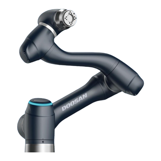
Doosan A0509 Quick Manual
Hide thumbs
Also See for A0509:
- Installation manual (137 pages) ,
- Programming manual (392 pages) ,
- User manual (253 pages)
Advertisement
Quick Links
Robot Arm (A0509/A0509s
Payload within Work
Radius
Max. Work Radius
TCP Speed
Position Repeatability
(ISO 9283)
Weight
Protection Rating
Digital I/O - Flange
Power supply -
Flange
*
)
5 kg
900 mm
Over 1 m/s
± 0.03 mm
21 kg
IP 54
2 In, 2 Out, RS485
DC 24 V, 2A (Max. 3A)
*Model with Force Torque Sensor
Doosan Robot
A0509 | A0509s | A0912 | A0912s
Quick Guide
Control Box
450x210x265 mm + Stand100 mm
Size
Weight
13 kg
Protection Rating
IP 40
Digital I/O
16 In, 16 Out
Analog I/O
2 In, 2 Out
I/O Power supply
DC 24 V
Rated voltage
100-240 (50~60Hz) VAC
Ethernet (TCP/IP), USB 3.0
Interface
(RS232/422/485*)
*USB to RS232/422/485 converter required
Advertisement

Summary of Contents for Doosan A0509
- Page 1 Doosan Robot A0509 | A0509s | A0912 | A0912s Quick Guide Robot Arm (A0509/A0509s Control Box Payload within Work 450x210x265 mm + Stand100 mm 5 kg Size Radius Max. Work Radius 900 mm Weight 13 kg TCP Speed Over 1 m/s...
- Page 2 Please be sure to refer to the detailed manual for product installation, use and precautions. ◼ Doosan Robotics does not assume responsibility for any damages or losses that occur during transportation. ◼ Configure the DIP switch according to components and additional components before connecting and starting up the product.
-
Page 3: Component Check
Component Check Robot (including connection cables)* Control Box* Emergency stop Button* Control Box Power Cable* Teach Pendant** Smart Pendant** Note Items are indicated as standard items (*) and optional items (**, sold separately). The laptop is not included in the package, and it is necessary when installing the DART-Platform. ... - Page 4 Emergency Stop Button Setting Switch Configure the emergency stop button setting switch on the Case according to components and additional components before connecting and starting up the product. Emergency Stop Button Setting Switch 1.Teach Pendant(O), Smart Pendant(O) 2.Teach Pendant(O), Emergency Stop Case 1 Button(O) 3.All use...
-
Page 5: Installation
Transportation Cautions during Transportation ※ When relocating the robot, have two or more individuals hold the link area of the robot. ※ The control box is moved by grasping the side handle. Installation Cautions during Installation ※ Before installing the robot, secure sufficient space and install the robot on a firm, even surface. ※... - Page 6 Emergency Stop Function In emergency situations, press the Emergency Stop button or the Emergency Stop located on the top right of the teach pendant or smart pendant to immediately stop the system. ※ SS1 stop mode is set as the default setting of the emergency stop button. ※...
- Page 7 Booting If you use standard items, you should install DART-Platform SW for robot control. Please install DART-Platform in advance. The installer download can be found in Robot LAB > Resources > (https://robotlab.doosanrobotics.com/en/MyRobot/Dashboard Software ). To download the installer, you need to log in the Robot LAB. ※...
- Page 8 Note The boot status is identified by the robot LED illuminated. If there is no connection between the control box and DART-Platform, change the C class band of IP address and default gateway of the desktop or laptop with DART-Platform installed to the C class band of the control box’s IP address, and retry.
- Page 9 The copyright and intellectual property rights of the contents of this manual are held by Doosan Robotics. It is therefore prohibited to use, copy, or distribute the contents without written approval from Doosan Robotics. In the event of abuse or modification of the patent rights, the user will be solely responsible for the consequences.


Need help?
Do you have a question about the A0509 and is the answer not in the manual?
Questions and answers