Doosan M0609 User Manual
Hide thumbs
Also See for M0609:
- Programming manual (392 pages) ,
- User manual (253 pages) ,
- Reference manual (202 pages)
Table of Contents
Advertisement
Quick Links
Advertisement
Table of Contents

Related Manuals for Doosan M0609


Summary of Contents for Doosan M0609
- Page 1 Manual Version 1.9 Software Version 2.5...
-
Page 2: Table Of Contents
3.3 Booting and Disengaging Packing Position ..........32 3.3.1 System Booting ................................32 3.3.2 Disengaging Packaging Pose ..........................33 3.4 Robot Mode and Status ..................35 3.4.1 Manual Mode ................................35 3.4.2 Auto Mode ..................................35 Doosan Robotics User Manual v1.9... - Page 3 3.4.3 Status and Flange LED Color for Each Mode ....................36 3.5 Robot Safety Setting ..................38 3.5.1 Safety Limit Setting ..............................38 3.5.2 Work Area Setting ............................... 38 4. Manual Robot Operation ............39 4.1 Jog Operation..................... 39 4.2 Hand-Guiding Operation .................. 39 4.2.1 Teach Pendant Hand-Guiding Button ........................
- Page 4 8.2 Task Builder Commands ................106 8.3 Deprecated Skill Command ................109 8.4 Edit Task ......................110 8.4.1 Edit Task Screen Configuration ..........................111 8.4.2 Add Command ................................112 8.4.3 Delete Command ..............................112 8.4.4 Paste command ................................ 112 Doosan Robotics User Manual v1.9...
- Page 5 8.5 Setting and Applying Command Properties ..........114 8.6 Motion Command Property Setting ............. 115 8.6.1 Waypoint Setting ............................... 115 8.6.2 Speed Setting ................................115 8.6.3 Operation Mode Setting ............................116 8.6.4 Blending Mode Setting ............................116 8.6.5 Multi-Segment (Waypoint) Setting ........................116 8.7 Skill Command Property Setting ..............
- Page 6 12.3.1 Robot Home Position Setting ..........................169 12.3.2 Cockpit Setting................................169 12.3.3 Remote Control Setting ............................169 12.3.4 Process Button Setting ............................170 12.4 Change and Disable Password ..............173 12.5 User Role Setting ..................... 174 12.6 Network Setting ....................175 Doosan Robotics User Manual v1.9...
- Page 7 12.6.1 Modbus TCP/RTU Setting............................. 175 12.6.2 ModbusTCP Master Setting ..........................176 12.6.3 ModbusRTU Master Setting ..........................176 12.7 System Update ....................177 12.7.1 Update ..................................177 12.7.2 System Restore ................................. 178 12.8 Check and Enter Robot License Code ............179 12.9 Check Log ......................
-
Page 8: Preface
The copyright and intellectual property rights of the contents of this manual are held by Doosan Robotics. It is therefore prohibited to use, copy, or distribute the contents without written approval from Doosan Robotics. In the event of abuse or modification of the patent right, the user will be fully responsible for the consequences. -
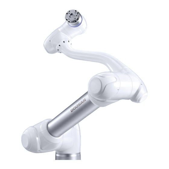
Page 9: Product Introduction
Product Introduction Robot Overview 1.1.1 Names of Each Part Name Name Base Link2 Link1 Tool Flange... -
Page 10: Key Features
“3.4.3 Status and Flange LED Color Flange LED for Each Mode.” I/O port for tool control. Flange I/O (Digital input 3ch, output 3ch) Connector Used for supplying power to and communication of the robot. Doosan Robotics User Manual v1.9... - Page 11 Item Description [Option] Controller used for direct teaching. Cockpit Area to install tools. Tool Flange I/O port for tool control. Flange I/O (Digital input 2ch, output 2ch) Displays the robot status with different colors. For more information about robot status, refer to the “3.4.3 Status and Flange LED Color LED (1-axis) for Each...
-
Page 12: Control Box Overview
Used to turn ON/OFF the main power of the control box. Power switch Robot cable Used to connect the robot cable to the control box. connection terminal Power connection Used to connect the control box power supply. terminal Doosan Robotics User Manual v1.9... - Page 13 Item Description I/O connection terminal Used to connect the control box or peripherals. (internal) Emergency stop button Connects the emergency stop button or smart pendant cable and smart pendant to the control box. connection terminal Teach pendant cable Used to connect the teach pendant cable to the control box. connection terminal Robot cable connection Used to connect the robot cable to the control box.
-
Page 14: Teach Pendant Overview
Hand-Guiding Press and hold the button to move the robot freely into a desired button pose. ※ The teach pendant is not a standard item but an optional item, so it must be purchased separately Doosan Robotics User Manual v1.9... -
Page 15: Smart Pendant (A-Series)
1.4 Smart Pendant (A-Series) Item Description Used to indicate the robot status by displaying the same color as the Robot LED robot status LED to the user. Used to indicate whether the system entered smart pendant mode. Device LED When four input signal buttons (F1 to F4) are pressed, the LED lights Function LED up and indicates the press status There are a total of 11 buttons including four input signal buttons (F1-... -
Page 16: Emergency Stop Button (A-Series)
1.5 Emergency Stop Button (A-Series) Item Description Emergency Stop In case of an emergency, press the button to stop robot operation. Button: Doosan Robotics User Manual v1.9... -
Page 17: System Configuration
System Configuration Power Command/ Supply/ Monitoring Network Teach pendant Control box Robot • Teach Pendant: It is a device that manages the overall system, and it is capable of teaching the robot specific poses and setting robot and control box related settings. •... - Page 18 Emergency Stop Button: If a laptop is used as part of the system, it acts as the emergency stop ㅇ ㅇ button of the teach pendant. ㅇ ㅇ ㅇ • Robot: It is an industrial collaborative robot that can perform transport or assembly tasks with various tools. ㅇ ㅇ ㅇ ㅇ ㅇ Doosan Robotics User Manual v1.9...
-
Page 19: Safety
Safety Safety Indications of User Manual Failure to observe instructions with this symbol may result in serious Danger accidents that could result in death or serious injury to the operator. Failure to observe instructions with this symbol may result in accidents that Warning cause severe injury to the operator. -
Page 20: Precautions For Use
Do not put fingers inside the control box with power supplied. Live cables are connected, which may lead to electrocution or injury. • Do not modify the robot. Doosan Robots is not responsible for for any issues that occur due to unauthorized modification. •... - Page 21 • For information about additional modules, refer to corresponding manuals.
-
Page 22: Types Of Stop Modes For Safety
If the robot end (TCP) is within the Collaborative Workspace and if the Nudge function is enabled, the user can apply force to the robot directly (Nudge) to restart work. For more information, refer to “7.4.12 공동 작업 공간 설정하기” Doosan Robotics User Manual v1.9... -
Page 23: Emergency Stop
Emergency Stop In emergency situations, press the Emergency Stop button on the top right of the teach pendant to immediately stop the system. • Twist the Emergency Stop button clockwise to disengage the emergency stop condition. - Page 24 • If an emergency stop occurred through the port set at Safety I/O, the button capable of accessing the screen for Safety Input setting at the bottom of the emergency stop popup window is enabled. Doosan Robotics User Manual v1.9...
-
Page 25: Other Safety Functions
Other Safety Functions The system offers Safety Recovery Mode and Zero-Gravity Motion for user safety and robot recovery. • Safety Recovery Mode: If there is an error with a continuing safety violation or if a robot is to be packed, the user can use Safety Recovery Mode to configure the position and angle of the robot. For more information about Safety Recovery Mode, refer to “10.7 Safety Recovery Mode.”... -
Page 26: System Power Cut-Off
A power switch is installed on the bottom of the control box to cut off system power. Before cleaning or servicing the robot or control box, or before disassembling the system, cut off system power using the power switch. Doosan Robotics User Manual v1.9... -
Page 27: Starting Up The Robot
Starting Up the Robot System Power-Up Press and hold the power button on the upper left of the teach pendant. • The power for systems such as the robot, control box and teach pendant is turned on. • To turn off the power, press and hold the button again. Note If the system does not power up, check the power switch at the bottom of the control box. - Page 28 Press the power button at the bottom of the control box. • The power for systems such as the robot, control box, teach pendant and smart pendant is turned on. [PC Power ON/OFF only when Doosan Robotics User Manual v1.9...
- Page 29 E-STOP Box is used - Standard Item] Open the control box door, and press and hold the power button located below the bottom right of the Safety board. • To turn off the power, press and hold the button. ON/OFF Switch [PC Power ON/OFF when Teach Pendant is used - Optional Item] Press and hold the power button located on the top left of the teach pendant.
- Page 30 Press and hold the power button on the upper left of the smart pendant. • To turn off the power, press and hold the button again. Note If the system does not power up, check the power switch at the bottom of the control box. Doosan Robotics User Manual v1.9...
-
Page 31: Dip Switch Setting (A-Series)
DIP Switch Setting (A-Series) Configure the DIP switch on the Case according to components and additional components before connecting and starting up the product. If the setting is not configured according to the guide, the robot will not operate properly. The DIP switch is located on the bottom left of the board inside the control box door (refer to below). -
Page 32: Booting And Disengaging Packing Position
The DART Platform displays a screen that shows the robot connected to the network after booting, and the process of checking the robot’s serial number and connecting to the robot take place on this screen. Doosan Robotics User Manual v1.9... -
Page 33: Disengaging Packaging Pose
3.3.2 Disengaging Packaging Pose The robot is in its packaging pose to allow easy transportation or packaging. To use the robot, it is necessary to disengage the packaging pose. Disengaging Packaging Pose: Tap Status on the initial screen of the teach pendant. Tap the Safety Recovery button. - Page 34 The robot status display on the bottom right of the screen changes from Recovery to Standby. The robot is now in a state where the user can operate it. Press the Close button on the Status screen to close the status window. Doosan Robotics User Manual v1.9...
-
Page 35: Robot Mode And Status
Robot Mode and Status The operation modes of the robot consist of Manual Mode, where the user controls the robot directly, and Auto mode, where the robot operates without direct user control. 3.4.1 Manual Mode This is the mode in which the robot operates according to direct user control. The robot only operates when a button related to an action is pressed, and releasing the button results in stopping the corresponding action. -
Page 36: Status And Flange Led Color For Each Mode
Others Backdrive (M-Series) robot to be pushed by hand. LED Off (A Series) Use caution, as the axis will not lock by itself and will fall if the brake is not engaged again. Doosan Robotics User Manual v1.9... - Page 37 Mode Status Description Flange LED The Teach Pendant UI is in the actual mode execution screen in a single work space. Pressing the "Execute" button will execute the task Auto White / Green Ready program. White is displayed for a single work space and green is displayed for a collaborative work space.
-
Page 38: Robot Safety Setting
Settings of the main menu. For more information about the tool direction change limit section, refer to “7.4.19 Tool Direction Change Limit Section Setting” Doosan Robotics User Manual v1.9... -
Page 39: Manual Robot Operation
Manual Robot Operation Jog Operation The robot can be operated manually using the Jog function on the teach pendant. For more information about the jog function, refer to “11 Jog Function.” Hand-Guiding Operation The user can change the robot’s pose by directly moving the robot. Use the Hand-guiding button on the teach pendant or use the cockpit located on joint J6 to change the robot’s pose. -
Page 40: Cockpit Button (Five Buttons)
Axis Lock: Changes the pose according to the Z-axis of the User Setting Button tool coordinates Surface Lock: Changes the pose according to the X-Y surface Doosan Robotics User Manual v1.9... - Page 41 Item Description of the tool coordinates Point Lock: Changes the angle only from the reference point of the tool coordinates Angle Lock: Changes the position only with the current TCP angle locked For more information about the settings, refer to “12.3.2 Cockpit Setting.”...
-
Page 42: Cockpit Button (Six Buttons)
Axis Lock: Changes the pose according to the Z-axis of the tool coordinates User Setting Button Surface Lock: Changes the pose according to the X-Y surface of the tool coordinates Doosan Robotics User Manual v1.9... - Page 43 Item Description Point Lock: Changes the angle only from the reference point of the tool coordinates Angle Lock: Changes the position only with the current TCP angle locked For more information about the settings, refer to “12.3.2 Cockpit Setting.”...
-
Page 44: Robot Teaching And Execution
Manager, which allows the user to easily create and execute task programs. Task Writer uses DRL (Doosan Robot Language) to create and execute programs suited for the user’s process, and it also features a Custom Code function where the user can load and execute task programs created by referring to the Programming Manual. -
Page 45: System Operation Program Outline
System Operation Program Outline The UI of the system operation program consists of the following: Item Description This area displays the name of the task currently being executed and Status Display the current work status. Area This area is where the user enters and changes settings when performing work using the robot. -
Page 46: Status Display Area
Pressing the Workcell Manager, , Task Builder or or Task Writer button on the main menu without closing the popup window using the button on the Status, Jog or Settings screen will enter a new screen rather than returning to the previous screen. Doosan Robotics User Manual v1.9... -
Page 47: Main Menu
Main Menu Major functions of the system can be checked in the main menu. Tap each menu button to go to the corresponding menu screen. • Home: It is the initial screen of the system, and information and a work progress graph of the current task are displayed. - Page 48 When transferring control between Windows and Teach Pendant from the same screen, the information saved on one screen is not automatically reflected in the other device until reloading is performed. Doosan Robotics User Manual v1.9...
-
Page 49: Home Screen Overview
Home Screen Overview Information about the current task status and task, and work progress graphs are displayed. Item Description The total number of lines of the task program is displayed. Tapping the number indicating the program line will go to Task Builder or Task Writer. - Page 50 Item Description Displays the target number, work count, and time of the current task. The Work Status information displayed can be selected using checkboxes. Doosan Robotics User Manual v1.9...
-
Page 51: Task Execution And Stopping
Task Execution and Stopping Tap the Execute button on the Home screen to view, execute or stop tasks. Item Description The total number of lines of the task program is displayed. Start/Pause Task Tap the Execute button to execute or pause the task. Task Information The command the robot is executing repeatedly can be checked. -
Page 52: Load Saved Tasks
A list of tasks saved on the system is displayed on the screen right. Tap the task to execute from the list. Moves to the screen to check and execute tasks. Note At first start-up of the system, the list is empty. Doosan Robotics User Manual v1.9... -
Page 53: Tool Setting
Tool Setting It sets the tool center point, weight and shape, which act as the basis for robot movement. It is possible to set and enable multiple end effectors and the tool center point, weight and shape on the Workcell Manager screen, so the tool center point, weight and shape of the end effector to be used must be set in Tool Settings of the tool. - Page 54 Press the Setting button to save the tool center point, weight or shape of the corresponding Workcell item. Note The robot’s tool center point and tool weight can be set to default where no input is made by pressing the Reset button. Doosan Robotics User Manual v1.9...
-
Page 55: Workcell Manager
Workcell Manager What is a Workcell Item? Workcell Item refers to the robot and all peripherals used together with the robot. Workcell items can be configured in the Workcell Manager screen before use. Also, the *Workcell Manager* can set commands for peripherals and can configure commands for the robot to perform certain patterns and actions. - Page 56 Workcell item select Item Button screen of the corresponding category. Note Detailed explanations of various Workcell items provided by the Workcell Manager are provided in a reference manual. Doosan Robotics User Manual v1.9...
-
Page 57: Add Workcell Item
Add Workcell Item Tap the add button at the bottom of each Workcell displayed on the initial screen of the Workcell Manager to display the Workcell category and type selection screen. Select the Workcell category and type to register, and tap the Select button to go to the corresponding Workcell setting screen. -
Page 58: Deprecated Workcell Item
Deprecated Workcell Items cannot be added, but they can be used to view setting information and can also be used in the current task program. If a deprecated Workcell Item is selected, the setting information of the Workcell Item is displayed along with a message stating “Deprecated Item.” Doosan Robotics User Manual v1.9... - Page 59 Tapping the Edit button cannot edit the setting, but deletion is possible.
-
Page 60: Robot Setting
Rotate or move the simulation screen. Tap the button and drag or tap the screen to control. Simulator Sets the direction of the simulator. The simulation is displayed Direction Setting from the selected direction. Work Space Displays the work space of the Workcell. Doosan Robotics User Manual v1.9... - Page 61 Item Description Delete Deletes the current Workcell. Confirm Saves the Workcell settings.
-
Page 62: World Coordinates Setting
Add button on the Robot Workcell and select Robot>World Coordinates. Tap the Edit button at the top. Please refer to the figure depicting the relationship between the World Coordinate and Base Coordinate, as well as related precautions. Doosan Robotics User Manual v1.9... - Page 63 Warning When changing the relationship between World and Base coordinates, the teaching point of World Coordinates or user coordinates based on World Coordinates can change. Changes are only recommended when the actual relationship between World Coordinates and Base Coordinates are changed. The mounting pose (installation inclination) is displayed on the right center.
-
Page 64: 7.4.2 Robot Limits Setting
The limit and initial safety settings may vary according to the robot lineup. Safety limits is the condition where the safety-rated monitoring function triggers the stop function. When stop is completed, the position of the robot and force applied externally may differ from the configured safety threshold. Doosan Robotics User Manual v1.9... - Page 65 TCP/Robot Limits To set the TCP/Robot Limits, go to the Robot Workcell and select Robot>Robot Limits > TCP/Robot. The TCP/Robot Limits setting screen layout is composed as follows: Item Description Force (N) It can limit the force level applied to the tool center point (TCP). Power (W) It can limit the mechanical power level of the robot.
- Page 66 The Joint Speed Limits setting screen layout is composed as follows: Item Description Joint Speed It can limit the speed of each joint. Default Value It resets the Joint Speed Limits settings to default values. Confirm It saves the current Workcell. Doosan Robotics User Manual v1.9...
- Page 67 Joint Angle Limits To set the joint angle limits, go to the Robot Workcell and select Robot>Robot Limits > Joint Angle. The Joint Angle Limits setting screen layout is composed as follows: Item Description Angle Range of It can limit the angle range of each joint. each Joint Default Value It resets the Joint Angle Limits settings to default values.
-
Page 68: 7.4.3 Safety I/O Setting
High: If the robot is set to Protective Stop by the safety input signal, it automatically restarts the program without restarting it with the Teach Pendent. Low: Runs SS2 (Safety Stop 2) Stop Mode if the program is being executed Doosan Robotics User Manual v1.9... - Page 69 Dynamic Zone Enable (H) It is available when dynamically activating the temporary disable collision section. High: If safety input is registered during temporary disable collision section setting, it activates the temporary disable collision section. Low: If safety input is registered during temporary disable collision section setting, it deactivates the temporary disable collision section.
- Page 70 Emergency Button is pressed, or self- diagnosis defect is detected during Remote Control Mode. High: Normal operation Low: Emergency stop required High: Task is in operation Task Operating Low: Task is not in operation Doosan Robotics User Manual v1.9...
-
Page 71: 7.4.4 Safety Stop Modes Setting
7.4.4 Safety Stop Modes Setting The safety-rated monitoring function can detect limit violations and set the stop mode used when stopping the robot. For more information about Stop Mode, refer to “2.3 Types of Stop Modes for Safety.” To set Safety Stop Modes, go to the Robot Workcell and select Robot>Safety Stop Modes. •... -
Page 72: Robot Installation Pose Setting
Auto Calculate is not supported in models without Force Toque Sensors. Doosan Robotics User Manual v1.9... -
Page 73: Tool Shape Setting
7.4.6 Tool Shape Setting To set the robot tool shape, tap the Add button on the Robot Workcell and select Robot>Tool Shape. The Safety Password is required during setup. Tool shape can be set by adding Cuboid, Sphere, and Capsule shapes. Select a shape that matches the tool and tap the Confirm button. -
Page 74: Tool Weight Setting
Note that safety monitoring functions are disabled during Auto Calculate. During Auto Calculate, the Auto Calculate button becomes the Stop button, which allows the user to stop Auto Calculate. If calculation is stopped, the weight and center of gravity values are reset. Doosan Robotics User Manual v1.9... - Page 75 A-Series does not feature Auto Calculate for weight.
-
Page 76: User Coordinates Setting
World Coordinates, and User Coordinates can be selected when teaching and moving using the robot from Task Builder and Task Writer. To set User Coordinates, tap the Add button on the Robot Workcell and select Robot>User Coordinates. Doosan Robotics User Manual v1.9... - Page 77 Enter the values required for settings. Make sure to read the description image and cautionary items of the User Coordinates. User Coordinates can be created based on 1-point, 2-points and 3-points. It is possible to load pallet coordinates from Advanced Options and apply them to User Coordinates points.
-
Page 78: Nudge Setting
(nudge force) and the standby time from nudge recognition and until the resuming the work (delay time) can be entered additionally. A-Series, which does not feature a Joint Toque Sensor, does not have Nudge settings in Advanced options. Doosan Robotics User Manual v1.9... -
Page 79: Robot Operation Environment Types
7.4.10 Robot Operation Environment Types The shape and settings related to the robot operation environment are as follows: Item Description The robot operation environment is set as a cuboid shape. Enter the lower endpoint (Point 1) and upper endpoint (Point 2) of the cuboid and tap the Save Pose button. - Page 80 Select X and Y coordinates to set the direction of the plane and tap the Save Pose button. Up to six planes can be configured. Enter the lower endpoint and upper endpoint of the polyhedron and tap the Save Pose button. Polyhedron (삭제 예정) Doosan Robotics User Manual v1.9...
- Page 81 Item Description The robot operation environment is set as a sphere shape. To configure the radius, enter the positions of the center point and endpoint of the sphere, and to configure the diameter, enter the two endpoints of the sphere, and tap the Save Pose button.
-
Page 82: Robot Work Space Setting
Space>Cuboid, Cylinder, or Polyhedron type. Enter the Workcell Name in the Workcell Name field on the top of the Workcell Setting screen. Enter the pose information according to the work space. Tap the Confirm button. Doosan Robotics User Manual v1.9... -
Page 83: Collaborative Work Space Setting
7.4.12 Collaborative Work Space Setting To configure the collaborative work space, tap the Add button on the Robot Workcell and select Collaborative Work Space>Collaborative Work Space. The Safety Password is required during setup. Separate the space into one or two planes consisting of X and Y axis coordinate information. Place the robot TCP on a point on the first line to designate. - Page 84 With nudge input, the force to be recognized (nudge force) and the standby time from nudge recognition and until the resuming the work (delay time) can be entered additionally. A-Series, which does not feature a Joint Toque Sensor, does not have Nudge settings in Advanced options. Doosan Robotics User Manual v1.9...
-
Page 85: Protection Section Setting
7.4.13 Protection Section Setting To configure the protection section, tap the Add button on the Robot Workcell and select Protection Area>Cuboid, Multi-angular Prism or Sphere type. The Safety Password is required during setup. Enter the Workcell Name in the Workcell Name field on the top of the Workcell Setting screen. Enter the pose information according to the set geometry type. -
Page 86: Disable Collision Detection Section Setting
If a LOW signal input is made, the disable collision detection section is disabled, enabling collision detection check. Tap the Confirm button. Doosan Robotics User Manual v1.9... -
Page 87: Space Limit Setting
7.4.15 Space Limit Setting To set space limits of the robot, tap the Add button on the Robot Workcell and select Space Limit>Cube, Cylinder, Multi-plane Box, Sphere or Tilted Cube type. The Safety Password is required during setup. Enter the Workcell Name in the Workcell Name field on the top of the Workcell Setting screen. Set the pose information according to work space, Valid Space, and Section Margin. -
Page 88: Collision Sensitivity Reduction Section Setting
Set the pose information according to work space, Valid Space, and Section Margin. To import shape settings configured from a different area, select a different Workcell item from Import Shape and Property of Advanced Options and press Import to import settings. Doosan Robotics User Manual v1.9... - Page 89 Set the Priority Option, Override Option, Tool Center Point/Robot Limit, Safety Stop Mode, TCP Direction Limit, Enable Dynamic Section, Nudge Option, Joint Angle Speed Limit and Joint Angle Limit in the Properties tab and press Confirm Press the activate toggle button to apply the custom section.
-
Page 90: End Effector Setting
Sets the tool center point (TCP) of the end effector. Checks and sets the output signal. Output Signal: Sets the output signal type (control box, flange, Output Signal Modbus). Name: Displays the output signal name. Doosan Robotics User Manual v1.9... - Page 91 Item Description Port Number: Select the end effector output signal port. Operation: Tests the output signal status. Checks and sets the input signal. Input Signal: Sets the output signal type (control box, flange, Modbus). Name: Displays the output signal name. The signal can be turned on Input Signal or off by pressing the toggle button.
-
Page 92: End Effector I/O Signal Setting
Enter the Workcell name in the Workcell Name field at the top of the Workcell Setting screen. Connect the end effector port to the robot flange or control box. Select the I/O signal type and select the I/O port number. Tap the Confirm button. Doosan Robotics User Manual v1.9... -
Page 93: End Effector I/O Testing
7.5.3 End Effector I/O Testing To test the operation status of the connected end effector, follow the procedure below. Select the end effector to test and tap the Edit button. Tap the Operate button to test the output signal. Check whether the end effector receiving the output signal operates normally. Note If the input signal is entered properly, a green indicator lights up. -
Page 94: Tool Rotation Angle (A, B, C) Within Tool Center Point Setting
Coordinate axis of “TCP Coordinate” (X,Y,Z): The coordinate axis is defined at the end of the tool installed on the end of the flange or working point. The rotation angle of the “TCP Coordinate” is defined based on the “Flange Coordinate” in the order of 1) to 3) of the following: Doosan Robotics User Manual v1.9... - Page 95 Z’ 1) Rotated by A 2) Rotated by B Z” along Axis - Z along Axis - Y X’ Y” Y’ X” Flange Coord. 3) Rotated by C along Axis - Z” TCP Coord. 1) Rotate A degrees along the z axis of the Flange Coordinate 2) Rotate B degrees along the y’...
-
Page 96: Tool Center Point Setting Based On Other End Effectors
Configure the tool Z-axis rotate angle of the configuring end effector and reference end effector. Click the Auto Calculate button on the bottom, check whether the calculated TCP is automatically entered and tap the Confirm button. Doosan Robotics User Manual v1.9... - Page 97 Note The configuring end effector and base end effector must be symmetrical on the tool Z axis.
-
Page 98: Machine Tool Setting
Machine mold and forms it into the desired shape. Machine Machine tool settings are similar to those of the gripper settings. For more information about each machine tool setting, refer to the separate manuals provided. Doosan Robotics User Manual v1.9... -
Page 99: Peripheral Setting
Peripheral Setting Peripherals are Workcell items that are not categorized as a robot, end effector or machine tool, but interact with the robot. Peripherals that can be registered in the Workcell Manager are as follows: Category Type Description This is a device that supplies bolts to the end of a screwdriver Shooting Bolt Feeder using a tube and air pressure. - Page 100 Moves the robot to the coordinates entered below. Enter the Move coordinates below and press and hold the Move button. Reset Resets the robot coordinates to the default values. Delete Deletes the current Workcell. Confirm Saves the Workcell settings. Doosan Robotics User Manual v1.9...
-
Page 101: Others
Enter the number of rows and columns of pallets. Select the pallet pattern. Select the base coordinates of the pallet. Move the robot TCP to Point 1 of the pattern guide to the right side of the pallet pattern. Tap the Save Pose button in Point 1 of the Pallet Reference Point. ... -
Page 102: Task Builder
Task Builder After registering and configuring all Workcell items in the Workcell Manager, a program to execute the robot task must be created using commands or skills. With Task Builder, the user can create a new task, enter skills or commands, or create tasks using templates recommended by the system. -
Page 103: Save Task
Enter the name of the new task program in the File Name field. Tap the Confirm button. When a new task is created using a template, the task edit screen is displayed. For more information on how to edit a task, refer to “8.4 Edit Task” 8.1.3 Save Task To save an edited task, tap the... -
Page 104: Save Task On External Storage Device
To import a task saved on an external storage device, follow these steps: Connect the external storage device with the task file to the USB slot. Tap Import on the initial screen of Task Builder. Tap the Search button. Doosan Robotics User Manual v1.9... - Page 105 When the Search File window appears, select the task to import and tap the Confirm button. Tap the Import button on the bottom right. When the task file is saved on an external storage device, the Save Complete window appears. To load a task file saved on the system, refer to “8.5 Load Saved Tasks.”...
-
Page 106: Task Builder Commands
This is used to return to the first command of a repetition statement Continue (Repeat). Break This is used to exit the repeat execution command (Repeat). Exit This is used to end task execution. This is used to define a subroutine within the task. Doosan Robotics User Manual v1.9... - Page 107 This is used to branch according to a specific condition during task execution. Call Sub This is used to execute the defined subroutine. Thread This is used to define a thread within the task. Run Thread This is used to execute the defined thread. Kill Thread This is used to end thread execution.
- Page 108 In models without Force Toque Sensors, Rx, Ry and Rz values of Weight Measure, Nudge, Compliance commands, and A, B and C values of Force command are not supported. The Watch Process Button command provides functions to control conditions using the Function button of the Process button. Doosan Robotics User Manual v1.9...
-
Page 109: Deprecated Skill Command
Deprecated Skill Command Skill commands can be updated due to increased usability and additional motion improvements. If a skill command is updated, the existing skill command becomes deprecated, and it cannot be added or edited. Deprecated skill commands are displayed as dimmed icons. Deprecated skill commands cannot be added new, but can be used to view property information or be used in the current task program. -
Page 110: Edit Task
Safety Stop: The robot has stopped due to an error or safety issue, so stop the current work and check the robot. Emergency Stop: the robot has stopped due to the activation of the emergency stop button. Work Screen Area." Doosan Robotics User Manual v1.9... -
Page 111: Edit Task Screen Configuration
8.4.1 Edit Task Screen Configuration The edit task screen of Task Builder is structured as follows: Item Description Multi Select: Select multiple commands. Copy: Copies a command. Cut: Cuts a command. Paste: Pastes a copied or cut command. Edit Command ... -
Page 112: Add Command
When a confirmation window appears, tap the Confirm button. 8.4.4 Paste command To copy/cut and paste a command to the task list, follow these steps: Select command to copy or cut. Tap the Copy or Cut button on the command edit tool. Doosan Robotics User Manual v1.9... - Page 113 Select the location to paste the command. The copied/cut command is added to the next line of the selected location. Tap the Paste button on the command edit tool.
-
Page 114: Setting And Applying Command Properties
If necessary, comments for the command can be entered. • The properties of a command are applied only after the Confirm button is tapped. For more information about command properties, refer to the Reference Manual provided separately. Doosan Robotics User Manual v1.9... -
Page 115: Motion Command Property Setting
Motion Command Property Setting 8.6.1 Waypoint Setting To configure the waypoint of a command, follow these steps: Select the type (Absolute, Relative) of reference coordinate and coordinate value. Either use the jog function or perform direct teaching to move the robot to the desired position. Tap the Save Pose button to save the robot tool position. -
Page 116: Operation Mode Setting
The motion commands requiring two or more segments are referred to as “multi-segment motion commands.” The following is an example of configuring a Move SJ command. Tap Add Pose in command properties. Segment 1 is added to the bottom line of Move SJ command. Doosan Robotics User Manual v1.9... - Page 117 Either use the jog function or perform direct teaching to move the tool to the desired position. Tap the Save Pose button in segment properties to save the robot tool position. Repeat steps 1-3 to add segments.
-
Page 118: Skill Command Property Setting
Distance entered is automatically calculated for the Action Pose and moves to the corresponding point. Move to Action Pose: This is the point on the workpiece where the End Effector performs work. (e.g., *Picking Pose*, *Placing Pose*) Doosan Robotics User Manual v1.9... - Page 119 Move to Retract Pose: This is the point to pick up the workpiece and move it safely to another point. It is the -Z direction from the Approach Pose, and a different direction can also be selected. The Retract Distance entered is automatically calculated for the Action Pose and moves to the corresponding point.
- Page 120 Action End Pose is the point where the work ends. (e.g., *Door Open Skill* – *End Pose*, *Screw Drive Skill* – *End Pose*) Doosan Robotics User Manual v1.9...
-
Page 121: Compliance Control And Contact Check
With the Compliance Control and Contact Check functions, which is the unique force control technology of Doosan Robotics, it is possible to easily perform teaching without repeated operation for accurate point designation since it allows position deviation within a tolerance range between the workpiece and surrounding items during robot operation. -
Page 122: Skill Command Work Point Setting With Cockpit Buttons
For example, with the Pick skill command: Add a skill command from Task Builder and tap the added skill command. Perform direct teaching to the skill’s action pose to move the robot. Press the Save Pose button on the cockpit. Doosan Robotics User Manual v1.9... -
Page 123: Execute Task Program
Execute Task Program Provides descriptions of the play screen of Task Builder and screen configuration. The play screen offers the function to priorly check robot motion by executing the task virtually. Note Before closing the simulator/robot, make sure to press the "stop" button ( ) to stop the motion program. -
Page 124: Real Mode Screen: End Effector Information Tab
The real mode screen end effector information tab of Task Builder is structured as follows: Item Description Sets the robot test play mode. Real Mode ( Real mode: Operates an actual robot to test the task in the task list. Doosan Robotics User Manual v1.9... - Page 125 It is recommended to test the robot program by designating temporary waypoints outside another machine’s work space. Doosan Robotics is not responsible for damages that occur due to programming error or robot malfunctioning, as well as damage to the equipment.
- Page 126 In the case of models without Force Toque Sensor, the force (X, Y, Z) values are not monitored. Doosan Robotics User Manual v1.9...
-
Page 127: Real Mode Screen: I/O Information Tab
8.8.3 Real Mode Screen: I/O Information Tab The real mode play screen end I/O information tab of Task Builder is structured as follows: Item Description Sets the robot test play mode. Real mode ( Real mode: Operates an actual robot to test the task in the task list. ... - Page 128 It stops the current task. Execute/pause It executes or pauses the work in the task list. toggle button Time It displays the time spent on the corresponding command/skill. I/O information screen in A-Series only monitors 2 flange I/Os. Doosan Robotics User Manual v1.9...
-
Page 129: Execute Task
8.8.4 Execute Task It is possible to test the task being created by executing it. To execute a task, follow these steps: Select the Play tab. Tap the Real Mode ( ) button. Drag the speed slider to set the robot speed. Press to execute the task. -
Page 130: Task Writer
Task Writer is intended for advanced users familiar with program coding. It allows complex motions that cannot be executed with basic commands to be created using DRL (Doosan Robot Language) and Custom Code, which allows the user to load and execute programs created or saved on an external storage device. -
Page 131: Save Task On External Storage Device
9.1.4 Save Task on External Storage Device To save an opened task as on an external storage device, follow these steps: Connect an external storage device to the USB slot. Only external storage devices with FAT32 file systems can be used. Tap the Menu button and tap Export. -
Page 132: Export Task To External Storage Device
Connect the external storage device with the task file to the USB slot. Tap the Export on the Task Writer initial screen. The export popup window appears. Select the external drive to export the task and tap the "Confirm" button. Doosan Robotics User Manual v1.9... - Page 133 The Save As popup window appears. Enter the task name in the popup window and tap the "Confirm" button.
-
Page 134: Edit Task Program
Thread: Jobs to be performed simultaneously with MainSub can be added as a Thread, and when a Thread is added, a command can be added below the Thread. Motion commands cannot be added to a Thread. Doosan Robotics User Manual v1.9... -
Page 135: Task Writer Command
Task Writer Command The commands available in the Task Writer are Motion Commands, Flow Control and Other Commands, and Advanced Commands. • Motion Command: These are commands used to adjust or change the robot’s pose. Move J Used to move the robot to the target joint coordinates. Used to move the robot along a line towards the target work space Move L coordinate. - Page 136 Wait Motion command is complete. GlobalVariables This is used to add a Global Variable. • Advanced Commands: There is a command to execute Hand-guiding. Hand Guide This is used to execute direct teaching during task execution. Doosan Robotics User Manual v1.9...
- Page 137 Hand Guide This is used to execute direct teaching during task execution. This is used to delay task execution until Nudge (applying force to Nudge the robot) input. In models without Force Toque Sensors, Rx, Ry and Rz values of Weight Measure, Nudge, Compliance commands, and A, B and C values of Force command are not supported.
-
Page 138: Setting And Applying Command Properties
Setting and Applying Command Properties Configuring and applying the commands in Task Writer are identical to those of Task Builder. Doosan Robotics User Manual v1.9... -
Page 139: Execute Task Program
Execute Task Program The execution of task programs in Task Writer is identical to that of Task Builder. -
Page 140: Debug Screen
Toggle Button Restart button. Pause Button Temporarily pauses the current task execution. Stop button Suspends the current task. Stage by Stage Executes one command at a time while the task is paused. Doosan Robotics User Manual v1.9... -
Page 141: 10. Monitoring And Testing
10. Monitoring and Testing To check or test the I/O information, tap the Status button in the main menu. The Status window allows you to check the I/O information of devices connected to the control box and flange, and the Zero-Gravity Motion mode and Safety Recovery function can be executed. The Status window is a popup window, so it is possible to tap the Status button on the Home, Task Builder or Task Writer screen even during Auto mode to check I/O information. -
Page 142: Screen Layout
Displays encryption of the entire job space data registered to check whether the job space setup has been modified. Status Value Safety Setup Displays encryption of the entire safety data registered to check whether the safety setup has been modified. Status Value Doosan Robotics User Manual v1.9... -
Page 143: I/O Status Check
10.2 I/O Status Check 10.2.1 Control Box/Flange Digital Input Check Check the port number of the device connected to the control box or flange. The following is displayed depending on the digital input status of the corresponding number. If the digital signal is a high signal, the icon is displayed in light green. ... -
Page 144: Control Box Analog Output Setting
Press the drop-down list of the analog output of the control box to select the item to set. Analog output information of the selected item is displayed on the right side of the drop- down list. Modify the analog output value. Doosan Robotics User Manual v1.9... -
Page 145: I/O Test
10.3 I/O Test Item Description Displays the task currently being edited or executed. Current Task If changes are made to the task being edited, they must be saved in Save Task order to test the I/O device. It displays the port number used for testing the I/O device, and it is Port Number displayed when the signal is on. -
Page 146: Modbus Test
Displays the list of IPs/Ports of the slave set of the selected Modbus Slave type. When selected, it displays a list of corresponding signals. Displays a list of signals set on the selected slave. Input and output Signal List signals can be checked. Doosan Robotics User Manual v1.9... -
Page 147: Servo On
10.5 Servo On Servo On refers to the standby status where the robot arm can be operated by supplying power to joints. Pressing the emergency stop button or violating critical safety limits sets the Servo Off status. During servo off status, the power to joints is cut off, which results in the robot arm being unable to be operated, and Workcell Manager, Task Builder, Task Writer and Jog, which are related to robot arm operation, are disabled in the main menu. -
Page 148: Zero-Gravity Motion Mode
Move each joint back to the normal work range individually in sequential order. If Zero-Gravity Motion mode is executed, the system must be rebooted to resume normal work again. Use caution as temporary sagging may occur depending on the axis location in Zero-Gravity Motion mode. Doosan Robotics User Manual v1.9... -
Page 149: Safety Recovery Mode
10.7 Safety Recovery Mode If there is an error with a continuing safety violation or if a robot needs to be packed for transportation, the user can use the Safety Recovery Mode to configure the position and angle of the robot. •... -
Page 150: Using Software Recovery Mode
For more information about the cockpit buttons, refer to Using Cockpit Buttons (4.2.2). Changes made to the setting are reflected on the simulation window on the left in real time. When the setting is complete, tap the X button on the top left. Doosan Robotics User Manual v1.9... -
Page 151: Packaging Mode Setting
10.7.2 Packaging Mode Setting To configure the packaging mode, follow these steps: Tap the Safety Recovery button in the Status window. Select the Packaging Mode tab. Tap the Packaging Mode toggle button to enable Packaging Mode. Tap the Go to Packaging Pose button. ... -
Page 152: 11. Jog Function
11. Jog Function In Jog mode, the user can navigate the entire work space or set the operation space the user configured as the robot operation space. The movement angle of each axis can be limited according to the selected operation space and joint angle limit of the safety setting. To use the jog function, tap the Jog button on the main menu. -
Page 153: Jog Screen
11.1 Jog Screen It is possible to navigate based on the current robot position on the jog screen. Item Description It configures the joint as the reference coordinate for jog mode. Joint It configures the task as the reference coordinate for jog mode. Task Select an axis to move in jog mode. - Page 154 If the robot stops due to reaching the joint limit or if a collision is detected while moving the robot with jog mode, set the safety recovery mode and move the robot to be positioned within the joint angle limit. For more information about Safety Recovery Mode, refer to “10.7 Safety Recovery Mode.” Doosan Robotics User Manual v1.9...
-
Page 155: Execute Based On Joint
11.1.1 Execute based on Joint To adjust the angle based on the robot joint, follow these steps: Select the Joint tab on the Joint screen. Select the axis (J1-J6) to adjust the angle. Press and hold the Direction Button ( ) to adjust the angle of the corresponding axis. -
Page 156: Execute Based On Robot Base
Select the display coordinates to be used as the base and select the Base as the reference point of the task coordinates. Select the Base Coordinates to move. Press and hold the Direction Button ( ) to move the corresponding axis. Note Safety area does not apply in virtual mode. Doosan Robotics User Manual v1.9... -
Page 157: Execute Based On World Coordinates
11.1.3 Execute based on World Coordinates To move the robot based on World Coordinates, follow these steps: Select the Task tab on the Jog screen. Select the display coordinates to be used as World Coordinates and select World as the reference point of the task coordinates. -
Page 158: Execute Based On Robot Tool
Select Base or World as the display coordinates and set the Tool based on the reference point of the task coordinates. Select the Tool Coordinates to move. Press and hold the Direction Button ( ) to move the corresponding axis. Note Safety area does not apply in virtual mode. Doosan Robotics User Manual v1.9... -
Page 159: Movement Screen
11.2 Movement Screen The robot can be moved by target angle/coordinates on the Move screen. If the coordinates the robot must move to are known or if the robot must be moved up to coordinates in decimal points, it is possible to move the robot by entering coordinates. -
Page 160: Move With Base Reference Coordinates
To move the robot based on base coordinates, follow these steps: Select the Move tab and select the Task tab. Select Base as the display coordinates and select the Base tab. Configure the pose to move with reference to the base. Doosan Robotics User Manual v1.9... -
Page 161: Move With World Coordinates Reference Coordinates
Tap and hold the Move to Corresponding Pose button to go to the set coordinate. 11.2.3 Move with World Coordinates Reference Coordinates To move the robot based on World Coordinates, follow these steps: Select the Move tab and select the Task tab. Select World as the display coordinates and select the World tab. -
Page 162: Setting Screen
Item Description It aligns the TCP based on the Base/World axis and target Default Motion direction. Align with Target Aligns the TCP with the target. Align with Workcell Aligns the TCP with Workcell item. Item Doosan Robotics User Manual v1.9... -
Page 163: Alignment Based On Base Axis/World Axis
11.3.1 Alignment based on Base Axis/World Axis When the work item is positioned in the Base/World axis direction of the robot, it is possible to align the TCP on the workpiece before workpiece teaching. The teaching pose can be configured in line with the Base/World Coordinates axis, making it is easy to specify a teaching pose. -
Page 164: Go To Home
Tap the Save Pose button of Point 1. Point 2 and Point 3 are set in the same way. When settings are complete, a virtual vector area is set based on the three points. Doosan Robotics User Manual v1.9... -
Page 165: Alignment Based On Workcell Items
(Optional) To set the TCP direction and position together, press the "toggle" button of Point 4 , move the robot to the desired position and tap the "Save Pose" button. Tap and hold the Align Axis button to align the axis. ... - Page 166 Doosan Robotics User Manual v1.9...
-
Page 167: 12. Environment Setting
12. Environment Setting To configure environment settings related to the operation setting, tap the Settings button in the main menu. Note When the Task Builder and Task Writer screens are changed to the Play tab, the Settings button on the main menu is disabled. 12.1 Language Setting To set the UI language of the operation program, follow these steps:... -
Page 168: Date And Time Setting
If the system is accessed via Windows, the Date and Time setting function is not available, and the system automatically synchronizes with the date and time of Windows. Doosan Robotics User Manual v1.9... -
Page 169: Robot Setting
12.3 Robot Setting Configures the default pose and cockpit related functions. 12.3.1 Robot Home Position Setting Tap the Settings button on the main menu and select Robot Settings>Home Position. Select the User Home Position. Selecting Default Home Position sets the default. Move the robot to the desired position and tap the Save Pose button. -
Page 170: Process Button Setting
The Process Button dashboard screen is displayed and commands using Process Button become available. When the Process Button mode launches from Windows, the teach pendant screen also changes to the Process Button screen. Doosan Robotics User Manual v1.9... - Page 171 Item Description It is the tab that displays monitoring information necessary for Task Monitoring Tab executing the input signal and Task of Process Button. It is the tab that displays the log messages collected during task Log Tab execution. Process Button When the Process Button is connected to the controller, it is displayed as Checked (green).
- Page 172 Tool Shape Indicator Tool Shape information used by the current task Collision Collision threshold information Force Force information Digital / Flange I/O Digital / Flange I/O information information Close Button to close the Process Button mode. Doosan Robotics User Manual v1.9...
-
Page 173: Change And Disable Password
12.4 Change and Disable Password A password is required to enter a setting with a lock icon ( To change or disable the password of settings with a lock icon, follow these steps: Select [Password] - [Safety Password] in the Settings menu. Enter the current password of the program and tap the Confirm button. -
Page 174: User Role Setting
To change a user role, tap the User Role button. Note The initial administrator password is admin. The initial teaching engineer password is admin. If the User Role button is disabled, it operates in the same way as an administrator role. Doosan Robotics User Manual v1.9... -
Page 175: Network Setting
Select the network method and tap the Confirm button. 12.6.1 Modbus TCP/RTU Setting The Modbus Master of Doosan Robotics can be used for I/O expansion or data exchanges through connections with other devices. The Function Codes supported by Doosan Robotics are as follows:... -
Page 176: Modbustcp Master Setting
The registered Signal Name can be used to read or write values appropriate for the Signal Type of the corresponding Signal Address. The ModbusRTU Master function from Doosan Robotics allows the use of most functions previously provided by ModbusTCP Master in the same capacity. -
Page 177: System Update
12.7 System Update The current robot system version can be checked, and the system can be updated using an external storage device. 12.7.1 Update To update the system, follow these steps: Connect the external storage device with the update file to the control box. Tap the Settings of the main menu, and select Robot Update –... -
Page 178: System Restore
Select the Radio button of the version to be restored. The Restore button is enabled. Press the Restore button. Restart the system when restore is complete. If the system is accessed via Windows, the system restore function is not available. Doosan Robotics User Manual v1.9... -
Page 179: Check And Enter Robot License Code
12.8 Check and Enter Robot License Code The serial number and model number of the robot system can be checked, and the product license can be entered or checked. The serial number, model number and license are used for customer support services. -
Page 180: Check Log
System log messages of the robot can be checked. Search can be made in units of 1 month, and logs can be deleted. 12.9.2 Extract Log Logs created during robot operation can be saved on a USB storage media. Search can be made in units of 1 week. Doosan Robotics User Manual v1.9... -
Page 181: Factory Reset
12.10 Factory Reset Factory reset is a function used to delete all user data and logs saved on the robot. When factory reset is performed, the database, log files, Workcell Items and task files are deleted. Tap the Setting button on the main and select Factory Reset. Tap the Reset button. -
Page 182: Screen Saver Mode Setting
The default setting is Use Screen Saver. This configures the time required to elapse before entering the screen saver mode. Default: 5 minutes Minimum Time: 1 minute Maximum Time: 24 hours (1440 minutes) Tap the Confirm button. Doosan Robotics User Manual v1.9... -
Page 183: 12.12 Idle Servo Off
12.12 Idle Servo Off If the robot is idle for a certain amount of time, the robot is automatically set to the Safety Off state. The default value is 5 minutes, and the time can be changed to a time the user prefers. -
Page 184: 12.13 Friction Calibration
When the Auto Calculate of selected axes is complete, the friction calibration result is displayed on each axis. Successful results are displayed in green and failed results are displayed in gray. Tap the Confirm button. Doosan Robotics User Manual v1.9... -
Page 185: 12.14 Kt Smart Factory Setting Screen
12.14 KT Smart Factory Setting Screen This screen sets the KT Smart Factory function. Tap the Settings button and select KT Smart Factory. Enter values according to the validation of each item. Items required are IP address, port value, Device ID, Device Password, Gateway ID and transmission frequency. -
Page 186: 12.15 Backup & Restore
To restore data, follow these steps: Tap the Settings button and select Backup & Restore. Tap the Restore menu. Tap the Restore button and tap the bak file to restore. When restore is complete, restart the system. Doosan Robotics User Manual v1.9... -
Page 187: Annex A. Control Box For Agv
Annex A. Control Box for AGV A.1 Product Introduction A.1.1 Control Box Overview Item Description I/O connection Used to connect the control box or peripherals. terminal (internal) Used to turn ON/OFF the main power of the control box. Power switch Teach pendant cable connection Used to connect the teach pendant cable to the control box. -
Page 188: A.1.2 System Configuration
It features various I/O ports that allow the connection and use of various equipment and devices. • Robot: It is an industrial collaborative robot that can perform transport or assembly tasks with various tools. Doosan Robotics User Manual v1.9... -
Page 189: A.2 Safety
A.2 Safety A.2.1System Power Cut-Off A power switch is installed on the top of the control box to cut off system power. Before cleaning or servicing the robot or control box, or before disassembling the system, cut off system power using the power switch. - Page 190 Doosan Robotics User Manual v1.9...
Need help?
Do you have a question about the M0609 and is the answer not in the manual?
Questions and answers
how to change the controller battery