
Related Manuals for Honeywell VERSAFLOW SONIC 1000/TWS 9000


Summary of Contents for Honeywell VERSAFLOW SONIC 1000/TWS 9000
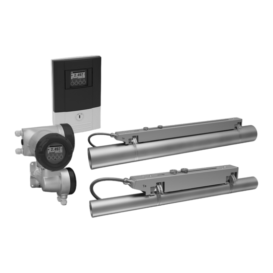
- Page 1 VERSAFLOW SONIC 1000/TWS 9000 VERSAFLOW SONIC 1000/TWS 9000 VERSAFLOW SONIC 1000/TWS 9000 VERSAFLOW SONIC 1000/TWS 9000 Handbook Handbook Handbook Handbook Ultrasonic clamp-on flowmeter for liquids ER 4.1.1_...
- Page 2 Copyright 2020 by Honeywell WARRANTY/REMEDY Honeywell warrants goods of its manufacture as being free of defective materials and faulty workmanship. Contact your local sales office for warranty information. If warranted goods are returned to Honeywell during the period of coverage, Honeywell will repair or replace without charge those items it finds defective.
- Page 3 Operation, and Troubleshooting of your device. Contacts Contacts Contacts Contacts World Wide Web: The following lists Honeywell’s World Wide Web sites that will be of interest to our customers. Honeywell Organization Honeywell Organization WWW Ad W Address (URL) dress (URL)
- Page 4 ABOUT THIS DOCUMENT VERSAFLOW SONIC 1000/TWS 9000 www.process.honeywell.com 34-VF-25-07 iss.2 GLO Nov 11 US...
-
Page 5: Table Of Contents
CONTENTS VERSAFLOW SONIC 1000/TWS 9000 1 Safety instructions 1.1 Software history ....................... 9 1.2 Intended use ........................10 1.3 Certification ........................10 1.4 Safety instructions from the manufacturer ..............11 1.4.1 Copyright and data protection ....................11 1.4.2 Disclaimer ..........................11 1.4.3 Product liability and warranty .................... - Page 6 CONTENTS VERSAFLOW SONIC 1000/TWS 9000 3.8.7 Installing the DOWN sensor rail in V-mode ................. 39 3.8.8 Installation of the DOWN sensor rail..................40 3.8.9 Find the transducer location with a fixed reference point ........... 40 3.8.10 Determine the transducer position with a paper roll............41 3.8.11 Installing the DOWN sensor rail in Z-mode ...............
- Page 7 CONTENTS VERSAFLOW SONIC 1000/TWS 9000 5.2 General instructions for programming................95 5.3 Function description installation menu ................. 96 5.4 Start measurement (standard setup) ................98 5.5 Start measurement of large version................99 6 Operation 6.1 Display and operating elements .................. 101 6.1.1 Display in measuring mode with 2 or 3 measured values ..........
- Page 8 CONTENTS VERSAFLOW SONIC 1000/TWS 9000 7.7.1 General information......................160 7.7.2 Form (for copying) to accompany a returned device............161 7.8 Disposal ........................161 7.9 Disassembly and recycling................... 162 7.9.1 Remove the connection and/or other cable(s) ..............163 7.10 Disassembling the sensor rail ................... 165 7.11 Overview of the sensor materials and components ..........
-
Page 9: Safety Instructions
SAFETY INSTRUCTIONS VERSAFLOW SONIC 1000/TWS 9000 1.1 Software history For all devices, the "Electronic Revision" (ER) is consulted to document the revision status of the electronics according to NE 53. It is easy to see from the ER whether any fault repairs or major changes to the electronic equipment have taken place and what effect they have had on compatibility. -
Page 10: Intended Use
SAFETY INSTRUCTIONS VERSAFLOW SONIC 1000/TWS 9000 1.2 Intended use CAUTION! Responsibility for the use of the measuring devices with regard to suitability, intended use and corrosion resistance of the used materials against the measured fluid lies solely with the operator. -
Page 11: Safety Instructions From The Manufacturer
SAFETY INSTRUCTIONS VERSAFLOW SONIC 1000/TWS 9000 1.4 Safety instructions from the manufacturer 1.4.1 Copyright and data protection The contents of this document have been created with great care. Nevertheless, we provide no guarantee that the contents are correct, complete or up-to-date. -
Page 12: Product Liability And Warranty
SAFETY INSTRUCTIONS VERSAFLOW SONIC 1000/TWS 9000 1.4.3 Product liability and warranty The operator shall bear responsibility for the suitability of the device for the specific purpose. The manufacturer accepts no liability for the consequences of misuse by the operator. Improper installation or operation of the devices (systems) will cause the warranty to be void. -
Page 13: Warnings And Symbols Used
SAFETY INSTRUCTIONS VERSAFLOW SONIC 1000/TWS 9000 1.4.5 Warnings and symbols used Safety warnings are indicated by the following symbols. DANGER! This warning refers to the immediate danger when working with electricity. DANGER! This warning refers to the immediate danger of burns caused by heat or hot surfaces. - Page 14 SAFETY INSTRUCTIONS VERSAFLOW SONIC 1000/TWS 9000 www.process.honeywell.com 34-VF-25-07 iss.2 GLO Nov 11 US...
-
Page 15: Device Description
DEVICE DESCRIPTION VERSAFLOW SONIC 1000/TWS 9000 2.1 Scope of delivery INFORMATION! Do a check of the packing list to make sure that you have all the elements given in the order. INFORMATION! Inspect the packaging carefully for damages or signs of rough handling. Report damage to the carrier and to the local office of the manufacturer. - Page 16 DEVICE DESCRIPTION VERSAFLOW SONIC 1000/TWS 9000 Figure 2-2: Additional items (depends on version) 1 Sensor with cable 2 4 fixing units 3 Coupling pads 4 2 metal straps 5 Optional: cable (splitter) box with signal cable (depends on ordered version) The underneath accessories can be ordered optionally: •...
-
Page 17: Device Description
DEVICE DESCRIPTION VERSAFLOW SONIC 1000/TWS 9000 2.2 Device description The ultrasonic clamp-on sensor rail is designed to be installed on the outside of the pipeline to measure the volume flow of liquids. The device is a combination of sensor rail(s) and an ultrasonic flow converter. -
Page 18: Field Housing (Remote Version)
DEVICE DESCRIPTION VERSAFLOW SONIC 1000/TWS 9000 2.2.1 Field housing (remote version) Figure 2-4: Construction of the field housing for remote versions 1 Cover for electronics and display 2 Cover for power supply and inputs/outputs terminal compartment 3 Cover for flow sensor terminal compartment... -
Page 19: Nameplates
DEVICE DESCRIPTION VERSAFLOW SONIC 1000/TWS 9000 2.3 Nameplates INFORMATION! Look at the device nameplate to ensure that the device is delivered according to your order. Check for the correct supply voltage printed on the nameplate. 2.3.1 Overview of the nameplates (examples) -
Page 20: Example Nameplate Of The Flow Sensor Rail
DEVICE DESCRIPTION VERSAFLOW SONIC 1000/TWS 9000 Example of the nameplate wall version Figure 2-8: Example of nameplate (wall version) 1 Name and address of the manufacturer 2 Type designation of the flowmeter and CE sign with manufacturing date 3 Disposal logo and supplier website... -
Page 21: Example Of Io Nameplate
DEVICE DESCRIPTION VERSAFLOW SONIC 1000/TWS 9000 2.3.4 Example of IO nameplate Electrical connection data of inputs/outputs (example of basic version) Figure 2-9: Nameplate inputs / outputs • A = active mode; the signal converter supplies the power for connection of the subsequent devices •... - Page 22 DEVICE DESCRIPTION VERSAFLOW SONIC 1000/TWS 9000 www.process.honeywell.com 34-VF-25-07 iss.2 GLO Nov 11 US...
-
Page 23: Installation
INSTALLATION VERSAFLOW SONIC 1000/TWS 9000 3.1 General notes on installation INFORMATION! Inspect the packaging carefully for damages or signs of rough handling. Report damage to the carrier and to the local office of the manufacturer. INFORMATION! Do a check of the packing list to make sure that you have all the elements given in the order. -
Page 24: Pre-Installation Requirements
INSTALLATION VERSAFLOW SONIC 1000/TWS 9000 3.4 Pre-installation requirements INFORMATION! To assure a quick, safe and uncomplicated installation, we kindly request you to make provisions as stated below. Make sure that you have all necessary tools available: • Allen key (4 and 5 mm) •... - Page 25 INSTALLATION VERSAFLOW SONIC 1000/TWS 9000 Specific for sensors rail(s) WARNING! Be careful when locking the rail back onto the mounting units as your fingers may get stuck • between rail and pipe it is mounted on. This may cause injury.
-
Page 26: Installation Conditions
INSTALLATION VERSAFLOW SONIC 1000/TWS 9000 3.7 Installation conditions 3.7.1 Inlet, outlet and recommended mounting area To perform an accurate flow measurement install the sensor rail(s) more then 10 DN of any possible downstream flow disturbance (e.g. elbow, valve, header, pump). Please follow the installation recommendations in the next installation position examples. -
Page 27: Horizontal (Long) Pipes
INSTALLATION VERSAFLOW SONIC 1000/TWS 9000 3.7.2 Horizontal (long) pipes Horizontal pipes are ideal to install a clamp-on, recommended orientation 45-90 degrees, refer Inlet, outlet and recommended mounting area on page 26. In cases that a full pipe condition is not guaranteed (or not possible): •... -
Page 28: T-Section
INSTALLATION VERSAFLOW SONIC 1000/TWS 9000 3.7.4 T-section Figure 3-4: Distance behind a T-section 1 ≥ 20 DN 3.7.5 Bends Figure 3-5: Installation in bending pipes (90°) INFORMATION! Recommended installation positions are at a lowered or ascending section of the pipeline installation. -
Page 29: Open Feed Or Discharge
INSTALLATION VERSAFLOW SONIC 1000/TWS 9000 Figure 3-6: Installation in bending pipes (45°) INFORMATION! Vertical installation on a descending slope in the pipeline is only recommended when the back- pressure is controlled. 3.7.6 Open feed or discharge Figure 3-7: Open feed or discharge Install the flowmeter on a lowered section of the pipeline to ensure a full pipe condition through the meter. -
Page 30: Position Of Pump
INSTALLATION VERSAFLOW SONIC 1000/TWS 9000 3.7.7 Position of pump Figure 3-8: Position of pump INFORMATION! Recommended position to install a flowmeter is downstream a pump (on a position where the flow disturbances of the pump are resolved) A clamp-on flowmeter can be installed in the suction line of a pump if there is no cavitation in the pipeline system. -
Page 31: Pipe Diameters And Sensor Rail(S) Construction
INSTALLATION VERSAFLOW SONIC 1000/TWS 9000 3.7.9 Pipe diameters and sensor rail(s) construction INFORMATION! Check the ordered rail(s) with the preferred measuring mode Figure 3-10: Measuring modes 1 Z-mode 2 V-mode 3 W-mode 4 X-mode 5 V-mode; large set rails Overview version and measuring modes... -
Page 32: Installation Of The Sensor Rail
INSTALLATION VERSAFLOW SONIC 1000/TWS 9000 3.8 Installation of the sensor rail 3.8.1 General mechanical installation Installation of the sensor rails with the metal straps Installation of the sensor rails with the metal straps Installation of the sensor rails with the metal straps Installation of the sensor rails with the metal straps •... - Page 33 INSTALLATION VERSAFLOW SONIC 1000/TWS 9000 Change the position of the transducer Change the position of the transducer Change the position of the transducer Change the position of the transducer • Depending on the distance and the pipe surface, release/unlock the sensor rail.
-
Page 34: Installation Of Solid Contact Material
INSTALLATION VERSAFLOW SONIC 1000/TWS 9000 3.8.2 Installation of solid contact material The coupling pads can optionally be used as solid contact material between the transducers and the pipe wall surface. Solid coupling pads will absorb some of the signal strength but are very stable over time. -
Page 35: Standard Installation Options
INSTALLATION VERSAFLOW SONIC 1000/TWS 9000 3.8.3 Standard installation options Single and dual path configuration Single path variants Figure 3-11: Overview of single path variants 1 1 path installed on 1 pipe (small or medium sensor rail) 2 1 path installed on 1 pipe (2 large sensor rails in V-mode) -
Page 36: Installation Instructions For Small And Medium Sensor Rail(S)
INSTALLATION VERSAFLOW SONIC 1000/TWS 9000 3.8.4 Installation instructions for small and medium sensor rail(s) Figure 3-13: Procedure for installation of small or medium sensor rail 1 Small sensor rail 2 Medium sensor rail 3 Choose for V-mode or ... 4 Choose for W-mode 5 Make settings in converter www.process.honeywell.com... -
Page 37: Mechanical Installation Of Large Version
INSTALLATION VERSAFLOW SONIC 1000/TWS 9000 3.8.5 Mechanical installation of large version INFORMATION! You need a calculator, measuring band and pen & paper to install a large version. The large sensor rail consists of an up and a down rail and has a transducer and a cable which has to be connected directly to the converter or via a cable (splitter) box. - Page 38 INSTALLATION VERSAFLOW SONIC 1000/TWS 9000 Figure 3-15: Installing large version sensor rail 1 Pull the metal strap through the upper slit of the UP sensor rail. 2 Take the metal strap around the pipe (45...60°). 3 Push the end of the metal strap into the lower slot of the fixing unit.
-
Page 39: Installing The Down Sensor Rail In V-Mode
INSTALLATION VERSAFLOW SONIC 1000/TWS 9000 3.8.7 Installing the DOWN sensor rail in V-mode The V-mode installation is based on a reflected path and can be used depending on the medium and pipe conditions. It can be applied for the large sensor rails up to DN2000/80”. The installation... -
Page 40: Installation Of The Down Sensor Rail
INSTALLATION VERSAFLOW SONIC 1000/TWS 9000 3.8.8 Installation of the DOWN sensor rail Measure the circumference of the pipe with a measuring band. For Z-mode, you must install the DOWN sensor rail at the opposite location on the pipe. The two most common ways to find the exact location are with the use of a fixed reference point or determination of transducer position with the use of a paper/plastic material roll. -
Page 41: Determine The Transducer Position With A Paper Roll
INSTALLATION VERSAFLOW SONIC 1000/TWS 9000 3.8.10 Determine the transducer position with a paper roll With the use of a paper (or plastic material) roll 1, the position of the transducers at the right position can be found. The next steps need to be followed: Step 1 •... - Page 42 INSTALLATION VERSAFLOW SONIC 1000/TWS 9000 Step 3 • Mark both ends A and B of the paper on the pipe • Mark one side of the length C of the paper, perpendicular to both A and B • Draw the axial lines 3 on the pipeline (from the top and bottom side of the paper roll). Use a...
-
Page 43: Installing The Down Sensor Rail In Z-Mode
INSTALLATION VERSAFLOW SONIC 1000/TWS 9000 3.8.11 Installing the DOWN sensor rail in Z-mode Figure 3-22: Finding the location for the DOWN sensor rail 1 Measure the distance between the transducer and the end of the UP sensor rail. 2 Advised distance as shown in menu X7.4 3 Determine and mark the location of the transducer of the DOWN sensor rail: 3 3 3 3 = 1 1 1 1 - 2 2 2 2 •... -
Page 44: Configuration Instructions For Large Sensor Rail(S)
INSTALLATION VERSAFLOW SONIC 1000/TWS 9000 3.8.12 Configuration instructions for large sensor rail(s) Figure 3-24: Procedure for installation of large version 1 Use the wizard of the signal converter (installation menu X1...X7.2.8) 2 Read the advised mounting distance in menu X7.2.3... -
Page 45: Installation Instructions For X Mode Configuration
INSTALLATION VERSAFLOW SONIC 1000/TWS 9000 3.8.13 Installation instructions for X mode configuration The X mode measurement version of the unit is setup in a 2 path configuration, with a crossed wire connection of 2 medium sensor rails. Figure 3-25: X beam configuration of medium version Install the sensor rails according to the above image. -
Page 46: Installation Of The Converter
INSTALLATION VERSAFLOW SONIC 1000/TWS 9000 3.9 Installation of the converter INFORMATION! Assembly materials and tools are not part of the delivery. Use the assembly materials and tools in compliance with the applicable occupational health and safety directives. INFORMATION! Always use the supplied original signal cable in its ordered length. The cable lengths and cable extension (splitter) boxes are availble to install the converter at a maximum cable distance of 30 meters of the sensor rails. -
Page 47: Wall Mounting
INSTALLATION VERSAFLOW SONIC 1000/TWS 9000 3.9.2 Wall mounting Mounting the remote version (F) on the wall Figure 3-27: Wall mounting of the field housing 1 Prepare the holes with the aid of the mounting plate. Mounting plate of field housing further information refer to on page 186. - Page 48 INSTALLATION VERSAFLOW SONIC 1000/TWS 9000 Mounting the wall version (W) Figure 3-29: Wall mounting of the wall-mounted housing Mounting 1 Prepare the holes with the aid of the mounting plate. For further information refer to plate of wall-mounted housing on page 186.
-
Page 49: Turning The Display Of The Field Housing Version
INSTALLATION VERSAFLOW SONIC 1000/TWS 9000 3.9.3 Turning the display of the field housing version Figure 3-31: Turning the display of the field housing version The display of the field housing version can be turned in 90° increments 1 Unscrew the cover from the display and operation control unit. -
Page 50: Install For Energy Measurement
INSTALLATION VERSAFLOW SONIC 1000/TWS 9000 3.10 Install for energy measurement The combination of the measured flow rate and a temperature difference over a heat/cold producer/consumer can be used to determine the amount of energy used by that device. The temperature difference can be measured with temperature transmitters, connected to the signal converter. -
Page 51: Program The Converter For Energy Measurement
INSTALLATION VERSAFLOW SONIC 1000/TWS 9000 3.11 Program the converter for energy measurement Three settings must be programmed in order to measure the amount of energy. 3.11.1 Program the I/O input • Go to menu C4 via "Setup hardware" Δ I/O... -
Page 52: Program The Process Input
INSTALLATION VERSAFLOW SONIC 1000/TWS 9000 3.11.2 Program the process input • Go to menu C1.10 via "Setup Process input flow mode " Δ process input C1.10 standard flow mode flow mode flow mode flow mode cold Δ process input C1.10... -
Page 53: Program The Totalisers
INSTALLATION VERSAFLOW SONIC 1000/TWS 9000 Manually entering the temperature values • If there are no temperature sensors available for connecting, set the "Temperature input" to "Fixed". Δ process input C1.11 Flow mode Temperature inputs fixed Temperature inputs fixed Temperature inputs fixed... -
Page 54: Start Measurement
INSTALLATION VERSAFLOW SONIC 1000/TWS 9000 3.11.4 Start measurement The following parameters are available when heating or cooling measurement is switched on: • Temperature A/B • Thermal power (power) • Thermal energy (totalized power) To setup the display to view those parameters please refer to the setup paragraph of the mobalie application. -
Page 55: Electrical Connections
ELECTRICAL CONNECTIONS VERSAFLOW SONIC 1000/TWS 9000 4.1 Safety instructions DANGER! All work on the electrical connections may only be carried out with the power disconnected. Take note of the voltage data on the nameplate! DANGER! Observe the national regulations for electrical installations! DANGER! For devices used in hazardous areas, additional safety notes apply;... -
Page 56: Electrical Connections Signal Converter
ELECTRICAL CONNECTIONS VERSAFLOW SONIC 1000/TWS 9000 4.3 Electrical connections signal converter The connection of the flow sensor(s) to the signal converter depends on the version of the signal converter ordered. Field version Figure 4-2: Construction of field version 1 Cover, electronics compartment... -
Page 57: Power Supply
ELECTRICAL CONNECTIONS VERSAFLOW SONIC 1000/TWS 9000 4.4 Power supply WARNING! If this device is intended for permanent connection to the mains, it is required (for example for service) to mount an external switch or circuit breaker near the device for disconnection from the mains. -
Page 58: Signal Converter Power Supply Connections
ELECTRICAL CONNECTIONS VERSAFLOW SONIC 1000/TWS 9000 24 VDC (tolerance range: -55% / +30%) 24 VAC/DC (tolerance ranges: AC: -15% / +10%; DC: -25% / +30%) • Note the data on the nameplate! • For measurement process reasons, a functional ground FE FE must be connected to the separate U-clamp terminal in the terminal compartment of the signal converter. -
Page 59: Example Of Connecting The Cable Extension (Splitter) Box
ELECTRICAL CONNECTIONS VERSAFLOW SONIC 1000/TWS 9000 4.5 Example of connecting the cable extension (splitter) box The signal cable for the small and medium rails can be extended by using the cable (splitter) box with a single signal cable extension. The version for the large sensors in dual-path configuration has two signal cables from the up and down rail which are combined to a two-wire signal cable since the ultrasonic flow converter has two signal cable entries. -
Page 60: Signal Cable To Converter
ELECTRICAL CONNECTIONS VERSAFLOW SONIC 1000/TWS 9000 4.6 Signal cable to converter Each sensor rail has a signal cable which has to be connected, optional via a cable extension (splitter) box, to the signal converter. The inner cables are colour-coded and labelled to apply a correct connection of the acoustic paths. - Page 61 ELECTRICAL CONNECTIONS VERSAFLOW SONIC 1000/TWS 9000 Cable insert and usage connector tool Figure 4-10: Construction of field version 1 Signal converter 2 Open connection terminal 3 Tool for releasing connectors 4 How to use the release tool 5 Marking on the cables...
- Page 62 ELECTRICAL CONNECTIONS VERSAFLOW SONIC 1000/TWS 9000 Construction of console (W-version) Figure 4-11: Inserting cable and secure with clamp on shielding bush 1 Connection compartiment sensor cable(s) 2 Grounding clamp with metal shielding bush of sensor cable Wall version Figure 4-12: Connect signal cable...
-
Page 63: Modular Inputs/Outputs Connections
ELECTRICAL CONNECTIONS VERSAFLOW SONIC 1000/TWS 9000 4.7 Modular inputs/outputs connections DANGER! All work on the electrical connections may only be carried out with the power disconnected. Take note of the voltage data on the nameplate! CAUTION! Observe connection polarity. INFORMATION! For frequencies above 100 Hz, shielded cables are to be used in order to reduce effects from electrical interferences (EMC). - Page 64 ELECTRICAL CONNECTIONS VERSAFLOW SONIC 1000/TWS 9000 Field version Figure 4-13: Terminal compartment for inputs and outputs of the field housing • Open the housing cover 1 and remove. • Push the prepared cable through the cable entry and connect the necessary conductors 2.
-
Page 65: Inputs And Outputs, Overview
ELECTRICAL CONNECTIONS VERSAFLOW SONIC 1000/TWS 9000 4.8 Inputs and outputs, overview 4.8.1 Combinations of the inputs/outputs (I/Os) This signal converter is is available in Basic version with fixed outputs or as a Modular I/O with a flexible I/O configuration and communication within the available options. -
Page 66: Description Of The Cg-Number
ELECTRICAL CONNECTIONS VERSAFLOW SONIC 1000/TWS 9000 4.8.2 Description of the CG-number Figure 4-15: Marking (CG number) of the electronics module and input/output variants 1 ID number:7 2 ID number: 0 = standard 3 Power supply option 4 Display (language versions) -
Page 67: Fixed, Non-Alterable Input/Output Versions
ELECTRICAL CONNECTIONS VERSAFLOW SONIC 1000/TWS 9000 4.8.3 Fixed, non-alterable input/output versions This signal converter is available with various input/output combinations. • The grey boxes in the tables denote unassigned or unused connection terminals. • In the table, only the final digits of the CG no. are depicted. -
Page 68: Alterable Input/Output Versions
ELECTRICAL CONNECTIONS VERSAFLOW SONIC 1000/TWS 9000 4.8.4 Alterable input/output versions This signal converter is available with various input/output combinations. • The grey boxes in the tables denote unassigned or unused connection terminals. • In the table, only the final digits of the CG no. are depicted. -
Page 69: Description Of The Inputs And Outputs
ELECTRICAL CONNECTIONS VERSAFLOW SONIC 1000/TWS 9000 4.9 Description of the inputs and outputs 4.9.1 Control input INFORMATION! Depending on the version, the control inputs must be connected passively or actively or according to NAMUR EN 60947-5-6! Which I/O version and inputs/outputs are installed in your signal converter are indicated on the sticker in the cover of the terminal compartment. -
Page 70: Current Output
ELECTRICAL CONNECTIONS VERSAFLOW SONIC 1000/TWS 9000 4.9.2 Current output INFORMATION! The current outputs must be connected depending on the version! Which I/O version and inputs/outputs are installed in your signal converter are indicated on the sticker in the cover of the terminal compartment. -
Page 71: Pulse Output And Frequency Output
ELECTRICAL CONNECTIONS VERSAFLOW SONIC 1000/TWS 9000 4.9.3 Pulse output and frequency output INFORMATION! Depending on the version, the pulse and frequency outputs must be connected passively or actively or according to NAMUR EN 60947-5-6! Which I/O version and inputs/outputs are installed in your signal converter are indicated on the sticker in the cover of the terminal compartment. -
Page 72: Status Output And Limit Switch
ELECTRICAL CONNECTIONS VERSAFLOW SONIC 1000/TWS 9000 4.9.4 Status output and limit switch INFORMATION! Depending on the version, the status outputs and limit switches must be connected passively or actively or according to NAMUR EN 60947-5-6! Which I/O version and inputs/outputs are installed in your signal converter are indicated on the sticker in the cover of the terminal compartment. -
Page 73: Current Input
ELECTRICAL CONNECTIONS VERSAFLOW SONIC 1000/TWS 9000 4.9.5 Current input INFORMATION! Depending on the IO configuration of the signal converter, there are one or two analogue inputs for temperature transmitters available. The current inputs must be connected passively or actively! Which I/O version and inputs/outputs are installed in your signal converter are indicated on the sticker in the cover of the terminal compartment. -
Page 74: Connection Diagrams Of Inputs And Outputs
ELECTRICAL CONNECTIONS VERSAFLOW SONIC 1000/TWS 9000 4.10 Connection diagrams of inputs and outputs 4.10.1 Important notes INFORMATION! Depending on the version, the inputs/outputs must be connected passively or actively or acc. to NAMUR EN 60947-5-6! Which I/O version and inputs/outputs are installed in your signal converter are indicated on the sticker in the cover of the terminal compartment. -
Page 75: Description Of The Electrical Symbols
ELECTRICAL CONNECTIONS VERSAFLOW SONIC 1000/TWS 9000 4.10.2 Description of the electrical symbols mA meter 0...20 mA or 4...20 mA and other is the internal resistance of the measuring point including the cable resistance DC voltage source (U ), external power supply, any connection polarity... -
Page 76: Basic Inputs/Outputs
ELECTRICAL CONNECTIONS VERSAFLOW SONIC 1000/TWS 9000 4.10.3 Basic inputs/outputs CAUTION! Observe connection polarity. ® Current output active HART , basic I/Os • U = 24 VDC nominal int, nom • I ≤ 22 mA ≤ 1 kΩ • R Figure 4-16: Current output active I ®... - Page 77 ELECTRICAL CONNECTIONS VERSAFLOW SONIC 1000/TWS 9000 INFORMATION! For frequencies above 100 Hz, shielded cables are to be used in order to reduce effects from • electrical interferences (EMC). Field housing versions: Field housing versions: Field housing versions: Field housing versions: Shield connected via the cable terminals in the terminal •...
- Page 78 ELECTRICAL CONNECTIONS VERSAFLOW SONIC 1000/TWS 9000 INFORMATION! Any connection polarity. Status output / limit switch passive, basic I/Os ≤ 32 VDC • U • I ≤ 100 mA • R = 47 kΩ L, max = (U ) / I L, min •...
-
Page 79: Modular Inputs/Outputs And Bus Systems
ELECTRICAL CONNECTIONS VERSAFLOW SONIC 1000/TWS 9000 4.10.4 Modular inputs/outputs and bus systems CAUTION! Observe connection polarity. INFORMATION! • For further information on electrical connection refer to Description of the inputs and outputs on page 69 For the electrical connection of bus systems, please refer to the supplementary •... - Page 80 ELECTRICAL CONNECTIONS VERSAFLOW SONIC 1000/TWS 9000 INFORMATION! Field housing versions: Field housing versions: Shield connected via the cable terminals in the terminal • Field housing versions: Field housing versions: compartment. Pulse/frequency output active, modular I/Os • Any connection polarity • U = 24 VDC ≤...
- Page 81 ELECTRICAL CONNECTIONS VERSAFLOW SONIC 1000/TWS 9000 Pulse/frequency output passive, modular I/Os ≤ 32 VDC • U ≤ 100 Hz: • f in the operating menu set to f I ≤ 100 mA open: I ≤ 0.05 mA at U = 32 VDC closed: = 0.2 V at I ≤...
- Page 82 ELECTRICAL CONNECTIONS VERSAFLOW SONIC 1000/TWS 9000 INFORMATION! Field housing versions: Field housing versions: Shield connected via the cable terminals in the terminal • Field housing versions: Field housing versions: compartment. Any connection polarity. • Pulse and frequency output passive P NAMUR, modular I/O •...
- Page 83 ELECTRICAL CONNECTIONS VERSAFLOW SONIC 1000/TWS 9000 CAUTION! Observe connection polarity. Status output / limit switch active, modular I/Os • U = 24 VDC • I ≤ 20 mA ≤ 47 kΩ • R • open: I ≤ 0.05 mA closed:...
- Page 84 ELECTRICAL CONNECTIONS VERSAFLOW SONIC 1000/TWS 9000 Status output / limit switch S NAMUR, modular I/Os • Any connection polarity. • Connection in conformity with NAMUR EN 60947-5-6 • open: = 0.6 mA closed: = 3.8 mA • The output is open when the device is de-energized.
- Page 85 ELECTRICAL CONNECTIONS VERSAFLOW SONIC 1000/TWS 9000 CAUTION! Observe connection polarity. Control input active, modular I/Os • U = 24 VDC • External contact open: = 22 V 0, nom External contact closed: = 4 mA • Switching point for identifying "contact open or closed": ≤...
- Page 86 ELECTRICAL CONNECTIONS VERSAFLOW SONIC 1000/TWS 9000 CAUTION! Observe connection polarity. Control input active C NAMUR, modular I/Os • Connection acc. to NAMUR EN 60947-5-6 • Switching point for identifying "contact open or closed": Contact open (off): U = 6.3 V with I <...
-
Page 87: Ex I Inputs/Outputs
ELECTRICAL CONNECTIONS VERSAFLOW SONIC 1000/TWS 9000 4.10.5 Ex i inputs/outputs DANGER! For devices used in hazardous areas, additional safety notes apply; please refer to the Ex documentation. INFORMATION! For further information on electrical connection refer to Description of the inputs and outputs on... - Page 88 ELECTRICAL CONNECTIONS VERSAFLOW SONIC 1000/TWS 9000 DANGER! For devices used in hazardous areas, additional safety notes apply; please refer to the Ex documentation. INFORMATION! Field housing versions: Field housing versions: Field housing versions: Field housing versions: Shield connected via the cable terminals in the terminal compartment.
- Page 89 ELECTRICAL CONNECTIONS VERSAFLOW SONIC 1000/TWS 9000 INFORMATION! Any connection polarity. Status output/limit switch S NAMUR, Ex i I/Os • Connection acc. to NAMUR EN 60947-5-6 • open: = 0.43 mA closed: = 4.5 mA • The output is closed when the device is de-energized.
- Page 90 ELECTRICAL CONNECTIONS VERSAFLOW SONIC 1000/TWS 9000 DANGER! For devices used in hazardous areas, additional safety notes apply; please refer to the Ex documentation. INFORMATION! Any connection polarity. Control input passive, Ex i I/Os • 5.5 V ≤ U ≤ 32 VDC ≤...
-
Page 91: Current Input Active Or Passive
ELECTRICAL CONNECTIONS VERSAFLOW SONIC 1000/TWS 9000 4.10.6 Current input active or passive DANGER! For devices used in hazardous areas, additional safety notes apply; please refer to the Ex documentation. INFORMATION! For further information on electrical connection refer to Description of the inputs and outputs on... - Page 92 ELECTRICAL CONNECTIONS VERSAFLOW SONIC 1000/TWS 9000 Connection diagrams of modular current inputs CAUTION! Observe connection polarity. INFORMATION! For further information on electrical connection refer to Description of the inputs and outputs • on page 69 For the electrical connection of bus systems, please refer to the supplementary •...
- Page 93 ELECTRICAL CONNECTIONS VERSAFLOW SONIC 1000/TWS 9000 Current input passive, modular I/Os ≤ 32 VDC • U • I ≤ 22 mA ≤ 26 mA • I = 5 V at I ≤ 22 mA • U 0, max • X designates the connection terminals A or B, depending on the version of the signal converter.
-
Page 94: Hart ® Connection
ELECTRICAL CONNECTIONS VERSAFLOW SONIC 1000/TWS 9000 ® 4.10.7 HART connection INFORMATION! ® In the basic I/O the current output at connection terminals A+/A-/A always has generic HART • capability. ® HART connection active (point-to-point) ® Figure 4-41: HART connection active (I... -
Page 95: Start-Up
START-UP VERSAFLOW SONIC 1000/TWS 9000 5.1 Switching on the power Before connecting to power, please check that the system has been correctly installed. This includes: • The device must be mechanically safe and mounted in compliance with the regulations. • The power connections must have been made in compliance with the regulations. -
Page 96: Function Description Installation Menu
START-UP VERSAFLOW SONIC 1000/TWS 9000 5.3 Function description installation menu Menu Display Function description Selection list, additional info Power I: power fail Standard indication that the converter has been powered off I: installation Indication that the device has not required been installed before I: press key ">"... - Page 97 START-UP VERSAFLOW SONIC 1000/TWS 9000 X5.12 glycol % vol. Input menu min-max: 0...100% X5.13 dynamic Input menu min-max: 0.100 ...9999 cP (N s/m²) viscosity X5.14 pipe Input application temperature min-max: -40...+200°C temperature X6 X6 pipe data 2 pipe data 2...
-
Page 98: Start Measurement (Standard Setup)
START-UP VERSAFLOW SONIC 1000/TWS 9000 5.4 Start measurement (standard setup) Step through the installation program to setup the configuration for the small / medium version. For the large version a pre installation is necessary. Before continuing, complete pre- and Start measurement of large version... -
Page 99: Start Measurement Of Large Version
START-UP VERSAFLOW SONIC 1000/TWS 9000 5.5 Start measurement of large version Before installation Before installation Before installation Before installation Figure 5-2: Procedure for installation of large version 1 Use the wizard of the signal converter (installation menu X1...X7.2.8) 2 Read the advised mounting distance in menu X7.2.3... - Page 100 START-UP VERSAFLOW SONIC 1000/TWS 9000 CAUTION! Choose between Z and V mode before you proceed. The advised distance (menu X7.2.3) must be > 246 mm / 9.7" for V-mode. Figure 5-3: Device configurations for "Large" versions 1 Single pipe, single path with cable ≤ 5 m 2 Single pipe, single path with cable ≥...
-
Page 101: Operation
OPERATION VERSAFLOW SONIC 1000/TWS 9000 6.1 Display and operating elements Figure 6-1: Display and operating elements (Example: flow indication with 2 measuring values) 1 Indicates a possible status message in the status list 2 Tag number (is only indicated if this number was entered previously by the operator) - Page 102 OPERATION VERSAFLOW SONIC 1000/TWS 9000 Measuring mode Menu mode Submenu or function Parameter and data mode mode > Switch from measuring Access to displayed Access to displayed For numerical values, mode to menu mode; menu, then 1st submenu or function move cursor press key for 2.5 s,...
-
Page 103: Display In Measuring Mode With 2 Or 3 Measured Values
OPERATION VERSAFLOW SONIC 1000/TWS 9000 6.1.1 Display in measuring mode with 2 or 3 measured values Figure 6-2: Example for display in measuring mode with 2 or 3 measured values 1 Indicates a possible status message in the status list... -
Page 104: Display When Setting Parameters, 4 Lines
OPERATION VERSAFLOW SONIC 1000/TWS 9000 6.1.3 Display when setting parameters, 4 lines Figure 6-4: Display when setting parameters, 4 lines 1 Current menu(s), submenu or function 2 Number relating to 7 3 Denotes factory setting 4 Denotes permissible value range... -
Page 105: Using An Ir Interface (Option)
OPERATION VERSAFLOW SONIC 1000/TWS 9000 6.1.5 Using an IR interface (option) The optical IR interface serves as an adapter for PC-based communication with the signal converter without opening the housing. INFORMATION! This device is not part of the scope of delivery. -
Page 106: Menu Overview
OPERATION VERSAFLOW SONIC 1000/TWS 9000 6.2 Menu overview ↓ Measure mode Select Select menu and/or submenu Select function ↑ ↓ ↑ menu and set data ↓ ↑ > Press > 2.5 s X Installation > X1 language > X2 GDC IR interface X3 units >... - Page 107 OPERATION VERSAFLOW SONIC 1000/TWS 9000 ↓ Measure Select Select menu and/or submenu Select function ↑ ↓ ↑ mode menu and set data ↓ ↑ > Press > 2.5 s X Installation > X7 install transd. 1 > X7.1 transducer set >...
- Page 108 OPERATION VERSAFLOW SONIC 1000/TWS 9000 ↓ Measure mode Select Select menu and/or submenu Select function ↑ ↓ ↑ menu and set data ↓ ↑ > Press > 2.5 s A Quick Setup > A1 Language > A2 Tag A3 reset >...
- Page 109 OPERATION VERSAFLOW SONIC 1000/TWS 9000 ↓ Measuring Select Select menu and/or submenu Select function ↑ ↓ ↑ mode menu and set data ↓ ↑ > Press > 2.5 s B Test > B1 simulation > B1.1 volume flow > B1.2 volume flow 2 1 B1.3 velocity of sound...
- Page 110 OPERATION VERSAFLOW SONIC 1000/TWS 9000 ↓ Measuring Select Select menu and/or submenu Select function ↑ ↓ ↑ mode menu and set data ↓ ↑ > Press > 2.5 s B Test > B2 actual values > B2.11 opt. transd. >...
- Page 111 OPERATION VERSAFLOW SONIC 1000/TWS 9000 ↓ Measuring Select Select menu and/or sub-menu Select function and set ↑ ↓ ↑ mode menu data ↓ ↑ > Press > 2.5 s C setup > C1 process input > C1.1 number of pipes select C1.2 number of paths...
- Page 112 OPERATION VERSAFLOW SONIC 1000/TWS 9000 ↓ Measuring Select Select menu and/or sub-menu Select function and set ↑ ↓ ↑ mode menu data ↓ ↑ > C setup > C1 process > C1.7 plausibility > C1.7.1 error limit input C1.7.2 counter decrease C1.7.3 counter limit...
- Page 113 OPERATION VERSAFLOW SONIC 1000/TWS 9000 ↓ ↓ Measuring Select Select menu and/or sub-menu Select function and set ↑ ↓ ↑ ↑ mode menu data ↓ ↑ > Press > 2.5 s C setup > C3 transducer > C3.1 Ta serial no.
- Page 114 OPERATION VERSAFLOW SONIC 1000/TWS 9000 ↓ ↓ Measuring Select Select menu and/or sub-menu Select function and set ↑ ↓ ↑ ↑ mode menu data ↓ ↑ > Press > 2.5 s C setup > C4 I/O > C4.3. status output B >...
- Page 115 OPERATION VERSAFLOW SONIC 1000/TWS 9000 ↓ Measuring Select Select menu and/or sub-menu Select function and set ↑ ↓ ↑ mode menu data ↓ ↑ > Press > 2.5 s C setup > C4 I/O > C4.5. pulse output D >...
- Page 116 OPERATION VERSAFLOW SONIC 1000/TWS 9000 ↓ ↓ Measuring Select menu and/or sub-menu Select function and set ↑ ↓ ↑ ↑ mode data ↓ ↑ > Press > 2.5 s C setup > C4 I/O > > C4.5.1 measurement C4.5 limit switch D C4.5.2 threshold...
- Page 117 OPERATION VERSAFLOW SONIC 1000/TWS 9000 ↓ ↓ Measuring Select menu and/or sub-menu Select function and set ↑ ↓ ↑ ↑ mode data ↓ ↑ > Press > 2.5 s C setup > C7 device > C7.1 device info > C7.1.1 Tag C7.1.2 C number...
- Page 118 OPERATION VERSAFLOW SONIC 1000/TWS 9000 ↓ ↓ Measuring Select menu and/or sub-menu Select function and set data ↑ ↓ ↑ ↑ ↓ ↑ > mode Press > 2.5 s C setup > C7 device > C7.6 special functions > C7.6.1 reset errors C7.6.2 save settings...
- Page 119 OPERATION VERSAFLOW SONIC 1000/TWS 9000 ↓ ↓ Measuring Select menu and/or sub-menu Select function and set ↑ ↓ ↑ ↑ mode data ↓ ↑ > Press > 2.5 s C setup > C7 device > C7.8 HART > C7.8.1 HART C7.8.2 address...
-
Page 120: Function Tables
OPERATION VERSAFLOW SONIC 1000/TWS 9000 6.3 Function tables INFORMATION! ® The following tables describe the functions of the standard device with HART connection. • The functions for Modbus, are described in detail in the corresponding supplementary instructions. Depending on the device version, not all functions are available. - Page 121 OPERATION VERSAFLOW SONIC 1000/TWS 9000 Function Setting / Description A4 Station address station address for Modbus devices. A5 Digital Outputs digital outputs valid for all pulse outputs (terminals A, B and/or D) and totaliser 1. A5.1 measurement 1) select measurement: volume flow / mass flow 2) use for all outputs? (also use this setting for Fct.
-
Page 122: Menu B; Test
OPERATION VERSAFLOW SONIC 1000/TWS 9000 6.3.2 Menu B; test Function Setting / Description B Test simulation Simulation B1.1 volume flow simulation of volume flow B1.2 volume flow 2 simulation of volume flow 2 B1.3 velocity of Sound simulation of velocity of sound B1.4... - Page 123 OPERATION VERSAFLOW SONIC 1000/TWS 9000 B3 Information information B3.1 Status Log log for errors and warnings B3.2 Status Details present errors and warnings in NE107 groups B3.3 C number displays C number of the installed electronics B3.4 process input displays information of the sensor electronics PCB B3.4.1 sensor CPU...
-
Page 124: Menu C; Setup
OPERATION VERSAFLOW SONIC 1000/TWS 9000 6.3.3 Menu C; setup Function Settings / descriptions C setup C1 process Input C1.1 number of pipe(s) 1 or 2 C1.2 number of path(s) 1 or 2 C1.3 pipe data Set the diameter and material of pipe, wall thickness, liner material, fluid and VoS material data, density, glycol %, (dyn.)viscosity, temperature etc. - Page 125 OPERATION VERSAFLOW SONIC 1000/TWS 9000 Function Settings / descriptions C1.6 filter Set (depending on version) time constant, limitation, flow direction and low flow cutoff C1.6.1 limitation set lower and upper limit for flow speed on all outputs (min-max: -100 - +100 m/s) C1.6.2 flow direction...
- Page 126 OPERATION VERSAFLOW SONIC 1000/TWS 9000 Function Settings / descriptions C1.17 diagnosis C1.17.1 diagnostics 1 Sets the parameter to be assigned to cyclic value; none, flow speed (1-2-3), velocity of sound (1-2-3) C1.17.2 diagnostics 2 Sets the parameter to be assigned to cyclic value ; none, gain (1-2-3), SNR (1-2-3) C1.17.3 proc: Empty pipe...
- Page 127 OPERATION VERSAFLOW SONIC 1000/TWS 9000 Function Settings / descriptions C2 Process Input 2 (only shows with a 2 pipe configuration) C2.1 Number of pipe(s) 1 or 2 C2.2 Number of path(s) 1 or 2 C2.3 Pipe data Set the diameter and material of pipe, wall thickness, liner materia, fluid and VoS material data, density, glycol %, (dyn.)viscosity, temperature etc.
- Page 128 OPERATION VERSAFLOW SONIC 1000/TWS 9000 Function Settings / descriptions C2.7 plausibility Error filtering C2.7.1 error limit with set limits, every erroneous measurement is counted (min-max: 000 - 100) C2.7.2 counter decrease amount with which the counter decreases (min-max: 00 - 99) C2.7.3 counter limit...
- Page 129 OPERATION VERSAFLOW SONIC 1000/TWS 9000 C4.2 Current Output X X stands for one of the connection terminals A, B, C or D C4.2.1 range 0%…100% set current range for current output X C4.2.2 extended range min. and max. settings for current output X C4.2.3...
- Page 130 OPERATION VERSAFLOW SONIC 1000/TWS 9000 C4_ Status Output B or C _ stands for 3 or 4 Error Out Of Specification (output set, signals status of category "Error in Device" or "Application Failure" or Status messages and diagnostic information message "Out Of refer to...
- Page 131 OPERATION VERSAFLOW SONIC 1000/TWS 9000 C4._ Pulse Output C4._ pulse output X X stands for one of the connection terminals C4._.1 pulse shape Specify the pulse shape Select: Symmetric (about 50% on and 50% off) / Automatic (constant pulse with about 50% on and 50% off at 100% pulse rate) / Fixed (fixed pulse rate, setting see below Fct.
- Page 132 OPERATION VERSAFLOW SONIC 1000/TWS 9000 C4.5 Frequency output D C4.5.1 pulse shape Pulse shape of frequency C4.5.2 pulse width Pulse width of frequency C4.5.3 100% pulse rate Pulse rate for 100% of the measuring range for frequency output Range: 1…10000 Hz Limitation 100% Pulse Rate ≤...
- Page 133 OPERATION VERSAFLOW SONIC 1000/TWS 9000 Function Settings / descriptions C5 I/O Totalisers C5.1 totalizer 1 Set function of totaliser. _ stands for 1, 2, 3 (= totalizer 1, 2, 3) C5.2 totalizer 2 menu C5.2.1...C5.3.10 are identical to menu C5.3.x items Note: the basic version (standard) has only 2 totalisers! C5.3...
- Page 134 OPERATION VERSAFLOW SONIC 1000/TWS 9000 Function Settings / descriptions C6 I/O HART I/O HART ® Selection or display of the 4 dynamic variables (DV) for HART ® The HART current output (terminal A basic I/Os ) always has a fixed link to the primary variables (PV).
- Page 135 OPERATION VERSAFLOW SONIC 1000/TWS 9000 Function Settings / descriptions C7 Device C7.1 device info C7.1.1 Tag Settable characters (max. 8 digits): A…Z; a…z; 0…9; / - , . C7.1.2 C Number Displays the CG number of the installed electronics C7.1.3 device serial no.
- Page 136 OPERATION VERSAFLOW SONIC 1000/TWS 9000 C7.3 and C7.4 1st Meas. Page and 2nd Meas. Page C7.3 1st meas. page _ stands for 3 = 1st Meas. Page and 4 = 2nd Meas. Page C7.4 2nd meas. page C7._.1 function Specify number of measured value lines (font size) Select: One Line / Two Lines / Three Lines C7._.2 measurement...
- Page 137 OPERATION VERSAFLOW SONIC 1000/TWS 9000 C7.5 Graphic Page C7.5 graphic page C7.5.1 select range Graphic page always shows trend curve of the measurement of the 1st page / 1st line, see Fct. C7.3.2 Select: Manual (set range in Fct. C7.5.2) ; Automatic (automatic depiction based on the measured values) Reset only after parameter change or after switching off and on.
- Page 138 OPERATION VERSAFLOW SONIC 1000/TWS 9000 C7.7 Units C7.7 units C7.7.1 size Sets displayed units for the pipe diameter C7.7.2 volume flow m³/h; m³/min; m³/s; L/h; L/min; L/s (L = litres); IG/s; IG/min; IG/h cf/h; cf/min; cf/s; gal/h; gal/min; gal/s; barrel/h; barrel/day...
- Page 139 OPERATION VERSAFLOW SONIC 1000/TWS 9000 C7.8 HART C7.8 HART I/O Bus connections C7.8.1 HART ® Switch HART communication on/off: Select: ® On (HART activated) possible current range for current output 4…20 mA / ® Off (HART not activated) possible current range for current output 0…20 mA...
-
Page 140: Set Free Units
OPERATION VERSAFLOW SONIC 1000/TWS 9000 C7.9 Quick Setup C7.9 Quick Setup Activate quick access in Quick Setup menu: Select: Yes (switched on) / No (switched off) C7.9.1 Reset Totaliser 1 Reset Totaliser 1 in Quick Setup menu? Select: Yes (activated) / No (switched off) C7.9.2 Reset Totaliser 2... -
Page 141: Description Of Functions
OPERATION VERSAFLOW SONIC 1000/TWS 9000 6.4 Description of functions 6.4.1 Reset totaliser in the menu "Quick Setup" INFORMATION! It may be necessary to activate resetting of the totaliser in the menu "Quick Setup". Display Description and setting > Quick Setup Press and hold for 2.5 s, then release the key. -
Page 142: Diagnosis Messages
OPERATION VERSAFLOW SONIC 1000/TWS 9000 6.4.3 Diagnosis messages These settings make it possible to change the status signal of the respective diagnosis message (status group). 6.4.4 Optical keys This function can deactivate the optical keys. In the display, the switched off state of the optical keys is represented by a lock 1. -
Page 143: Passwords
OPERATION VERSAFLOW SONIC 1000/TWS 9000 6.4.8 Passwords To create a password for the Quick Set menu or Setup menu, you must enter a 4-digit code into the menu. You are then prompted for this password every time changes are to be made to the corresponding menus. -
Page 144: Time Constant
OPERATION VERSAFLOW SONIC 1000/TWS 9000 6.4.11 Time constant To better process widely fluctuating measured values in the device, the measured values are digitally filtered to stabilise the output. The time constant can be individually set for each output, the first line of the display and the density measurement. However, keep in mind that the degree of filtration affects the response time of the device in the event of rapid changes. -
Page 145: Function 5: Reynolds Linearisation
OPERATION VERSAFLOW SONIC 1000/TWS 9000 6.4.14 Function 5: Reynolds linearisation Standard Standard Standard Standard, as any deviation depends on a specific Reynolds number, the volume flow measurement result uses a Reynolds correction value which is set in the device. Linearization on site... -
Page 146: Status Messages And Diagnostic Information
OPERATION VERSAFLOW SONIC 1000/TWS 9000 6.5 Status messages and diagnostic information The diagnostic messages are displayed in accordance with NAMUR standard NE 107. NE 107 states that there are up to 32 status groups which can have different status signals. NE 107 was implemented with 16 status groups with fixed status signals and 8 groups with variable status signals. - Page 147 OPERATION VERSAFLOW SONIC 1000/TWS 9000 Legend Fixed status signal Variable status signal Error Event group Single event Description Actions to eliminate the type event F F F F F Electronics System Error Electronics error in internal Perform cold start. If...
- Page 148 OPERATION VERSAFLOW SONIC 1000/TWS 9000 Error Event group Single event Description Actions to eliminate the type event Check unit in totaliser 1 FB2 Tot 1 FB2 Unit Error Totaliser is out of operation or load factory settings due to inadmissible unit...
- Page 149 OPERATION VERSAFLOW SONIC 1000/TWS 9000 C Configuration Flow Simulation Active Simulation of volume flow, Switch off measured value mass flow. simulation VoS Simulation Active Simulation of a certain Switch off measured value velocity of sound (VoS) simulation IO A Simulation Active IO A simulation is active.
- Page 150 OPERATION VERSAFLOW SONIC 1000/TWS 9000 S Configuration IO A Overrange The output value is limited Check the range setting of by a filter the output IO B Overrange IO C Overrange IO D Overrange S Process Mass Flow Out of Range The flow is out of range.
- Page 151 OPERATION VERSAFLOW SONIC 1000/TWS 9000 S Electr: IO Connection IO A Connection Current output A cannot Check connection at A. provide the necessary Measure resistance of current. The current current loop at A. provided is too low. The Check current at A.
- Page 152 OPERATION VERSAFLOW SONIC 1000/TWS 9000 S Electr: Power Failure Tot 1 Power Failure Power failure has occurred. Check the value of the The totaliser state may be totaliser. Tot 2 Power Failure invalid. Tot 3 Power Failure Power Failure Detected I Electr.
-
Page 153: Service
SERVICE VERSAFLOW SONIC 1000/TWS 9000 7.1 Periodic maintenance 7.1.1 Regreasing of transducers If the sensor rail is installed to a piping system for longer periods of time, the mineral contact gel ® or the HT Pyrogel can dry-up, which can result in lesser signal due to the bad contact between transducer surface and piping wall. -
Page 154: Before And After Opening
SERVICE VERSAFLOW SONIC 1000/TWS 9000 7.3.1 Before and after opening WARNING! the following instructions must always be carefully followed, if the housing of the signal converter has to be opened respectively closed again. Before opening: • Make absolutely sure that there is no explosion hazard (gas-free certificate!). -
Page 155: Field Version
SERVICE VERSAFLOW SONIC 1000/TWS 9000 7.3.2 Field version DANGER! All work on the electrical connections may only be carried out with the power disconnected. Take note of the voltage data on the nameplate! Figure 7-1: Unscrew the cover and remove the display... - Page 156 SERVICE VERSAFLOW SONIC 1000/TWS 9000 Figure 7-3: Electronics unit and MCX -connectors DANGER! Electrostatic discharge (ESD) can damage electronic parts. Make sure to discharge yourself by wearing a wrist strap. If no wrist strap is available, ground yourself by touching a metal surface that is grounded.
-
Page 157: Wall Version
SERVICE VERSAFLOW SONIC 1000/TWS 9000 7.3.3 Wall version DANGER! All work on the electrical connections may only be carried out with the power disconnected. Take note of the voltage data on the nameplate! Figure 7-4: Unlock and open door Perform the following procedures: •... - Page 158 SERVICE VERSAFLOW SONIC 1000/TWS 9000 Figure 7-6: Release printed circuit board • Remove the MCX - connectors 6 from the electronics unit. • Carefully slide the electronics unit and lift it out of the housing. Figure 7-7: Remove holding brackets •...
-
Page 159: Replacing The Mains Fuse
SERVICE VERSAFLOW SONIC 1000/TWS 9000 7.4 Replacing the mains fuse DANGER! All work on the electrical connections may only be carried out with the power disconnected. Take note of the voltage data on the nameplate! WARNING! Observe without fail the local occupational health and safety regulations. -
Page 160: Spare Parts Availability
SERVICE VERSAFLOW SONIC 1000/TWS 9000 7.5 Spare parts availability The manufacturer adheres to the basic principle that functionally adequate spare parts for each device or each important accessory part will be kept available for a period of 3 years after delivery of the last production run for the device. -
Page 161: Form (For Copying) To Accompany A Returned Device
SERVICE VERSAFLOW SONIC 1000/TWS 9000 7.7.2 Form (for copying) to accompany a returned device CAUTION! To avoid any risk for our service personnel, this form has to be accessible from outside of the packaging with the returned device. Company: Address:... -
Page 162: Disassembly And Recycling
SERVICE VERSAFLOW SONIC 1000/TWS 9000 7.9 Disassembly and recycling This section briefly describes the instructions of handling and disassembling the device when it has reached the end of its useful life (EOL) or is disposed of after usage. The information given is sufficient to gather the most important parts of the device (by the end-user) which can be used for recycling. -
Page 163: Remove The Connection And/Or Other Cable(S)
SERVICE VERSAFLOW SONIC 1000/TWS 9000 7.9.1 Remove the connection and/or other cable(s) DANGER! The device MUST be disconnected from mains power before disassembling. Connection cable materials consist of (several) metal conductor (usually copper), surrounded with a flexible plastic insulation. Signal cables can be made from coaxial cables consisting of a one or two copper conductor(s) with a metal tabular shielding and surrounded with one or more insulation layer(s). - Page 164 SERVICE VERSAFLOW SONIC 1000/TWS 9000 Reuse of cables and connectors Electrical signal cables can be reused when there is no damage (breakage or visible damage traces) on the outer cable. The terminal cable connectors (both male and female) can be replaced when fitting to eachother is not sufficient anymore.
-
Page 165: Disassembling The Sensor Rail
SERVICE VERSAFLOW SONIC 1000/TWS 9000 7.10 Disassembling the sensor rail The sensor is available in different versions and variants. In general the devices are available in stainless steel housing. This handbook describes the standard version (as mentioned in refer to Technical data on page 172and not specific custimized versions. - Page 166 SERVICE VERSAFLOW SONIC 1000/TWS 9000 Stainless steel sensor It is not necessary to disassemble the device completely to separate all the materials. If complete disassembling is required, parts can be separated by using a Torx screwdriver size T8. • Both the stainless steel fixing unit can be removed by pressing the clips on the side, move up and slide out of the guiding plate.
-
Page 167: Overview Of The Sensor Materials And Components
SERVICE VERSAFLOW SONIC 1000/TWS 9000 7.11 Overview of the sensor materials and components The items mentioned in the listing below are the main parts of the device. Consult our product support service for full and detailed description of the materials and components. -
Page 168: Overview Of The Converter Materials And Components
SERVICE VERSAFLOW SONIC 1000/TWS 9000 7.12 Overview of the converter materials and components The items mentioned in the listing below are the main parts of the device. The signal converter can be ordered in different versions. The next tables show the data of the regular (standard) versions in F (field) and W (wall).Please contact our support service for details... - Page 169 SERVICE VERSAFLOW SONIC 1000/TWS 9000 Material/components, which can disturb recycling processes Material Weight Additional information (or material code) [kg] [lb] Mixture ABS / steel - Metal mixture 0.111 0.244 e.g. bolts, washers, screws, cable clamp, terminal plate Plastics mixture Silicon / rubber 0.030...
- Page 170 SERVICE VERSAFLOW SONIC 1000/TWS 9000 Beneficial material/components, useful for recycling Material Weight Additional information (or material code) [kg] [lb] Stainless steel 12.3 27.2 1 data only applicable for stainless steel housing (incl. covers) Aluminum 10.6 2 data only applicable for aluminum housing (incl.
-
Page 171: Technical Data
TECHNICAL DATA VERSAFLOW SONIC 1000/TWS 9000 8.1 Measuring principle • Like canoes crossing a river, acoustic signals are transmitted and received along a diagonal measuring path. • A sound wave going downstream with the flow travels faster than a sound wave going upstream against the flow. -
Page 172: Technical Data
TECHNICAL DATA VERSAFLOW SONIC 1000/TWS 9000 8.2 Technical data INFORMATION! • The following data is provided for general applications. If you require data that is more relevant to your specific application, please contact us or your local sales office. Additional information (certificates, special tools, software,...) and complete product •... - Page 173 TECHNICAL DATA VERSAFLOW SONIC 1000/TWS 9000 Display and user interface Display and user interface Display and user interface Display and user interface Graphic display LCD; backlit white Size: 128 x 64 pixels; corresponds to 59 x 31 mm = 2.32" x 1.22"...
- Page 174 TECHNICAL DATA VERSAFLOW SONIC 1000/TWS 9000 Operating conditions Temperature Temperature Temperature Temperature Process temperature Standard version: -40...+120°C / -40...+248°F XT version: -40...+200°C / -40...+392°F Ambient temperature Sensor: -40...+70°C / -40...+158°F Standard (die-cast aluminium converter housing): -40…+65°C / -40…+149°F Standard (polyamide converter housing): -40…+65°C / -40…+149°F...
- Page 175 TECHNICAL DATA VERSAFLOW SONIC 1000/TWS 9000 Materials Sensor rail(s) Standard (small / medium / large version) Standard (small / medium / large version) Standard (small / medium / large version) Standard (small / medium / large version) Rail construction: stainless steel 316 – 1.4404...
- Page 176 TECHNICAL DATA VERSAFLOW SONIC 1000/TWS 9000 Inputs and outputs General All in- and outputs are galvanically isolated from each other and from all other circuits. All operating data and output values can be adjusted. Description of used abbreviations U = external voltage; R = load + resistance;...
- Page 177 TECHNICAL DATA VERSAFLOW SONIC 1000/TWS 9000 Pulse or frequency output Pulse or frequency output Pulse or frequency output Pulse or frequency output Output data Volume flow, mass flow. Function Adjustable as pulse or frequency output Pulse rate/frequency 0.01...10000 pulses/s or Hz Settings For Q = 100%: 0.01...10000 pulses per second or pulses per unit volume...
- Page 178 TECHNICAL DATA VERSAFLOW SONIC 1000/TWS 9000 Status output / limit switch Status output / limit switch Status output / limit switch Status output / limit switch Function and settings Adjustable as automatic measuring range conversion, display of flow direction, overflow, error, switching point or empty pipe detection.
- Page 179 TECHNICAL DATA VERSAFLOW SONIC 1000/TWS 9000 Control input Control input Control input Control input Function Hold value of the outputs (e.g. for cleaning work), set value of the outputs to "zero", counter and error reset, stop counter, range conversion, zero calibration.
- Page 180 TECHNICAL DATA VERSAFLOW SONIC 1000/TWS 9000 www.process.honeywell.com 34-VF-25-07 iss.2 GLO Nov 11 US...
- Page 181 TECHNICAL DATA VERSAFLOW SONIC 1000/TWS 9000 MODBUS MODBUS MODBUS MODBUS Description Modbus RTU; Master/Slave; RS485 Address range 1…247 Supported function codes 01, 02, 03, 04, 05, 08, 16, 43. Supported Baud rate 1200, 2400, 4800, 9600, 19200, 38400, 57600, 115200 Baud.
- Page 182 TECHNICAL DATA VERSAFLOW SONIC 1000/TWS 9000 Approvals and certificates This device fulfils the statutory requirements of the EU directives. The manufacturer certifies successful testing of the product by applying the CE mark. For full information of the EU directives and standards and the approved certifications, please refer to the EU Declaration of Conformity or the website of the manufacturer.
-
Page 183: Dimensions And Weight
TECHNICAL DATA VERSAFLOW SONIC 1000/TWS 9000 8.3 Dimensions and weight 8.3.1 Housing Figure 8-2: Dimensions of housing 1 Field housing (F) - remote version 2 Wall-mounted housing (W) - remote version Version Dimensions [mm] Weight [kg] Table 8-1: Dimensions and weight in mm and kg... -
Page 184: Clamp-On Sensor Rail
TECHNICAL DATA VERSAFLOW SONIC 1000/TWS 9000 8.3.2 Clamp-on sensor rail Figure 8-3: Dimensions clamp-on sensor rail(s) Sensor rail(s) Dimensions [mm] Approx. weight (without cable/strip) [kg] Small Medium Large Table 8-3: Dimensions and weight clamp-on sensor rail(s) [mm - kg] 1 value for one of the 2 delivered rails... - Page 185 TECHNICAL DATA VERSAFLOW SONIC 1000/TWS 9000 Cable (splitter) box Dimension of the aluminium cable (splitter) box for extended connection cable lengths Figure 8-4: Dimensions Dimensions [mm] Approximately weight without cable [kg] Cable box Table 8-5: Dimensions and weight cable box [mm - kg]...
-
Page 186: Mounting Plate Of Field Housing
TECHNICAL DATA VERSAFLOW SONIC 1000/TWS 9000 8.3.3 Mounting plate of field housing Figure 8-5: Dimensions for mounting plate of field housing [mm] [inch] Ø9 Ø0.4 Table 8-7: Dimensions in mm and inch 8.3.4 Mounting plate of wall-mounted housing Figure 8-6: Dimensions of mounting plate of wall-mounted housing... -
Page 187: Description Of Hart Interface
DESCRIPTION OF HART INTERFACE VERSAFLOW SONIC 1000/TWS 9000 9.1 General description ® The open HART protocol, which can be used freely, is integrated into the signal converter for communication. ® Devices which support the HART protocol are classified as either operating devices or field devices. -
Page 188: Connection Variants
DESCRIPTION OF HART INTERFACE VERSAFLOW SONIC 1000/TWS 9000 9.3 Connection variants ® The signal converter is a 4-wire device with 4...20 mA current output and HART interface. Depending on the version, the settings and the wiring, the current output can operate as passive or active output. -
Page 189: Point-To-Point Connection - Analogue / Digital Mode
DESCRIPTION OF HART INTERFACE VERSAFLOW SONIC 1000/TWS 9000 9.3.1 Point-to-Point connection - analogue / digital mode ® Point-to-Point connection between the signal converter and the HART Master. The current output of the device may be active or passive. Figure 9-1: Point-to-Point connection 1 Primary master ®... -
Page 190: Multi-Drop Connection (2-Wire Connection)
DESCRIPTION OF HART INTERFACE VERSAFLOW SONIC 1000/TWS 9000 9.3.2 Multi-drop connection (2-wire connection) In the case of a multi-drop connection, up to 15 devices may be installed in parallel (this signal ® converter and other HART devices). The current outputs of the devices must be passive! -
Page 191: Multi-Drop Connection (3-Wire Connection)
DESCRIPTION OF HART INTERFACE VERSAFLOW SONIC 1000/TWS 9000 9.3.3 Multi-drop connection (3-wire connection) Connection of 2-wire and 4-wire devices in the same network. In order that the current output of the signal converter is working continuously active, an additional third wire must be connected to the devices in the same network. -
Page 192: Inputs/Outputs And Hart Dynamic Variables And Device Variables
DESCRIPTION OF HART INTERFACE VERSAFLOW SONIC 1000/TWS 9000 9.4 Inputs/outputs and HART dynamic variables and device variables The signal converter is available with various in-/output combinations. ® The connection of the terminals A…D to the HART dynamic variables PV, SV, TV and QV depends on the device version. - Page 193 DESCRIPTION OF HART INTERFACE VERSAFLOW SONIC 1000/TWS 9000 ® Code Type Explanations HART device variable Temperature A linear Temperature B linear Totaliser 1 Volume Flow totaliser Totalizer 1 Mass Flow totaliser Totaliser 1 Energy totaliser Totaliser 1 Volume Flow 2...
-
Page 194: Remote Operation
DESCRIPTION OF HART INTERFACE VERSAFLOW SONIC 1000/TWS 9000 9.5 Remote operation In addition to the local user interface panel the device may be operated remotely via the communication interface. There are different operating tools including small handhelds and large integrated maintenance systems. For adaptation to different devices two main technologies are used: The Device Description (DD) and the Field Device Tool Device Type Manager (FDT DTM). -
Page 195: Parameters For The Basic Configuration
DESCRIPTION OF HART INTERFACE VERSAFLOW SONIC 1000/TWS 9000 9.5.2 Parameters for the basic configuration There are parameters, such as measurement of counters, selection of diagnosis values and setting of pressure and temperature correction, which require a warm start of the device following data changes before other parameters may be written. -
Page 196: Field Communicator 375/475 (Fc 375/475)
DESCRIPTION OF HART INTERFACE VERSAFLOW SONIC 1000/TWS 9000 9.6 Field Communicator 375/475 (FC 375/475) The Field Communicator is a hand terminal from Emerson Process Management that is ® designed to configure HART devices. Device Descriptions (DDs) are used to integrate different devices into the Field Communicator. -
Page 197: Asset Management Solutions (Ams)
DESCRIPTION OF HART INTERFACE VERSAFLOW SONIC 1000/TWS 9000 9.7 Asset Management Solutions (AMS) ® The Asset Management Solutions Device Manager (AMS ) is a PC program from Emerson ® Process Management which is designed to configure and manage HART devices. Device ®... -
Page 198: Process Device Manager (Pdm)
DESCRIPTION OF HART INTERFACE VERSAFLOW SONIC 1000/TWS 9000 9.8 Process Device Manager (PDM) ® The Process Device Manager (PDM) is a Siemens PC program designed to configure HART devices. Device Descriptions (DDs) are used to integrate different devices into the PDM. -
Page 199: Hart Menu Tree
DESCRIPTION OF HART INTERFACE VERSAFLOW SONIC 1000/TWS 9000 9.9 HART Menu Tree 9.9.1 HART Menu Tree - Field Communicator HART Application The Field Communicator supports the standard EDDL Root Menu. In the signal converter HART DD is implemented as a combination of other standard EDDL menus: •... -
Page 200: Hart Menu Tree Ams - Device's Context Menu
DESCRIPTION OF HART INTERFACE VERSAFLOW SONIC 1000/TWS 9000 9.9.2 HART Menu Tree AMS - Device's context menu AMS supports the following standard EDDL menus: • Process Variables Root Menu (details on page 202) • Diagnostic Root Menu (details on page 202) •... -
Page 201: Hart Menu Tree Pdm - Menu Bar And Working Window
DESCRIPTION OF HART INTERFACE VERSAFLOW SONIC 1000/TWS 9000 9.9.3 HART Menu Tree PDM - Menu Bar and Working Window PDM supports the following standard EDDL menus: • Process Variables Root Menu (details on page 202) • Diagnostic Root Menu (details on page 202) •... -
Page 202: Process Variables Root Menu
DESCRIPTION OF HART INTERFACE VERSAFLOW SONIC 1000/TWS 9000 9.9.4 Process Variables Root Menu Process Variables Process Variables Process Variables Process Variables Process Values Volume Flow / Velocity of sound / Mass Flow / Flow speed / Heat Flow / Cold Flow /... -
Page 203: Device Root Menu
DESCRIPTION OF HART INTERFACE VERSAFLOW SONIC 1000/TWS 9000 9.9.6 Device Root Menu Quick Setup Quick Setup Quick Setup Quick Setup General language / tag / polling address Reset reset errors / reset totalizer 1 / reset totalizer 2 / reset totalizer 3... - Page 204 DESCRIPTION OF HART INTERFACE VERSAFLOW SONIC 1000/TWS 9000 Detailed Setup Detailed Setup Detailed Setup Detailed Setup Process Input HART Cold Flow Format Cold Flow / Time constant / Upper Sensor Limit / Lower Sensor Limit / Minimum Span / Family / Class Cold Flow /...
- Page 205 DESCRIPTION OF HART INTERFACE VERSAFLOW SONIC 1000/TWS 9000 Detailed Setup Detailed Setup Detailed Setup Detailed Setup Process Input HART Volume 2 Unit Volume 2 Totalizer 1 / Totalizer 1 Format Volume 2 Totalizer 1 / Time constant / Upper Sensor Limit / Lower Sensor Limit /...
- Page 206 DESCRIPTION OF HART INTERFACE VERSAFLOW SONIC 1000/TWS 9000 Detailed Setup Detailed Setup Detailed Setup Detailed Setup transducer sets Ta serial no. / calibration number / Tb serial no. / calibration number / Tc serial no. / calibration number hardware terminals A / terminals B / terminals C / terminals D...
- Page 207 DESCRIPTION OF HART INTERFACE VERSAFLOW SONIC 1000/TWS 9000 Detailed Setup Detailed Setup Detailed Setup Detailed Setup frequency out D pulse shape / pulse width / 100% pulse rate / measurement / range min / range max / polarity / limitation min / limitation max / LFC threshold / LFC hysteresis / time constant /invert signal / phase shift w.r.t.
-
Page 208: Offline Root Menu
DESCRIPTION OF HART INTERFACE VERSAFLOW SONIC 1000/TWS 9000 Service Service Service Service Service Access Access Level HART / Enable Service Access / Disable Service Access service signal data window path 1 method / window size / window weight / window minimum / window start / window end... -
Page 209: Description Of Hart Interface
DESCRIPTION OF HART INTERFACE VERSAFLOW SONIC 1000/TWS 9000 www.process.honeywell.com 34-VF-25-07 iss.2 GLO Nov 11 US... - Page 210 Houston, TX 77042 Houston, TX 77042 Houston, TX 77042 © Honeywel © Honeywel © Honeywel © Honeywell I l I l I l In n n n ternati ternati ternati ternatio o o o nal I nal I nal I nal In n n n c.
Need help?
Do you have a question about the VERSAFLOW SONIC 1000/TWS 9000 and is the answer not in the manual?
Questions and answers