
Related Manuals for Honeywell GasLab Q2


Summary of Contents for Honeywell GasLab Q2
- Page 1 INFORMATION FOR GENERAL USE GAS QUALITY ANALYZER GASLAB Q2 DEVICES FROM YOC : 2020 ENSUITE VERSION : SW-BASIC SYSTEM: O3-39-A DOCUMENT NO.: REVISION: RELEASE: 73023639 2020-08-11...
-
Page 2: Contact Data
Elster GmbH is part of Honeywell and the manufacturer of the device described in the following. Use only documentation published by the manufacturer (hereinafter known as Honeywell or Elster for short). Amendments or translations of this information for general use (operating manual) require the manufacturer’s written consent... -
Page 3: Table Of Contents
2.8.3. Networks and security for data at rest and data in transit ................38 2.8.4. Preventing unauthorized external access using a firewall ................39 2.8.5. Logging of device events with logbooks ....................... 40 2.8.6. Reporting security vulnerability to Honeywell ....................41 2.8.7. Uninstalling programs and data ..........................42 Q2 ....................43 TRUCTURE AND INSCRIPTIONS OF THE 3.1. - Page 4 .................... 55 AFTER DELIVERY AND AT THE PLACE OF USE 5.1. Storage ..................................56 5.2. Mechanical installation of GasLab Q2 ....................... 57 5.2.1. Place of use and installation ............................57 5.2.2. Device dimensions ................................58 5.3. Fluid installation of GasLab Q2 ........................59 5.3.1.
- Page 5 7.3.18. Display Modbus ..............................136 7.3.19. 7.4. Operation and operating modes of GasLab Q2 ................... 137 7.4.1. Operating mode: Analysis (automatic normal operation) ................. 137 7.4.2. Operating mode: Operational calibration (manual) ..................137 7.4.3. Operating mode: Verification (special mode) ....................139 ....................
- Page 6 10.1.5. Visual inspection of the connections ....................... 236 10.1.6. Checking the interior............................236 10.1.7. Visual inspection of the cylinder pressure/inlet pressures ............237 10.1.8. Flow rate check ..............................237 10.1.9. Information for general use GasLab Q2 Rev. M / 73023639...
- Page 7 System tightness test ............................238 10.1.10. Completing a service calibration ......................239 10.2. Connecting and replacing gas cylinders ..................242 10.3. Repair work and Honeywell service work ..................245 10.4. Device cleaning and documentation of the work ................ 246 10.5. 11. T ..........................248 ECHNICAL DATA AND INFORMATION Explosion protection data ........................
-
Page 8: About This Document
In addition to the general specialist knowledge, this document enables safe and efficient use of the GasLab Q2. To do so, you must have a good command of the documentation language or use another translation of this manual. -
Page 9: How To Use This Document
ABOUT THIS DOCUMENT 1.2. How to use this document Honeywell recommends that all technical documentation is always kept to hand in the system. For a comprehensive overall understanding of the measuring system, it is essential to read the manual before starting work! Safety and warning information (generally shown as in this example) must be read and obeyed in all circumstances. - Page 10 This symbol or the information on the device means that the power supply is Le symbole et/ou l’information sur l’appareil signifient que ce 24 V DC. dernier fonctionne avec une tension d’alimentation électrique de 24 volts Device symbol en courant continu. Information for general use GasLab Q2 Rev. M / 73023639...
- Page 11 SSW is locked as long as the change logbook is not full. Les paramètres marqués de ce symbole dans enSuite sont modifiables même si l’interrupteur d’étalonnage est fermé, tant que le journal des modifications n’est pas plein. Information for general use GasLab Q2 Rev. M / 73023639...
- Page 12 Dynamic Host Configuration Protocol (Network setting) Deutsches Institut für Normung e. V. (German Institute for Standardization) Domain Name System (Network setting) daylight saving time EMC / EMV Electromagnetic compatibility (germ. term EMC) European standard Information for general use GasLab Q2 Rev. M / 73023639...
- Page 13 Length in SI unit (meter) 1 m = 1000 mm = 3.280840 ft = 39.37008 in (or ′′) m³ Cubic meter 1m³= 1000 l = 35.3147 cft = 35.3147 cu ft Milligram 1 mg = 0.0154323584 gr Megajoule 1MJ = 948.45138280892 BTU Information for general use GasLab Q2 Rev. M / 73023639...
- Page 14 Density at base conditions RS485 Interface standard for cable-based differential serial data transfer Daraf = 1/ Farad = F−1 Safety shut-off valve SELV Safety extra-low voltage System function block (enSuite) Information for general use GasLab Q2 Rev. M / 73023639...
- Page 15 Waste of Electrical and Electronic Equipment (directive of the EU) Inferior Wobbe index / Net Wobbe index Superior Wobbe index (Wobbe index superior) / Gross Wobbe index Year of construction Compressibility factor Information for general use GasLab Q2 Rev. M / 73023639...
- Page 16 SSW is opened, data are only included in the general section. Base calibration is a factory adjustment of the device using multiple gases before delivery. It may be repeated by Honeywell if necessary in adjustment procedures. Breathing device The breathing device (short breather), also known as venting device or flame arrester, is designed to equalize the pressure on explosion-proof housings.
- Page 17 Their configuration is variable. In addition to the GasLab Q2, these include the volume conversion device enCore ZM1, the signaling and monitoring unit enCore MC1 and the flow computer enCore FC1.
- Page 18 Information for general use GasLab Q2 Rev. M / 73023639...
- Page 19 GasLab Q2 and is an integral part of the measurement device. This is a mixture of methane and carbon dioxide with officially defined properties and is required for automatic calibration.
- Page 20 Trained personnel can assess their work and identify potential dangers. Hardware work on the GasLab Q2 requires, among others, the expertise described in EN/IEC 60079-14, Annex A. Information for general use GasLab Q2 Rev.
- Page 21 User profile is a list of access rights for a group. A super user, for example, SU3, manages the profile with up to 9 other users. Information for general use GasLab Q2 Rev. M / 73023639...
- Page 22 A distinction is made between a superior Wobbe index (Ws) and an inferior Wobbe index (Wi). The unit is J/m³ or kWh/m³, depending on the unit used for the superior and lower heating value. Information for general use GasLab Q2 Rev. M / 73023639...
-
Page 23: Version History Updates And File Integrity
SHA-1 checksum information to test the file integrity. The SHA-1 information can be found in the comment field of the Docuthek or in brackets on the elster-Instromet page. Information for general use GasLab Q2 Rev. M / 73023639... -
Page 24: Safety And Warning Information
Always refer to the whole of this chapter, the safety information on the device and the technical specifications. Please contact Honeywell if you have any questions or doubts. A lack of warning signs does not release you from your personal responsibility for safety. -
Page 25: Intended Use And Responsibilities
If you wish to use the Q2 together with devices from other manufacturers or third-party equipment, you must ensure that these are suitable components. These components will have their own operating manuals which also must be followed. Information for general use GasLab Q2 Rev. M / 73023639... -
Page 26: Place Of Use Environmental Conditions And Installation
L’appareil ne doit être installé et utilisé que dans la zone de danger spécifiée sur l’appareil. Risque d’explosion en cas de montage et de raccordement non conformes! The GasLab Q2 should only be installed in the measuring plant where access control is guaranteed, i.e. where protective measures are taken to prevent unauthorized persons from gaining physical access to the device. -
Page 27: Authorized (Hardware) Personnel
Les informations sur l’appareil doivent être respectées et suivies en tout temps! Les consignes de sécurité et les avertissements sont donnés en anglais ou en français. Il est nécessaire de disposer de compétences linguistiques suffisantes pour saisir leur sens. Information for general use GasLab Q2 Rev. M / 73023639... -
Page 28: Safety Information About Gases And Pressures
The measurement device requires various gases for operation and measurement with different hazard potentials. Supply all gases into the device and out again via fixed lines. Follow the hints in Fluid installation of GasLab Q2 . When mixed with air, gases may form an explosive mixture or be toxic, harmful or pollutant. -
Page 29: Handling Explosion-Protection Devices
A vent line can be connected via the internal thread of the breather. respiratory organ. The following specifications apply to a vent line (please contact Honeywell if you are in any doubt): •... - Page 30 ATTENTION! DANGER ÉLECTROSTATIQUE! Pour les appareils peints, nettoyez le boîtier uniquement à l’aide d’un chiffon humide pour éviter tout risque de décharge électrostatique et d’étincelles. Information for general use GasLab Q2 Rev. M / 73023639...
-
Page 31: Electrical Safety Information And Emergency Stop
Chaque appareil doit être alimenté par sa propre source électrique. Cette dernière doit être protégée extérieurement par un fusible ou par un disjoncteur. Information for general use GasLab Q2 Rev. M / 73023639... - Page 32 24V DC, this current is 8.3 A. A suitable size in this case would be a C 4A. Circuit breaker. Internal fuses may only be replaced by trained personnel authorized by Honeywell. Les fusibles internes ne peuvent être remplacés que par du personnel formé et autorisé...
- Page 33 Conduit system (conduit stop boxes as long as they are cast/sealed) ⎯ Within 1 x D from the housing for ATEX and IECEx ⎯ Within 45 cm (18") for FM Information for general use GasLab Q2 Rev. M / 73023639...
-
Page 34: Data Security Information
If the software is out of date, update all parts. The device may also be upgraded now by Honeywell upon request. Honeywell shall not be liable for loss of data, provision of incorrect information or other potential problems associated with failure to upgrade the software to the latest release in the manner required. -
Page 35: Password Guidelines And Role-Based Access Control
L'appareil est fourni avec des utilisateurs standard sans protection par mot de passe ou mot de passe. Honeywell vous recommande de définir d'abord un mot de passe administrateur avant d'utiliser et configurer des mots de passe pour tous les principaux utilisateurs. - Page 36 In order to ensure the security of your enCore device, you should always give user profiles 1-5 only the minimum rights required to perform a task. The following table gives an example overview of a few roles and use cases of the permissions proposed by Honeywell: Information for general use GasLab Q2 Rev.
- Page 37 / Change rights around operational AFBs Use case: Authorized metrology expert carries out legally relevant maintenance. Main actor(s): Qualified personnel with HONEYWELL training e.g. electrician / gas specialist a third profile of Goals: Goals: Regularly change a defined set of parameters, e.g. adjust values of the gas...
-
Page 38: Networks And Security For Data At Rest And Data In Transit
Nous recommandons d'utiliser une connexion VPN chaque fois que vous avez besoin d'une connexion de données sécurisée, mais aucun protocole sécurisé n'est pris en charge pour la transmission des données Information for general use GasLab Q2 Rev. M / 73023639... -
Page 39: Preventing Unauthorized External Access Using A Firewall
Following Example shows a router and a firewall between the metering device and the control room during data exchange via Modbus TCP in a trustworthy network. Figure 2.4: Example of a router and firewall Information for general use GasLab Q2 Rev. M / 73023639... -
Page 40: Logging Of Device Events With Logbooks
– the fiscal audit trail must first be cleared. This action can only be performed by an authenticated user with the opened security switch. The sections on operation and parameterization contain further information on handling the logbooks Information for general use GasLab Q2 Rev. M / 73023639... -
Page 41: Reporting Security Vulnerability To Honeywell
Honeywell investigates all reports of security vulnerabilities affecting Honeywell products and services. For details on Honeywell security policy, visit https://www.honeywell.com/product-security. To report a potential security vulnerability against any Honeywell product, please follow the instructions at: https://www.honeywell.com/product-security (under the “Vulnerability Reporting” section) To view information on current malware threats please visit: https://www.honeywellprocess.com/en-US/support/Pages/security-updates.aspx... -
Page 42: Uninstalling Programs And Data
Now remove the SD card and with it all data of the device. Infmation about opening the device in section Opening and closing the hardware parameter guard (SSW) 6.1.3 Information for general use GasLab Q2 Rev. M / 73023639... -
Page 43: Structure And Inscriptions Of The Gaslab Q2
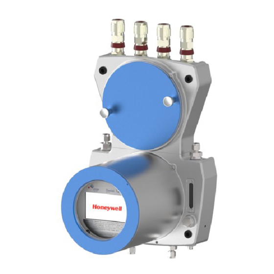
STRUCTURE AND INSCRIPTIONS OF THE GASLAB Q2 3. Structure and inscriptions of the GasLab Q2 GasLab Q2 is a compact device housed in a two-piece explosion-proof aluminum housing. The parts are mechanically and electrically connected. The measuring instrument contains all parts required to fulfil the measuring task. -
Page 44: Connection Section
STRUCTURE AND INSCRIPTIONS OF THE GASLAB Q2 3.1. Connection section The connection section is sub-divided into the following parts • Gas connections (inputs/outputs and breather) • Electrical connections (cable inlet and connection circuit board) 3.2: Overview of connection section/connection points... - Page 45 STRUCTURE AND INSCRIPTIONS OF THE GASLAB Q2 Gas connections (inlets / outlets and breathing elements) The gas connections are pipe fittings and are equipped by the manufacturer. The gas inlets are located at the bottom of the device. Left for process gas with integrated particle filter.
-
Page 46: Instrumentation Section
If the ball is within the marks, there is enough flow for operation. A gas flow already exists even with stationary balls. Honeywell recommends the use of an additional flow meter in the gas path in cases where the exact flow rate is critical. -
Page 47: Human-Machine Interface (Hmi)
LEDs that indicate the status of the device. During normal operation the GasLab Q2 can be operated completely via the operation panel, which is equipped with 7 touch fields, as it allows direct reading of the measured and target values as well as control and settings. -
Page 48: Type Labels And Setting Marks
STRUCTURE AND INSCRIPTIONS OF THE GASLAB Q2 3.4. Type labels and setting marks The main type label with the most important information is located below the interactive screen, behind the inspection window. If the type label is covered by the sand guard, this information can also be read off an additional type label on the outside of the housing. - Page 49 STRUCTURE AND INSCRIPTIONS OF THE GASLAB Q2 In addition, the type labeles contain information about the approvals granted and the explosion protection properties. Not all certificates and approvals are listed in this documentation. The following table shows a selection. Approvals (selection) Only the specifications on the respective device apply! (For EU) Approval number DEKRA 15.ATEX0113X /IECEx DEK 15.0075X...
-
Page 50: Explanation Of Explosion Protection Markings
STRUCTURE AND INSCRIPTIONS OF THE GASLAB Q2 Apart from the type labeles, there is still engraved information on the device. Next to the flow meters there are setting marks for the gas flow rates. Arrows at the inlet and outlet indicate the direction of the gas flow. Above the gas inlets, the maximum inlet pressures are also indicated, which must not be exceeded under any circumstances. - Page 51 STRUCTURE AND INSCRIPTIONS OF THE GASLAB Q2 Used Description / Explanation Shorthand II2G Ex marking complete device suitable for ex- zone 1 and 2 (gases/vapours) Ex-zones Potentially explosive areas are divided into zones according to the frequency and duration of occurrence of hazardous explosive atmospheres. The following applies to...
-
Page 52: Measurement Technology And Measuring Point
Instead of the gas values such as superior calorific value, density at base conditions and CO content, the measuring method uses values which are physically related to the target values and are easier to measure. GasLab Q2 therefore analyzes the following gas properties: •... - Page 53 . The flow rate may be changed /h to 2.118 ft /h ≙ 0.03 m /h to 0.06 m /h ≙ 30 l/h to 60 l/h depending on the application. Information for general use GasLab Q2 Rev. M / 73023639...
-
Page 54: Measuring Point Overview
The stream of gas is measured quickly and continuously and then fed into the vent (waste) gas. If the pipeline pressure is higher than the maximum inlet pressure of the GasLab Q2, a pressure reduction system must be installed and adjusted upstream of the process gas inlet. -
Page 55: Gaslab Q2 After Delivery And At The Place Of Use
Mechanical installation of GasLab Q2 Connect the gas pipelines and the auxiliary and vent lines to the GasLab Q2 and set the gas pressures, open the shut-off valves and check all lines for leaks. Fluid installation of GasLab Q2 ... -
Page 56: Storage
If the device is transported in cold weather or extreme temperature fluctuations have occurred, GasLab Q2 must be slowly returned to room temperature (temperature at the place of use) in order to prevent damage caused by the formation of condensation. -
Page 57: Mechanical Installation Of Gaslab Q2
à risque d’explosion. The GasLab Q2 must be installed as close as possible to the process gas sampling point to avoid having long supply lines and to ensure that you obtain current measurements. -
Page 58: Device Dimensions
GASLAB Q2 AFTER DELIVERY AND AT THE PLACE OF USE 5.2.2. Device dimensions Please note that dimensions following drawing shown The dimensions with information (1 (2 (3 depend on the types of fluid and electrical couplings used. Figure 5.1: Dimension drawing (with optional sand guard) -
Page 59: Fluid Installation Of Gaslab Q2
Fittings and pipe couplings with few dead spaces are to be preferred. Route the gas pipelines to the GasLab Q2. Ensure that every pipeline and every gas route is fitted with the required safety, shut-off and pressure regulation equipment. Shut-off valves and pressure regulators are not parts of the measuring device and are not included in the scope of delivery. -
Page 60: Fluid Interfaces
GASLAB Q2 AFTER DELIVERY AND AT THE PLACE OF USE 5.3.1. Fluid interfaces GasLab Q2 has 2 gas inlets and two gas outlets, each of which is protected by a flame arrester. Two breathing points are used to enable atmospheric pressure equalisation between the inside of the device and the environment. -
Page 61: Connect The Vent Gas Line
5.3.2. Connect the vent gas line Vent gas lines must be vented atmospherically and protected from dirt and moisture. These lines must be routed to a safe area away from GasLab Q2, as flammable gas flows through them permanently. Les conduites de gaz d’échappement de l’appareil doivent assurer une ventilation atmosphérique et être protégées contre la saleté... -
Page 62: Connect The Process Gas Line
0.15 MPag ≙ 21.76psig ≙ 1.5barg and maximum 0.3MPag ≙ 43.51psig ≙ 3barg. (The exact pressure will be set later). The pipeline is now ready for connection to GasLab Q2. Prevent the penetration of dirt and moisture if the connection is not made immediately. -
Page 63: Connect The Calibration Gas
GASLAB Q2 AFTER DELIVERY AND AT THE PLACE OF USE 5.3.4. Connect the calibration gas For proper operation of the GasLab Q2 a regular automatic calibration with a binary mixture of methane (CH ) and carbon dioxide (CO ) is necessary. Normally the mixture is taken from a gas cylinder close to the instrument. -
Page 64: Electrical Installation
Always observe the general safety rules, especially in potentially explosive atmospheres. Always use a gas detector when working on the instrument and make sure that the GasLab Q2 is voltage-free (supply and signals) before any change of the wiring. The local / national installation guidelines (e.g. -
Page 65: Power Supply And Protection
énergie doit garantir la protection contre la surtension/surintensité et la protection de la ligne électrique. GasLab Q2 does not have any protective devices which can be replaced by the user. The internal thermal and electrical fuses cannot be reset. -
Page 66: Cables (Power Supply / Communication)
GASLAB Q2 AFTER DELIVERY AND AT THE PLACE OF USE 5.4.2. Cables (power supply / communication) For the connection between GasLab Q2 and other instruments different control and signal cables are suitable, the choice depends on the requirements at the place of use. -
Page 67: Opening And Closing The Connection Box
GASLAB Q2 AFTER DELIVERY AND AT THE PLACE OF USE 5.4.3. Opening and closing the connection box To carry out the electrical installation and for subsequent maintenance work, the connection box must be opened. Never open the device at the place of use without the permission and consent of the system operator. -
Page 68: Grounding And Potential Equalisationerdung Und Potentialausgleich
3.5Nm ≙ 2.582 ftlb. If GasLab Q2 is mounted on a metal plate, the plate must be properly included in the grounding and the equipotential bonding system. Use the appropriate connections or install such connections. -
Page 69: Cable Glands (Adapter / Dummy Plugs)
GASLAB Q2 AFTER DELIVERY AND AT THE PLACE OF USE 5.4.5. Cable glands (adapter / dummy plugs) On the upper side of the device there are four threaded holes with M20x1.5 thread. These can be fitted as required. Possible are dummy plugs, adapters (½"NPT thread) or cable glands like shown... - Page 70 GASLAB Q2 AFTER DELIVERY AND AT THE PLACE OF USE The required accessories listed below are supplied in the recommended or ordered version. List of cable glands and dummy plugs recommended by Honeywell (all threads M20x1,5): Type of dummy plug...
-
Page 71: Electrical Connection Diagram And Electrical Interfaces (Inputs And Outputs)
Dans la pratique, les blindages ne sont pas installés à l’intérieur de la zone explosible, mais seulement à l’extérieur. The possible electrical connections for the GasLab Q2 are shown in the following diagram: Information for general use GasLab Q2 Rev. - Page 72 GASLAB Q2 AFTER DELIVERY AND AT THE PLACE OF USE Figure 5.6: Electrical connection assignment (circuit board) Information for general use GasLab Q2 Rev. M / 73023639...
-
Page 73: Connection To Other Devices And System Parts
GASLAB Q2 AFTER DELIVERY AND AT THE PLACE OF USE 5.4.7. Connection to other devices and system parts The connection diagrams for sensors and devices to which the GasLab Q2 can be connected are shown in example form in the following. This may require special parameterization in enSuite. - Page 74 GASLAB Q2 AFTER DELIVERY AND AT THE PLACE OF USE Ethernet Cable type refer to 5.4.2 Cables (power supply / communication) length 100m ≙ 328ft. The connection is made using the terminals designated TB3-1 to TB3-4 in the Q2 connection box.
- Page 75 GASLAB Q2 AFTER DELIVERY AND AT THE PLACE OF USE Serial interface RS485 Connections include, for example, other measurement devices, devices for final processing and evaluation, PLC systems, and so on. Cable type refer to 5.4.2.Cables (power supply / communication).
- Page 76 GASLAB Q2 AFTER DELIVERY AND AT THE PLACE OF USE Digital inputs There are two electrically isolated inputs supplied in the connection box (TB5-terminals 1 to 2 and TB5-terminals 3 to 4, details see figure 5.6). The maximum supply voltage is approx. 9 V.
- Page 77 GASLAB Q2 AFTER DELIVERY AND AT THE PLACE OF USE Digital outputs There are four digital outputs (electrically isolated passive output circuits) in the connection box (TB6-terminals, details see figure 5.6). The output at TB6-5 is a breaker (NC, “normally closed”), the other outputs are makers (NO, “normally open”).
- Page 78 GASLAB Q2 AFTER DELIVERY AND AT THE PLACE OF USE Analog outputs There are four common electrically isolated active output circuits (“common ground”/short-circuit- resistant) with 0 or 4 to 20 mA in the connection box (TB7-terminals, details see figure 5.6). The maximum supply voltage is around 9 V.
-
Page 79: Commissioning And Decommissioning
Before commissioning, make sure that Chapter 2 Safety and warning information have been observed and followed and that the GasLab Q2 has been installed and connected in accordance with this document. All new devices are supplied with default parameter set also called parameterization, which enables them to perform the measuring task. -
Page 80: Set Password For Administrator (Admin1)
Respectez les règles de protection contre les explosions et de sécurité ! Additionally, the housing hood may only be removed in controlled conditions as described in ISO/IEC 61010-1. Information for general use GasLab Q2 Rev. M / 73023639... - Page 81 31°C, falling in linear form to 50% at 40°C ≙ 104°F ≙ 313K ) generally prevail in residential and office environments. Contact Honeywell if you are in any doubt. The instrumentation section contains sensitive parts which can easily be damaged by mechanical or electrostatic effects.
-
Page 82: Additional Conditions For Fiscal Metering
A small mirror will also help you to find the connection pins and check that it is correctly positioned. You can view the setting by using devices displays and enSuite. See chapter 7 GasLab Q2 Displays (Operate the Device) and chapter 8 Configuration and analysis software enSuite 6.1.4. Additional conditions for fiscal metering In the case of fiscal use, the conditions laid down in the relevant approval must be met. -
Page 83: Standard Commissioning And Normal Operation
Check and change the device settings and signals if necessary, see next section GasLab Q2 works continuously after all steps have been carried out and the standard commissioning is finished. The right LED flashes in RED when errors occur. -
Page 84: Checking The Setting And Signals
être complètement fermée! A complete check of the current parameter set can be made using the enSuite configuration and analysis software with an online connection to the GasLab Q2. See also section 8.4.3 Changing the device parameter set in the connected device (online parameterization). -
Page 85: Decommissioning / Dismantling / Disposal
Data for example, archive data and time settings, will be lost if the battery is empty. The device will no longer start correctly. You will then require a Honeywell service visit. La batterie tamponne les données pendant environ un an et peut avoir besoin d'être remplacée par la suite. - Page 86 COMMISSIONING AND DECOMMISSIONING Disposal: GasLab Q2, like all enCore devices, falls under the WEEE directive. The adjacent EU WEEE symbol symbolises that this device may not be disposed of with household waste in the EU. As the EU member states have transposed the WEEE directive into national legislation in different ways, the regulations for the return of disused equipment vary.
-
Page 87: Gaslab Q2 Displays (Operate The Device)
GASLAB Q2 DISPLAYS (OPERATE THE DEVICE) 7. GasLab Q2 Displays (Operate the Device) GasLab Q2 will begin its starting procedure after the power supply has been connected and it has been switched on. After this starting procedure has been completed, the device will provide an overview of the state of the measurement on the screen. -
Page 88: Leds Above The Interactive Screen
GASLAB Q2 DISPLAYS (OPERATE THE DEVICE) 7.1. LEDs above the interactive screen There are two multi-colored LEDs positioned above the interactive screen. The Power LED on the left and the Status LED on the right. They are simulated on the remote operation panel. -
Page 89: The (Local / Remote) Operation Panel
GASLAB Q2 DISPLAYS (OPERATE THE DEVICE) 7.2. The (local / remote) Operation panel The screen or display on the device is interactive (part of the HMI, see section Human-machine interface (HMI)) and is also called operation panel. The display lighting is switched off automatically after a period of inactivity, whose length is adjustable. -
Page 90: Navigation In The Operation Panels And Displays
GASLAB Q2 DISPLAYS (OPERATE THE DEVICE) 7.2.1. Navigation in the operation panels and displays The following section describes the menu control and local and remote operation in general form on the basis of examples. Following figure provides an initial overview of the structure of the display. - Page 91 GASLAB Q2 DISPLAYS (OPERATE THE DEVICE) Refer to the following information relating to the superimposition keys • The first time the (invisible) sensitive areas are activated, the superimposition keys will only be displayed without any further functions being executed. They will then disappear again after 30 seconds if no further action is taken.
- Page 92 GASLAB Q2 DISPLAYS (OPERATE THE DEVICE) Hyperlinks and actions are shown in the displays in blue. Figure 7.5: Hyperlinks and actions Hyperlinks enable you to navigate through the displays by opening the appropriate display automatically when they are activated. Actions enable you to perform a specific function.
- Page 93 GASLAB Q2 DISPLAYS (OPERATE THE DEVICE) Selectable points are underlined in blue, for example, “Device monitor” and “Software status” in Figure 7.5. If the text is not underlined, as is the case with “Reset battery status to 100%” (in the next...
- Page 94 (symbols with a maximum of 2 taps. This display is the GasLab Q2 main display. It is also automatically displayed after lengthy breaks in operation. Information for general use GasLab Q2 Rev.
-
Page 95: The Middle Of The Bottom Status Line And The Visibility Of The Displays
GASLAB Q2 DISPLAYS (OPERATE THE DEVICE) 7.2.2. The middle of the bottom status line and the visibility of the displays Additional information symbols are shown at times in the center of the bottom line: Figure 7.9: Symbols in the middle of the status line of displays These symbols are only displayed in context. - Page 96 GASLAB Q2 DISPLAYS (OPERATE THE DEVICE) The following table gives an overview: means that the security switch (SSW) is open. means that the user is logged in. One or more remote controls are active. The local user sees the screen content and can operate the device The device is operated remotely.
-
Page 97: Entries And Changes Using The Operation Panel
GASLAB Q2 DISPLAYS (OPERATE THE DEVICE) 7.2.3. Entries and changes using the operation panel Changes on the device are always made in the following steps: • Log into the device • Complete and confirm the changes on the device •... - Page 98 GASLAB Q2 DISPLAYS (OPERATE THE DEVICE) Changes using a displayed keypad for entering letters and numbers. To prevent local users from inadvertently blocking remote access, the virtual keyboard closes automatically after one minute of inactivity - no input is visible on the remote operation panel.
-
Page 99: Displays And Functions
After start-up or power-up, the “Home” display can be accessed using This is a special display; it shows the software structure of the GasLab Q2. Individual software parts and selected other functions which should be easy to access (for example, changing the language) are displayed here in the form of small symbols. - Page 100 GASLAB Q2 DISPLAYS (OPERATE THE DEVICE) Navigation options in the Home display Selecting a symbol (using the superimposition keys) in the Home display will open it to display the functions grouped in this folder. If only one function is assigned to this symbol, selecting it will immediately take you to the main display of this function.
- Page 101 Up to two languages are possible. English is always the second language. The devices will always start in the first language. Please notify Honeywell if you wish to change the first language installed in the device. If English is selected as the first language, the device can only be operated in English.
-
Page 102: Info Display (Overview)
GASLAB Q2 DISPLAYS (OPERATE THE DEVICE) 7.3.2. Info display (overview) This symbol opens the following display: The display shows the device’s serial number (first line) and the status of the security switch (SSW). This is a switch which can be sealed, also known as the calibration switch. - Page 103 GASLAB Q2 DISPLAYS (OPERATE THE DEVICE) The certificate display shows the details of the used certificate for secure data transmission. Since the display is too long to be shown completely, use the small yellow diamond on the right-hand edge or scroll use the up and down arrows on the display.
-
Page 104: Info Display (Device Monitor)
The device will no longer start correctly. DANGER OF EXPLOSION IF THE BATTERY IS NOT REPLACED CORRECTLY. The battery replacement must be carried out by Honeywell service personnel. Information for general use GasLab Q2... -
Page 105: Info Display (Software Status)
à la perte de données de mesure calculées et stockées. L’appareil ne démarre plus correctement. RISQUE D’EXPLOSION EN CAS DE REMPLACEMENT NON CONFORME DE LA BATTERIE. Le remplacement de la batterie doit être effectué par le personnel de service de Honeywell. Info display (Software Status) 7.3.5. - Page 106 GASLAB Q2 DISPLAYS (OPERATE THE DEVICE) Figure 7.21: System info – Software info display The above figure only shows examples. If, for example, the device is not used without an approval file, the “Secured parameters” display will not be available. Furthermore, some links can only be selected if there are no red entries.
-
Page 107: Info Display (Display Test)
GASLAB Q2 DISPLAYS (OPERATE THE DEVICE) Info display (Display test) 7.3.6. Display test shows a display in which all the pixels in the display area are switched on and off alternately. This enables you to check whether the screen is working correctly. -
Page 108: Error List - Main Display (Accepting / Quit Error Messages)
GASLAB Q2 DISPLAYS (OPERATE THE DEVICE) 7.3.8. Error List – Main display (accepting / quit error messages) Background: If the status LED is lit or flashing in red or yellow, there are entries in the error list. The device manages warning and alarm messages in this list and records them in the logbook. - Page 109 GASLAB Q2 DISPLAYS (OPERATE THE DEVICE) Item Error List details Filter selection box: In the first line, you can use the drop-down list to restrict the display to the selected range. Action Accept all: All displayed errors which are no longer current can be accepted at the same time so that they are no longer displayed.
- Page 110 GASLAB Q2 DISPLAYS (OPERATE THE DEVICE) Entries in the error list must be accepted (see the following steps). On delivery of the device, this is only possible using the defined acceptance action if the cause of the entry has been rectified.
-
Page 111: System Display (Overview)
GASLAB Q2 DISPLAYS (OPERATE THE DEVICE) System display (overview) 7.3.9. The system display, a node to additional displays, is opened by selecting this symbol. You can go to the following sub-displays using this node: Time Service, Users, Logbook, Audit trail, I/O. - Page 112 GASLAB Q2 DISPLAYS (OPERATE THE DEVICE) Figure 7.26: Time Service display overview Depending on the user's authentication, the main display branches to the corresponding display to change the system time. The hyperlink NTP overview is only displayed when time polling via NTP is enabled in the enCore device.
- Page 113 GASLAB Q2 DISPLAYS (OPERATE THE DEVICE) The Time Service main display shows the date and time (also known as the system time). The abbreviation (DST) means daylight saving time and is only shown if the current time is in daylight saving time.
- Page 114 GASLAB Q2 DISPLAYS (OPERATE THE DEVICE) Step Action: Time synchronization (can be performed by all users) Open the Time Synchronization display without logging in (System > Time Service > Date & Time). Enter the seconds (box after Time synchronization by) by which the system time is to be changed.
- Page 115 GASLAB Q2 DISPLAYS (OPERATE THE DEVICE) Step Action: Setting the time and date If applicable, click on the Daylight saving box. This is only possible if the appropriate setting has been made in enSuite. Then choose between the following: Active The device’s system time is in daylight saving time.
-
Page 116: System Display Users (Login/Logout / Password)
This warning (see above picture on the right) is displayed whenever a user uses the remote operation panel. This warning is shown on the GasLab Q2 if there is a connection to enSuite and the remote operation panel is not used or the lock screene has been removed via enSuite user. - Page 117 GASLAB Q2 DISPLAYS (OPERATE THE DEVICE) If no user is logged on to the device, the User name box shows the name of the last user. “Login” is possible if your user name appears on the list and you select it. See the following example figure.
- Page 118 GASLAB Q2 DISPLAYS (OPERATE THE DEVICE) If no action is carried out, you will be logged out automatically after a preset/adjustable time. (Further information about this inactivity timeout can be found in section 8.2.2 Starting enSuite; the first steps). After logging in, you can make changes to the parameters. You can then save or discard them. You can also change your own password or create a new one.
- Page 119 Red text indicates that the password has not been saved. Figure 7.33: Users main display for changing the password With the appropriate parameterization, you can additional / alternative protect GasLab Q2 against unauthorized access by operating whis closed SSW. Step “Logout”...
-
Page 120: System Display (Logbook)
GASLAB Q2 DISPLAYS (OPERATE THE DEVICE) 7.3.12. System display (Logbook) The device has 2 logbooks: the “Logbook” and the “Audit trail” in which events are saved as a history during operation. The logbook (Logbook error list, see the figure below) documents / saves events and protocol the device operation in this way. - Page 121 GASLAB Q2 DISPLAYS (OPERATE THE DEVICE) See also the following table: Identification Meaning Event begins Event ends <Black text> Event of type Information <Yellow text> Event of type Warning <Red text> Event of type Alarm Whenever changes occur or an event is included in or removed from the Error List main display, this information is recorded in the logbook.
-
Page 122: System Display (Audit Trail)
GASLAB Q2 DISPLAYS (OPERATE THE DEVICE) 7.3.13. System display (Audit trail) The audit trail is another protocol archive for documentation. It is part of the basic system and therefore available in all enCore device types. The contents are displayed in the current device language. - Page 123 GASLAB Q2 DISPLAYS (OPERATE THE DEVICE) The type and scope of the displayed data depends on the situation and the settings in enSuite. For further information see enSuite online help. All the data in the audit trail is also saved in the logbook, which means that the entire recorded history is visible in it.
-
Page 124: System Display I/O (Basic Network Settings / Inputs /Outputs)
GASLAB Q2 DISPLAYS (OPERATE THE DEVICE) 7.3.14. System display I/O (basic network settings / Inputs /Outputs) The I/O – Overview display lists all the device parts available on inputs or outputs and enables the user to go to other sub-displays using hyperlinks. - Page 125 GASLAB Q2 DISPLAYS (OPERATE THE DEVICE) If a user is logged in with the appropriate rights, the basic network settings can be changed in the Ethernet I/F (Ethernet interface) display, see the figure below. Figure 7.40: I/O displays with options to make an entry and restart The setting of the IP address and the basic network settings is not only via the operationn panel but also via enSuite.
-
Page 126: Display Q2 Sensor Values
GASLAB Q2 DISPLAYS (OPERATE THE DEVICE) 7.3.15. Display Q2 sensor values The list of sensor values can be opened by clicking on this symbol. Generally, this display is only used for service purposes and for locating errors. Figure 7.41: Q2 sensor values display... -
Page 127: Display Q2 Control (Calibration/Verification/Touch)
see section Operating mode: Verification (special mode) Displays and functions for “Base calibration” not described (The base calibration is only carried out by Honeywell at the factory before delivery) Information for general use GasLab Q2 Rev. M / 73023639... - Page 128 GASLAB Q2 DISPLAYS (OPERATE THE DEVICE) The Calibration data display lists internal instrument values and deviations from previous settings caused by the operating calibration Figure 7.43: Q2 – Calibration data (Sub-display of Calibartion display) The display of the calibration values is not required in everyday operation. It is for service purposes only and may help troubleshooting work.
-
Page 129: Q2 Main Display (Calculation Standard)
GASLAB Q2 DISPLAYS (OPERATE THE DEVICE) 7.3.17. Q2 main display (calculation standard) This symbol takes you to the Q2 main display (display when the devices started set at the factory). Alternatively, you can use the button (home display bottom right). - Page 130 The states shown in the following can also be recorded outside normal operation using the Modbus numbers. These only occur during the base calibration at the factory, during Honeywell service work or in the event of errors and are therefore not described in further detail here.
- Page 131 GASLAB Q2 DISPLAYS (OPERATE THE DEVICE) Operation Step Meaning Idle (0) Idle (20) Device in idle state Confirm 2 (2) Wait for confirmations by user Gas 2 (3) Recording measurements, calibration gas 2 Confirm 3 (4) Wait for confirmations by user...
- Page 132 GASLAB Q2 DISPLAYS (OPERATE THE DEVICE) For information about changing or extending this setting, see section 8.4 Changing existing device settings (Parameterization) These control and information lines are followed by the measurement and calculation values (results). The values displayed are only valid if the system is in analysis mode and has not suffered an error.
- Page 133 GASLAB Q2 DISPLAYS (OPERATE THE DEVICE) The first element that can be selected in the control and information lines is the “Details” button. It allows intermediate results to be viewed in another display. Once again, the selection and activation is done using the superimposition keys.
- Page 134 GASLAB Q2 DISPLAYS (OPERATE THE DEVICE) The following values can be found in the sub-display Details of the main display: Displayed value Meaning (of the value abbreviation)/Physical quantity (abbreviation) Superior calorific value; molar Superior calorific value; based on volume Superior calorific value; based on mass Inferior calorific value;...
-
Page 135: Display User Archives
User archives This symbol takes you to the main display of the User Archives AFB, which can be used by multiple devices, in other words, also by the GasLab Q2. The following figures and explanations are only examples, further information and the actual set-up... -
Page 136: Display Modbus
This symbol takes you to the main display of the Modbus AFB which can be used by multiple devices, in other words, also by the GasLab Q2. The following figures and explanations are only examples, further information and the actual set-... -
Page 137: Operation And Operating Modes Of Gaslab Q2
The two LEDs will be permanently lit. Apart from intervention by the operator, the analysis will only normally be interrupted by the automatic operational calibration. GasLab Q2 must perform an operational calibration at least once per week. This normally runs fully automatically see section 8.4.9 Setting or changing automatic measurements... - Page 138 GASLAB Q2 DISPLAYS (OPERATE THE DEVICE) Step Action: Manual operational calibration Click on “Gas components” in the “Operational calibration” line. Check or correct the calibration gas mixture using the manufacturer’s analysis certificate. Entries and amendments ( see 7.2.3 Entries and changes using the operation panel).
-
Page 139: Operating Mode: Verification (Special Mode)
The parameters from the last successful calibration remain in use until a new successful calibration has taken place. Errors will be displayed on the device and documented in the “Error List”. If necessary, contact Honeywell to arrange the appropriate action, for example a base calibration. 7.4.3. Operating mode: Verification (special mode) This operating mode can be used for device control. - Page 140 GASLAB Q2 DISPLAYS (OPERATE THE DEVICE) The comparison can be carried out on the actual displays. Use the superimposition keys to navigate to the Verification display and select “Deltas” in the topmost line. The differences between the measurement results and the data saved on the manufacturer’s analysis certificate are visible in this display (only if a measurement has been completed, otherwise “?”...
- Page 141 GASLAB Q2 DISPLAYS (OPERATE THE DEVICE) Step Action: Manual verification On the display shown to the side, activate “Start” using the superimposition keys (after re- activating “Verification” if step 2 has been completed) Figure 7.59: Q2 – Verification display The analysis (current measurement) will no longer be updated or will be stopped.
- Page 142 GASLAB Q2 DISPLAYS (OPERATE THE DEVICE) Step Action: Manual verification The measurement will now run for the time previously set in enSuite (see section 8). You can end the verification prematurely by selecting “Stop”. You will then jump to step 9.
-
Page 143: Configuration And Analysis Software Ensuite
CONFIGURATION AND ANALYSIS SOFTWARE ENSUITE 8. Configuration and analysis software enSuite In addition to on-site operation on the GasLab Q2 instrument screen, you have the option of accessing the instrument using a computer via the enSuite configuration and analysis software. -
Page 144: The Pc-Software-Concept
Further details of the software can be found directly in the enSuite online help. Please also observe the other notes in this chapter before working with the GasLab Q2 via PC. Always use the current enSuite version for your work from the download area (see next pages). -
Page 145: Installation Start And Data Connection
No restart is required after completing the installation and the shortcut symbol shown here will appear on your desktop. For non-fiscal operation, the enSuite configuration and analysis software also allows communication via a network interface using the Modbus TCP protocol. Information for general use GasLab Q2 Rev. M / 73023639... -
Page 146: Starting Ensuite; The First Steps
X also removes the detachment. EnSuite remembers the position of the windows from previous applications. The “Reset windows” function (see menu bar under the window) enables you to restore the default state. Information for general use GasLab Q2 Rev. M / 73023639... - Page 147 You can activate the general online help via the menu item Help – Show online help. Open the context-sensitive help directly from the desired branch in the parameterization window with [F1]. Information for general use GasLab Q2 Rev. M / 73023639...
- Page 148 It includes information for setting the inactivity timeout and the automatic logout. The sub-sections below provide more details of this information and are easier to understand with this background knowledge. Information for general use GasLab Q2 Rev. M / 73023639...
-
Page 149: General Connection Options To The Encore Device
Connecting the enCore device via TCP/IP The Device is mounted in an accessible computer network. Cable type according to Category 5 (cat 5) Connect the service PC and enCore device with a cable. Information for general use GasLab Q2 Rev. M / 73023639... -
Page 150: Establish A Connection To The Encore Device
In both cases, a dialog to select the connection path then appears once the option is activated Figure 8.5: D ialogs Search device and connect and Connect (examples) Information for general use GasLab Q2 Rev. M / 73023639... - Page 151 1. select the corresponding function e.g. in the navigation window or on the button bar 2. enter the connection data in the dialog, (see next figure) and confirm with [OK] Figure 8.6: Find and Connect Device (enSuite Window) Information for general use GasLab Q2 Rev. M / 73023639...
- Page 152 This is always the case when the device is connected for the first time. Figure 8.8: Certificate is unknown – example first connection establishment Information for general use GasLab Q2 Rev. M / 73023639...
- Page 153 (Without a connection, you won't be able to compare the fingerprint, so...) ...first check the information on the device in the section Subject of the dialog If the information is correct, establish a temporary connection to the device, as described below Information for general use GasLab Q2 Rev. M / 73023639...
- Page 154 With respect to devices for which a connection has currently been requested but has not yet been established, the device symbol is marked under the Devices branch with a yellow dot Information for general use GasLab Q2 Rev. M / 73023639...
- Page 155 All the steps to make device connection are explained in detail in the “enSuite online help”. Follow these instructions. Information for general use GasLab Q2 Rev. M / 73023639...
-
Page 156: Disconnecting The Device And Connection Errors
See section 8.4 Changing existing device settings (Parameterization) for more details The disconnection of all devices is always done if enSuite is closed! Information for general use GasLab Q2 Rev. M / 73023639... -
Page 157: Read-Out Parameterization
Q2 it is not nessesary to mark the checkbox. You can confirm with [OK]. If the checkbox is selected a login dialog will appear after pressing [OK] button. See section 8.3 User management and login for more details about login. Information for general use GasLab Q2 Rev. M / 73023639... -
Page 158: Saving, And Exporting The Parameter Set
After double-clicking on the file, enSuite will open the parameterization window and show the parameter set. See the online help for more information about this window. Information for general use GasLab Q2 Rev. M / 73023639... -
Page 159: Viewing The Parameterization Of Sfbs And Afbs
If some of the elements shown in Figure 8.16 are colored orange, there is a conflict with the approval file, see section Fiscal parameters and optional using approval file (Select approval) 8.4.10 Information for general use GasLab Q2 Rev. M / 73023639... - Page 160 The Modbus AFB allows communication, for example, if TCP/IP has not been configured for the data transfer or data exchange. It has its own operating manual, which you can download from the Docuthek (www.docuthek.com). The online help contains all the other information you require. Information for general use GasLab Q2 Rev. M / 73023639...
- Page 161 Attention: It is possible that the parameterization is no longer valid when an AFB has been deleted. In such cases all parameter branches and parameters which contain references to the deleted AFB that are no longer valid are labeled in red. Information for general use GasLab Q2 Rev. M / 73023639...
-
Page 162: User Management And Login
User management and login Like all enCore devices, the GasLab Q2 has a user management system. In principle, a parameter can only be changed and used in the device if the user is entitled to do this and the position of the security switch (SSW) allows it. -
Page 163: User Profile Management
Si vous êtes connecté en tant qu’administrateur, vous disposez de l’ensemble des droits sur l’appareil. Tous les préréglages effectués en usine peuvent être modifiés, même accidentellement. Effectuez vos travaux en prenant les précautions adéquates! Information for general use GasLab Q2 Rev. M / 73023639... -
Page 164: Assigning Or Changing A Password Using Online Parameterization
CONFIGURATION AND ANALYSIS SOFTWARE ENSUITE 8.3.2. Assigning or changing a password using online parameterization Connect to the GasLab Q2 and select “Parameterize online” (see section 8.4.3 Changing the device parameter set in the connected device (online parameterization) for further information). A login prompt will appear in which you must log in as the administrator or super user (for example, SU3). -
Page 165: Viewing Setting And Change Access Rights
Changes not made by the administrator are rejected by the device after transmission. The lines only serve as information display to all other users. The administrator can define further user rights on the following page: Information for general use GasLab Q2 Rev. M / 73023639... -
Page 166: Viewing Position Of The Security Switch
Figure 8.20: View the SSW position (open and closed) On delivery and in “non-fiscal operation”, this connection is open. When the switch is closed, the text "The security switch is currently closed" is displayed. Information for general use GasLab Q2 Rev. M / 73023639... -
Page 167: Access Rights Dependent Restricted Editing Options (Virtual Login)
Non-editable parameters are listed in gray in the parameter lists and are labeled with the symbol By using the option Show enabled parameters only, you can achieve that any such parameters are not displayed at all. Information for general use GasLab Q2 Rev. M / 73023639... - Page 168 You will now see the existing setting options under Parameters. Figure 8.23: Parameters with out virtual login If you were to make changes as user SU3, the device would reject the parameter set after the transfer. Information for general use GasLab Q2 Rev. M / 73023639...
-
Page 169: Changing Existing Device Settings (Parameterization)
(e.g. by activating functionalities or adding process boards). Restarting the device after installing the No restarting the device. parameterization. Information for general use GasLab Q2 Rev. M / 73023639... - Page 170 This applies to all changes, even if they are not specifically mentioned below: Select the parameter to be changed from the parameter tree. Activate the input field and press [F1] to obtain information and change aids. More information in the following section. Information for general use GasLab Q2 Rev. M / 73023639...
-
Page 171: Changing Device Parameters Offline (Offline Parameterization)
All the parameters for editing are subject to the user management restrictions and can only be changed or transferred to the device with the appropriate rights and with the SSW in the appropriate position. Information for general use GasLab Q2 Rev. M / 73023639... - Page 172 See the following examples: Figure 8.24: Example of left- and right-hand sections of the parameterization window Figure 8.25: Example of reactions in the param. window after using a drop-down box Information for general use GasLab Q2 Rev. M / 73023639...
- Page 173 Figure 8.27: Example of export values in the Export values window Whether the parameter type can be switched, depends on the actual parameter. More details of the parameter types, units and windows are given in the online help. Information for general use GasLab Q2 Rev. M / 73023639...
- Page 174 Instead of changing a read-out parameterization, you can also adapt a new parameterization from the templates, as described in the next section. Then transfer the parameterization to the device. The procedure and further parameterization tips are also described in the next section. Information for general use GasLab Q2 Rev. M / 73023639...
-
Page 175: Create A New Device Parameter Set (Offline Parameterization)
The tabular listing of parameters in the parameter window has several columns. The name of the parameter (Parameter name column) depends on the selected language. You can see the current value of the parameter in the Value column; here, changes can be made. Information for general use GasLab Q2 Rev. M / 73023639... - Page 176 This symbol shows at a glance to which physical quantity the value belongs. Examples: Symbol Physical quantity temperature pressure (absolute or gauge) volume (volume at base conditions, volume at measurement conditions) energy heating value Information for general use GasLab Q2 Rev. M / 73023639...
- Page 177 This is carried out centrally under Basic System – Unit service – Default units. You can find out more information on the Unit service SFB in the Online Help and in section 8.4.7Changing units and adjusting display formats in the Unit Service SFB Information for general use GasLab Q2 Rev. M / 73023639...
- Page 178 After it has been saved, the symbol will turn gray and the lines will be displayed in black. The saved valid device parameter set can now be transferred to the device with the appropriate serial number. Information for general use GasLab Q2 Rev. M / 73023639...
- Page 179 The device will now operate using the transferred settings after you have re-enabled the required operating mode. These new settings will remain in use even after the device is switched off and on again. Information for general use GasLab Q2 Rev. M / 73023639...
-
Page 180: Changing The Device Parameter Set In The Connected Device (Online Parameterization)
(Once they have been saved, the values will again be displayed in black.) Then click on the topmost folder in the parameter tree, select the tab as shown and check your login status. Log out by closing the online parameterization window. Information for general use GasLab Q2 Rev. M / 73023639... -
Page 181: Product And Device Parameterizations
Two different types of stored parameterizations are provided in the enSuite database: A Product parameterization belongs to an enCore product class (e.g. enCore FC1, GasLab Q2, proChain GC) and may be used as a template when creating a parameterization for a specific device. -
Page 182: Changing The Ip Address Basic Network And I/O Settings
Change or activate the following I/O interfaces (the parameters open after clicking the folder) for communication and data exchange with other devices. Information for general use GasLab Q2 Rev. M / 73023639... - Page 183 Ethernet settings For data communication, connections via Ethernet are mainly used. Go to parameter branch: GasLab Q2 – Basic system – I/O – Board 0: CPU. Fill in your changes, proceed like explained in the online help. Serial interface RS485 These connections include, for example, other measuring instruments, devices for final processing and evaluation, PLC systems, etc.
-
Page 184: Setting Time-Related Values And Actions In The Time Service Sfb
The time is changed automatically based on the predefined rules for the region • user defined The time is changed automatically based on a user-defined Posix TZ string • Depending on the settings selected, the associated parameters will be displayed. Information for general use GasLab Q2 Rev. M / 73023639... - Page 185 Contract hour 2 (numeric) Every day (at 2nd contract hour) Every Sunday (at 2nd contract hour) Every Monday (at 2nd contract hour) Every month (at 2nd contract hour on 1st) Information for general use GasLab Q2 Rev. M / 73023639...
-
Page 186: Changing Units And Adjusting Display Formats In The Unit Service Sfb
It is therefore possible to use the "normal" unit for individual parameters or export values and therefore avoid the unit being automatically adapted due to a change in default unit. Information for general use GasLab Q2 Rev. M / 73023639... - Page 187 To do this, the gradient and offset for the linear conversion of a value in the pre-defined unit to the value in the user-defined unit must be determined. The formula is as follows: Value in user defined unit= gradient × value in predefined unit+Offset Information for general use GasLab Q2 Rev. M / 73023639...
- Page 188 "normal" pre-defined unit (<Unit>) but not from the default unit (<Unit *>). Since a default unit is always also available as a "normal" unit for a physical quantity, select this entry in this case Information for general use GasLab Q2 Rev. M / 73023639...
- Page 189 The exponent is displayed with at least two digits in the device. Where necessary a leading zero (0) is added. Example: In a standardized exponential representation, the value 0.0000123456789 is 1.23456789x10⁻⁵ and is represented in the device as 1.23456789E-05. Information for general use GasLab Q2 Rev. M / 73023639...
- Page 190 Regardless of the representation selected your changes will be implemented in the Format string column immediately as a format string. If necessary, you can restore the pre-defined display format at a later point using [Restore default]. Information for general use GasLab Q2 Rev. M / 73023639...
-
Page 191: Define Basic Display And Edit Display Behavior
Menu editor – Home tab. If you have the appropriate rights, you can use the context menu and the symbols on the right-hand edge to make various changes to settings. Information for general use GasLab Q2 Rev. M / 73023639... -
Page 192: Setting Or Changing Automatic Measurements
The preset flushing times must also be adapted to the local conditions Information for general use GasLab Q2 Rev. M / 73023639... - Page 193 The annual service calibration usually not automated requires an additional different gas mixture Completing a service calibration 10.2 (setting analogous to the above examples in the parameter Service calibration) Information for general use GasLab Q2 Rev. M / 73023639...
-
Page 194: Fiscal Parameters And Optional Using Approval File (Select Approval)
2. Now click on Make compliant. By doing this, the access rights for legally relevant parameters are set in line with the selected approval. The orange labeling is replaced by a blue one as the changes have not yet been saved. Information for general use GasLab Q2 Rev. M / 73023639... - Page 195 AFB. See the online help for further information. If this protection is disabled, “none” (see figure) will be displayed. after “Approval file”. Information for general use GasLab Q2 Rev. M / 73023639...
-
Page 196: Restoring The Parameter Set To Factory Settings (Importing Data)
This procedure deletes all current settings in the device and should only be used as a last option in an emergency. If in doubt, contact Honeywell. Before doing so, save all data that is still required on an independent system. A backup must also be available. -
Page 197: Changing The Software Configuration (Update / Downgrade)
8.4.12. Changing the software configuration (Update / Downgrade) As with all products, the GasLab Q2 is subject to changes and additions from time to time. In this section the software update from the basic system version 3-08-A to version 3-34-A is described as an example. - Page 198 (SSW), i.e. exchange is only possible with the switch open. Access rights should only exist for the administrator or a user profile with the same rights. When opening the seal switch, also observe the legal regulations of the respective country. Information for general use GasLab Q2 Rev. M / 73023639...
- Page 199 Check carefully using the read parameter set whether the update can be used (see requirements). • Select action Software configuration in the bottom section of the navigation window (see next figure). Information for general use GasLab Q2 Rev. M / 73023639...
- Page 200 The replacement of fiscal and non-fiscal software modules can be separately restricted by way of special access rights. Figure 8.38: Window configure software Information for general use GasLab Q2 Rev. M / 73023639...
- Page 201 (Elster) in the example above. For a replacement of the current approval with a new approval file, it must be taken into consideration, to explicitly select the appropriate file. A click in column Replace by ... will open a dropdown menu. Information for general use GasLab Q2 Rev. M / 73023639...
- Page 202 It may be necessary to convert the original parameterisation. For further information on the conversion please refer to the next section, use the parameterization read out for this purpose at the beginning. Information for general use GasLab Q2 Rev. M / 73023639...
- Page 203 You can attempt to reset the change using “Restore previous state” (in the “Configure software” window). Then re-transfer the old, unchanged parameter set. Information for general use GasLab Q2 Rev. M / 73023639...
-
Page 204: Convert Original Parameterization (Optional))
Select the new version for the basic system in the Version column. enSuite searches for the versions of the AFBs that match the basic system and highlights them in green, similar to the example above (the other modules are adapted automatically). Information for general use GasLab Q2 Rev. M / 73023639... - Page 205 Always check all the lines. • Save the updated parameter set and close the window The device parameterization can now be transferred to the device. Information for general use GasLab Q2 Rev. M / 73023639...
-
Page 206: Special Case: Bugfix Software
Figure 8.42: Allow installation of Bugfix firmware As soon as you confirm the setting with [OK] , software modules with a revision change can be transferred to the enCore device. Information for general use GasLab Q2 Rev. M / 73023639... -
Page 207: Remote Operation Panel Functions Of Ensuite
After deactivating the function by closing the window with the X in the first line (shown in the figure above), by disconnecting the device (see section 8.2.5 Disconnecting the device and Connection Information for general use GasLab Q2 Rev. M / 73023639... -
Page 208: Enabling The Local Device Functions
Action: With a click on the button, the local user gets the possibility to operate the device. Current status: The local user can operate the device. Action: Click to deny the local user access to the device. Information for general use GasLab Q2 Rev. M / 73023639... - Page 209 Figure 8.44: Lock screen on remote operating panel during local keyboard entry Local keyboard entries are never visible on the remote operation panel for data protection reasons. Information for general use GasLab Q2 Rev. M / 73023639...
-
Page 210: Using Ensuite Functions In Device Operation
Log in using the dialog which appears. Once you have logged in successfully, the Update device’s date and time tab will open. Figure 8.45: Update date and time navigation window Information for general use GasLab Q2 Rev. M / 73023639... - Page 211 Inactivity timeout Tip: If the output window is not displayed in enSuite, you can open it using the path Window – Output or the <Ctrl + 4> keyboard shortcut. Information for general use GasLab Q2 Rev. M / 73023639...
-
Page 212: Displaying And Reading Analysis Results
Please note that Modbus mainly transmits numbers. For example, the operating mode and the operating step of the device are indicated as export values, by (Modbus numbers), since the plain text is not output here. See www.docuthek.com. Information for general use GasLab Q2 Rev. M / 73023639... -
Page 213: Working With Archives And Logs
“Logbook”, document / store the corresponding events and thus protocol the device operation. Further individual archives can be created via the parameterization in the AFB User archive. The data can be read out, viewed, saved, backed up and exported using enSuite. Information for general use GasLab Q2 Rev. M / 73023639... - Page 214 été écrasés. Il n’est possible de vider ou de supprimer l’archive que si l’on dispose des droits correspondants et que l’interrupteur d’étalonnage est ouvert. Information for general use GasLab Q2 Rev. M / 73023639...
- Page 215 Using the same process as for parameterization, you can also export selected files using the symbols or the export function in the context menu to make yourself independent of your current enSuite installation. Figure 8.48: EnSuite export functions Information for general use GasLab Q2 Rev. M / 73023639...
-
Page 216: Live Data And Trending Function In Ensuite
8.2.4 Establish a connection to the enCore device). Once you are connected to the GasLab Q2, you can right-click on the “Live data and trending” entry in the bottom section of the navigation window. The parameters are then read from the instrument and a new window opens in the center of the screen (see figure). - Page 217 Use as “Time Service display” to provide information about the time setting and events and data linked to it. This information can be opened if the export values from “Time service” are used. Details are given in the next sections. Information for general use GasLab Q2 Rev. M / 73023639...
- Page 218 You can clear the central section again by clicking on “Remove all” and display other values in graphic form. The number values form the Y-axis, while the recording time is shown as the X-axis. Information for general use GasLab Q2 Rev. M / 73023639...
-
Page 219: Use "Live Data Tab" As Device Monitor
The device will no longer start correctly. CAUTION — DANGER OF EXPLOSION IF BATTERY IS INCORRECTLY REPLACED. The replacement of battery must be carried out by Honeywell service personnel additional a permit from the plant operator is needed. -
Page 220: Use "Live Data Tab" To View Time Service Data
(DST) is the practice of advancing clocks during warmer months Figure 8.54: Time service main data The Time zone (geographical location) and the setting of DST could be viewed in the parameter settings of Basic system. See next figure. Information for general use GasLab Q2 Rev. M / 73023639... - Page 221 Stratum: stratum value of the NTP server used for the last time synchronization (number of computers up to the time reference in the NTP hierarchy). Information for general use GasLab Q2 Rev. M / 73023639...
-
Page 222: Use "Live Data Tab" To View The Software Status
(further information about the approval file is provided in section Fiscal parameters and optional using approval file (Select approval)). 8.4.10 Information for general use GasLab Q2 Rev. M / 73023639... - Page 223 If a checksum discrepancy is identified an error is generated. To check this, add the relevant points listed under Event additional in the live data tab. Information for general use GasLab Q2 Rev. M / 73023639...
-
Page 224: Possible Malfunctions And Troubleshooting
étanches et que le câble de mise a la terre ou le conducteur de protection est installé correctement. Information for general use GasLab Q2 Rev. M / 73023639... - Page 225 POSSIBLE MALFUNCTIONS AND TROUBLESHOOTING If the following methods do not produce the required success, contact Honeywell. Contact data details are provided at the start of this document. Rectification of the errors under points 1 – 4 (gas supply error) The following action can be taken if an error occurs in the gas supply, for example abnormal loss of calibration gas.
- Page 226 To do so, switch off the electrical supply and disconnect the supply cable plug from the board to the GasLab Q2 connection box. Switch on the electrical supply again and measure the voltage in the plug. If there is no voltage, or if it is significantly lower than the idling voltage, replace the cable after disconnecting it from the power supply.
- Page 227 Action: Checking the sensors If there are entries in red text in the “Sensor values” display, despite the parameter set not having been changed, a defect has occurred which you cannot rectify. Contact Honeywell. Information for general use GasLab Q2...
-
Page 228: List Of Possible Errors
If an “approval file” is used, the parameter set is monitored by CRC-Alarms the checksum (CRC). CRC-Warnings In the event of discrepancies due to unauthorized changes, the appropriate alarm or warning is triggered. Information for general use GasLab Q2 Rev. M / 73023639... - Page 229 The basic system has suffered an error. The device is no Warning signal: longer functioning perfectly. Internal warning Rectification: Please contact Honeywell. Alarm signal: Internal alert Identifier Cause of User SFB messages The system reports that the security switch has been opened.
- Page 230 Honeywell. This alarms and signals indicate transfer and memory errors. Alarms Q2SENS… / Q2BASE… Generally, a repair call for Honeywell service personnel is required. Please contact Honeywell. Alarm signals Q2SENS… / Q2BASE… You can try a restart. Disconnect the power supply and restart.
- Page 231 POSSIBLE MALFUNCTIONS AND TROUBLESHOOTING Identifier Cause of User Archives AFB messages The archiving system has suffered an error. The results can no longer be reliably saved. Rectification: Please contact Honeywell. Identifier Cause of Modbus AFB messages The protocol has failed. Note: Protocol error Rectification: The note will disappear automatically.
-
Page 232: Maintenance, Cleaning And Repair
To ensure long-term use, regular weekly automatic operational calibration is necessary. This is usually triggered by the parameterization. An annual service calibration with maintenance is also required. Cleaning and, if necessary, Honeywell service or repair work are the results of this maintenance. - Page 233 * The replacement of the above consumables is only possible during a service visit. If you operate the device official (fiscal), please also observe the applicable regulations regarding sealing and closing off the housing before opening it. If you have any questions, please contact Honeywell. Information for general use GasLab Q2...
-
Page 234: First Inspection
The inlet pressures are in the valid range: Process gas pressure: ______ Calibration gas pressure: _____ The flow rates (flow meter display) are in the valid range. The battery charge is:_________ and is adequate. Information for general use GasLab Q2 Rev. M / 73023639... -
Page 235: Checking The Battery Charge
The housing may only be repaired by Honeywell. Explosion-protected equipment which has not been repaired by the manufacturer must not be reused. Seul Honeywell est habilité à réparer le boîtier. L’équipement antidéflagration non réparé par le fabricant ne doit pas être réutilisé. -
Page 236: Checking The Breather Element/Venting System
If you find any damage or corrosion, replace the damaged and/or corroded components and seal the unused openings. Obey the explosion protection regulations. If step 2 is not possible or spare parts are required, contact Honeywell to arrange a service visit. Disconnect the gas and voltage supply. -
Page 237: Visual Inspection Of The Cylinder Pressure/Inlet Pressures
Replace the calibration gas cylinder if necessary. sections 5.3.4, 7.4.2 and 10.3. Notify Honeywell if you require a new calibration gas mixture. You can use the device without calibration gas, but the results may not be as accurate. Note the result/condition in the maintenance report. -
Page 238: System Tightness Test
Step Action: Tightness test If the device is already operating, close the valves in the GasLab Q2 by switching off the power supply. Supply all inlet gas lines for the measuring equipment with gases and pressures so that the pipelines contain a gas volume. -
Page 239: Completing A Service Calibration
Note: If an error occurs during the following steps, for example the pressure is inadequate, the display will jump straight to point 10. Carry out steps 10 and 11. Rectify the error and repeat the process from step 4. Information for general use GasLab Q2 Rev. M / 73023639... - Page 240 After measuring the first gas (offset gas), the following display will appear and will initiate the second part of the calibration. Select “Next”. Information for general use GasLab Q2 Rev. M / 73023639...
- Page 241 Test the tightness. Le message du point 11 apparaît indépendamment des entrées de gaz effectivement sélectionnées. Restaurez les connexions telles qu’elles étaient avant le calibrage de service! Contrôlez l’étanchéité! Information for general use GasLab Q2 Rev. M / 73023639...
-
Page 242: Connecting And Replacing Gas Cylinders
MAINTENANCE, CLEANING AND REPAIR 10.3. Connecting and replacing gas cylinders For the correct operation of the GasLab Q2 a gas cylinder with a binary mixture of methane (CH and carbon dioxide (CO ) is connected to the instrument. This should be replaced as soon as the outlet pressure can no longer be held at a stable level. - Page 243 After the flushing cycle, connect the outlet of the pressure reducer to the appropriate gas inlet on the GasLab Q2 using a fixed pipeline. If this is not yet possible, seal the gas pipeline with a dummy plug so that you can continue with step 9 later.
- Page 244 2. Gas can flow into the parts which require flushing. The gas pipeline must be disconnected immediately upstream of the GasLab Q2 (close gas cylinder) to make this possible. Ensure that the flushing gas is discharged in a professional, safe manner.
-
Page 245: Repair Work And Honeywell Service Work
10.4. Repair work and Honeywell service work The device has got hardly any consumables and wear parts. Honeywell recommends that the filter in the process inlet is checked every year to prevent errors and enable the service calibration to be completed with special gases. -
Page 246: Device Cleaning And Documentation Of The Work
10.5. Device cleaning and documentation of the work Ideally, you should use a damp cloth to clean the GasLab Q2. Generally, a mild cleaning solution or a mild glass cleaner for domestic use may be used. - Page 247 The sensor block was replaced** The battery charge is above 20% and is:_________ The battery was replaced by Honeywell*** Must only be completed if blocked or for preventive reasons, for example after 3 years Must only be completed if measuring errors occur, for example after 5 years...
-
Page 248: Technical Data And Information
- ISO 6976-1995 T1: 25°C; T2: 0°C; P1, P2: 1013.25 mbar - GPA 2172-2009: T1, T2: 60°F; P1, P2: 14.696 psi (using GPA 2145 - 2009 tables) Information for general use GasLab Q2 Rev. M / 73023639... -
Page 249: List Of Suitable Gases And Calibration Gases
Inlets (up to 1 x process gas, 1 x calib. gas) Outlets (1 x process gas bypass, 1 x measured gas) Standard equipment, Swagelok pipe fittings 6 mm or ¼” available from Honeywell other connections available on request) Gas Manifold... -
Page 250: Notes On Device Characteristics And Operating Conditions
TECHNICAL DATA AND INFORMATION 11.4. Notes on device characteristics and operating conditions GasLab Q2 system Values and/or comments Installation close to the sampling point up to Ex Zone 1 at Place of use atmospheric pressure, gas outlets with no back pressure. -
Page 251: Declaration Of Conformity
An extract of the declaration is shown below. The complete Declaration of Conformity and related documents can also be downloaded in PDF format from our Docuthek (www.docuthek.com). Type, model GasLab Q2 Manufacturer Elster GmbH, Steinern Straße 19-21, 55252 MAINZ-KASTEL, GERMANY Product... -
Page 252: Keywords And Figures
Audit trail 16, 111, 122, 123, 213, 214 Checking the breather 236 Automatic calibration 63, 80, 192 Checking the digital communication 84 Automatic logout 118, 148, 164, 179 Checking the output signals 84 Checksum 16, 105, 223 Information for general use GasLab Q2 Rev. M / 73023639... - Page 253 DHCP mode 124, 125 Connections branch 155 Digital inputs 76, 183 Consumables and wear parts 245 Digital outputs 71, 77, 183 Contact data 2 Dimensions (GasLab Q2) 250 Corrosion risk 26 Disable touch 127 Courses 143 Dismantling 85 CPU load 102, 104, 219...
- Page 254 Gas pressure 250 Factory parameter set 79, 80, 158, 196 Gas properties 28, 249 Factory settings 196 Gas quality analyzer 18 Fan 43 Gas route 53, 238 Field of application 25 Information for general use GasLab Q2 Rev. M / 73023639...
- Page 255 Knowledge (required) 21 Home (display) 99 Home button 94 Home symbol 93 LAN 74, 183 Honeywell Technical Support 2 Language change (on operation panel) 101 Host name 125 Leaks 24, 225, 238 Housing (device) 43 LF pulse input 76, 183...
- Page 256 Message output 77, 183 -automatic 193 Methane number (MN) 132, 134 -cancel 137 Metrological type label 49 -Error message 139, 193 Misuse 25 -Event-based 193 Modbus 19, 39, 212 -Interval 193, 250 Information for general use GasLab Q2 Rev. M / 73023639...
- Page 257 Reading/Viewing/Backing up archives 213, Password protection 87 PELV system 19, 31 Real-time natural gas analyzer 8 Personnel 27 Reboot 179, 196 Physical quantities Red text (errors) 83, 106, 174 -Symbols 176 Information for general use GasLab Q2 Rev. M / 73023639...
- Page 258 Service calibration gas 249 Temperature class 51 Service hotline 2, 8, 88, 110 Temperature of sensor block (TSB) 83 Service report 246 Temperature sensor block (TSB) 53 Setting marks 50 Information for general use GasLab Q2 Rev. M / 73023639...
- Page 259 Warnings 9, 10, 24, 48 Waste gas line 224 Unit service(SFB) 177 WEEE directive 10, 22, 86 Update system time 115, 211 Weight of GasLab Q2 57, 250 Update time 114, 211 Wet gas 18 Upper Calorific value 21 Wobbe index 132, 134...
-
Page 260: List Of Figures
5.9: E ....................... 76 IGURE XAMPLE CONNECTION OF DIGITAL INPUTS 5.10: E ....................77 IGURE XAMPLE CONNECTION OF DIGITAL OUTPUTS 5.11: S ....................78 IGURE AMPLE CONNECTION OF DIGITAL OUTPUTS Information for general use GasLab Q2 Rev. M / 73023639... - Page 261 ......................107 IGURE YSTEM INFO ISPLAY TEST DISPLAY 7.23: S – L ......................107 IGURE YSTEM INFO ICENSE INFO DISPLAY 7.24: E – M ..........................108 IGURE RROR AIN DISPLAY Information for general use GasLab Q2 Rev. M / 73023639...
- Page 262 7.48: Q2 – S /Q2 – S ............... 133 IGURE TANDARD DETAILS TANDARD DETAILS 7.49: U ........................... 135 IGURE SER ARCHIVES MAIN DISPLAY 7.50: V ............................135 IGURE ALUES SUB DISPLAY Information for general use GasLab Q2 Rev. M / 73023639...
- Page 263 8.11: C ) ................155 IGURE ONTEXT MENU AND PROPERTIES UITE WINDOW 8.12: D ......................156 IGURE ISCONNECT IN NAVIGATION WINDOWR 8.13: C ......................156 IGURE ONNECTION HAS BEEN INTERRUPTED Information for general use GasLab Q2 Rev. M / 73023639...
- Page 264 SELECTING THE APPROVAL FILE 8.37: A ) ............200 IGURE CTIVATE SOFTWARE CONFIGURATION NAVIGATION WINDOW 8.38: W ........................200 IGURE INDOW CONFIGURE SOFTWARE 8.39: E ..........................201 IGURE XCHANGEABLE SOFTWARE Information for general use GasLab Q2 Rev. M / 73023639...
- Page 265 IGURE IME ZONE UITE 8.56: S ........................222 IGURE OFTWARE CONFIGURATION INFO 8.57: S ..........................223 IGURE OFTWARE CHECKSUM INFO 9.1: I/O ....................227 IGURE OVERVIEW AND OARD DETAILS DISPLAYS Information for general use GasLab Q2 Rev. M / 73023639...
- Page 266 © 2020 Honeywell International Sàrl www.honeywellprocess.com www.honeywellprocess.com...
Need help?
Do you have a question about the GasLab Q2 and is the answer not in the manual?
Questions and answers