Honeywell RMA801 User Manual
Remote indicator
Hide thumbs
Also See for RMA801:
- Quick start installation manual (6 pages) ,
- User manual (144 pages) ,
- Quick start installation manual (7 pages)

Related Manuals for Honeywell RMA801


Summary of Contents for Honeywell RMA801
- Page 1 RMA801 Remote Indicator User's Guide 34-ST-03-62 Revision 2.0 March 2019 Honeywell Process Solutions...
-
Page 3: Copyrights, Notices And Trademarks
In no event is Honeywell liable to anyone for any indirect, special or consequential damages. The information and specifications in this document are subject to change without notice. - Page 4 About This Document This guide provides the details of Honeywell RMA801 Remote Indicator for applications involving DE and/or analog (4-20 mA) protocol. Release Information Document Name Document ID Release Publication Date Number RMA801 Remote Indicator User's Guide #34-ST-25-62 First Release...
- Page 5 Symbol Definitions The following table lists those symbols used in this document to denote certain conditions. Symbol Definition ATTENTION: Identifies information that requires special consideration. TIP: Identifies advice or hints for the user, often in terms of performing a task. REFERENCE -EXTERNAL: Identifies an additional source of information outside of the bookset.
- Page 6 Symbol Definition Earth Ground: Functional earth connection. NOTE: This connection shall be bonded to Protective Earth at the source of supply in accordance with national and local electrical code requirements. Chassis Ground: Identifies a connection to the chassis or frame of the equipment shall be bonded to Protective Earth at the source of supply in accordance with national and local electrical code requirements.
- Page 7 Terms and Acronyms Term Definition American Wire Gauge Digital Multimeter Digital Enhanced Communications Mode Device A physical entity capable of performing one or more specific functions. Examples include Remote Indicators, actuators, controllers, operator interfaces. EEPROM Electrically Erasable Programmable Read Only Memory Electromagnetic Interference Event An instantaneous occurrence that is significant to scheduling block execution and...
-
Page 8: Table Of Contents
COPYRIGHTS, NOTICES AND TRADEMARKS ............II INTRODUCTION ....................1 About the RMA801 Remote Indicator ..................1 Features and Options ......................1 RMA801 major assembly and electronic housing components ......... 2 Dimensions ..........................3 RMA801 Remote Indicator Nameplate .................. 3 Safety Certification Information ..................... 3 Display Options –... - Page 9 MAINTENANCE ....................28 Overview ..........................28 Preventive Maintenance Practices and Schedules ............28 Replacing the Local Display and Communication Electronic Assembly ......28 Upgrading the firmware ......................30 CALIBRATION ....................31 Remote Indicator calibration when connected in loop with HART transmitter....31 Remote Indicator calibration when connected in loop with DE tansmitter .....
- Page 10 Table 2: Display Characteristics ..................... 4 Table 3: Two-Button Functions .................... 16 Table 4: Two-Button Data Entry ................... 17 Table 5: RMA801: Standard Display Menu ................19 Table 6: The Standard Display abbreviations ............... 22 Table 7: Write Protect Jumpers .................... 24 Table 8: Standard Display with PV Format Display Indications ..........
-
Page 12: Introduction
The RMA801 is a DE/Analog Remote Indicator which can be connected anywhere along the current loop, providing easy access to data from devices that are mounted in inaccessible locations. For analog PV, the RMA801 measures the loop current and displays the equivalent PV value on the display. -
Page 13: Rma801 Major Assembly And Electronic Housing Components
RMA801 major assembly and electronic housing components The following illustrations depict the electronic housing components. Figure 1: RMA801 Electronic Housing Figure 2: Electronic Housing components Revision 2 RMA803 Remote Indicator User's Guide... -
Page 14: Dimensions
The last digit represents itype. • A value of 1 in the last digit means the Remote Indicator type is RMA801 DE/Analog For a complete selection breakdown of model number, refer to the appropriate specification and Model Selection Guide provided as separate documents. -
Page 15: Display Options - Standard Display
Display Options – Standard Display The RMA801 Remote Indicator includes Honeywell’s Standard Display option. Table 2: Display Characteristics • 360° rotation in 90° increments Standard Display • 2 lines, 16 characters • Standard temperatue and pressure engineering units of measurement: Temperature: °... -
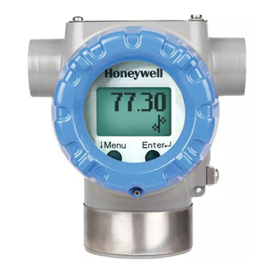
Page 16: Two Integrated-Button Assembly (Standard Display)
Two Integrated-Button Assembly (Standard Display) The iIntegrated two-button assembly for the Standard Display provides the following features and capabilities: • Menu and enter key functionality. • With the menu-driven display: o Comprehensive on-screen menu for navigation. o RMA Configuration – Select PV, Select Unit, Enter LRV, Enter URV, BUNIT. o RMA Calibration o Display Configuration - Contrast o RMA Diagnostics. -
Page 17: Installation And Startup
Installation Site Evaluation Evaluate the site selected for the Remote Indicator installation with respect to the process system design specifications and Honeywell’s published performance characteristics for your particular model. Some parameters that you may want to include in your site evaluation are: •... -
Page 18: Mounting Remote Indicator
Mounting Remote Indicator Remote Indicator models can be attached to a two-inch (50.8 millimeter) vertical or horizontal pipe using Honeywell’s optional pipe mounting bracket. The Remote Indicator can also be wall mounted using Honeywell’s optional wall mounint bracket as shown in Figure 2.3.1... -
Page 19: Figure 6: Mounting Bracket Secured To A Remote Indicator
Figure 6: Mounting Bracket Secured to a Remote indicator 3. Position the bracket on a 2-inch (50.8 mm) horizontal or vertical pipe, and install a “U” bolt around the pipe and through the holes in the bracket. Secure the bracket with (2) M10 hex nuts, (2) flat washers and (2) lock washers provided. -
Page 20: Figure 8: Remote Indicator Secured To A Wall Mounting Bracket
Wall Mount Option - Refer Figure 8 Position the bracket on the mounting surface at the desired location and secure the bracket to the mounting surface using the appropriate hardware (Wall mounting hardware requirements to be determined and supplied by the end user). Figure 8: Remote Indicator Secured to a Wall Mounting Bracket RMA803 Remote Indicator User's Guide Revision 2... -
Page 21: Wiring A Remote Indicator
Overview The Remote Indicator is designed to operate in normal 4-20mA analog mode with 4-20 mA /HART enabled transmitters or DE mode for Honeywell SmartLine transmitters STT250/STT700 in digital and analog modes. For improved noise performance, it is recommended to provide earth ground for both transmitter and RMA housing. -
Page 22: Figure 10: Remote Indicator Connected On The Positive Side Of Loop (Analog Mode)
Figure 10: Remote Indicator connected on the positive side of loop (analog mode) Figure 11: Remote Indicator connected on the negative side of loop (DE mode) Note – The resistor “R” indicates the loop resistor which is needed for HART and DE communication and is typically provided by the user or control system. -
Page 23: Figure 12: De/Analog Terminal Block
Figure 12: DE/ANALOG Terminal Block Figure 13: RMA801 Terminal Block Revision 2 RMA803 Remote Indicator User's Guide... -
Page 24: Wiring Procedure
2.4.3 Wiring Procedure Figure 12, for parts locations. Loosen the end cap lock using a 1.5 mm Allen wrench. Remove the end cap cover from the terminal block end of the electronics housing. Feed loop power leads through one end of the conduit entrances on either side of the electronics housing. -
Page 25: Performance Specifications
+/- 0.01 % of Span /° C (+/- 1 digit) Temperature Effect Same as transmitter* • Reproduces the transmitter signal exactly to within its Honeywell Digital (DE) Mode resolution Display 6 digits numeric indication Display Resolution 0.01 unit for reading range (-999 to 999) 0.1 unit for reading range (-9999 to -1000) or (1000 unit to 9999). -
Page 26: Operation
SCT/MCT Toolkit then RMA parameters will be auto-configured. For every configuration change in the transmitter, it is recommended to perform the database upload to reflect te changes in RMA801. Figure 14: RMA HANDHELD WIRING – DE MODE (Analog/Digital) -
Page 27: Configuration Using Standard Display
Configuration using Standard Display For analog/HART transmitter, match the RMA801 parameters to the connected transmitter parameters using the Standard Display menu. The Remote Indicator’s two-button interface provides a user interface and an ability to configure the display parameters. The figure below shows the location of the two-button option and the labels for each button. -
Page 28: Menu Navigation
4.3.1 Menu Navigation ↵ ↵ ↵ ↵ The user must press button to call up the Main Menu. To exit the Main Menu and return to the PV display screen, select <EXIT>. ↵ ↵ ↵ ↵ Use the button to scroll through the list of menu items. Press the button to select an item for data entry or activation. -
Page 29: Editing A Numeric Value
4.3.3 Editing a Numeric Value Editing of a numeric value is a digit-by-digit process, starting with the left-most digit. ↵ ↵ ↵ ↵ 1. Press to begin the edit process. 2. The Standard Display will show the current value of the item on the lower line, left justified. ↵... -
Page 30: Table 5: Rma801: Standard Display Menu
Table 5: RMA801: Standard Display Menu Menu Parameter Parameter Values Desription Operation Use the selection when RMA is Pressure (PRESURE) Press ↵ to connected to Pressure transmitter enter menu Use the selection when RMA is Temperature (TEMP) connected to Temperature... - Page 31 This selection allows the user to perfom calibration for 4 mA. Input Calibration Note: You must connect a current Low Point meter to the transmitter to monitor Press ↵ to [CAL Lo ] Input Calibration Low Point the loop output. And the enter menu device/loop current need to set to selection...
- Page 32 Press ↵ to enter Menu Adjust the LCD contrast level. selection Contrast Range from » (1) to »»»»»»»»» »»»»» [CNTRST] Menu to Default: »»»»»»»(7) select level. ↵ to Enter RMA Diagnostic Messages: RAM ERR ROM ERR FLW FLT Press ↵ to RAM CRC enter Menu BRW RST...
-
Page 33: Standard Display Abbreviations
4.3.6 Standard Display Abbreviations: Table 6: The Standard Display abbreviations The abbreviations will be seen during configuration or any alarm conditions. Abbreviation Meaning Recommended action Wrt Prtd “Write Protected” Change the mode to un protected and Device is in write protect mode then configure the device Not Sprtd “Not Supported”... -
Page 34: Changing The Write Protect Direction
Changing the Write protect Direction On the Remote Indicator, there is no failsafe jumper selection but there is a write protect jumper. The bottom jumper sets the write protect. The default setting is OFF (un-protected). When set to the ON (protected) position, changed configuration parameters cannot be written to the Remote Indicator. -
Page 35: Table 7: Write Protect Jumpers
Table 7: Write Protect Jumpers Image Description Write Protect = OFF (Not Protected) Write Protect = ON (Protected) 1. Ensure the Remote indicator is disconntecd form the loop. 2. Loosen the end cap lock, and unscrew the end cap from the display side of the Remote Indicator housing. -
Page 36: Monitoring The Standard Display
Monitoring the Standard Display Table 8: Standard Display with PV Format Display Indications Display Messages What It Means Diagnostic Messages BAD-Tx Transmitter critical diagnostic condition present These messages are This message is displayed any time a critical diagnostic is present in the displayed in the lower transmitter. - Page 37 Error messages Following are the error messages displayed on the RMA during respective Table 6 fault conditions in diagnostic menu ”RMA DG”. See for more details. RAM ERR (RAM Corrupt) ROM ERR (ROM Corrupt) FLW FLT (Flow failed) RAM CRC (RAM crc failure) BRW RST ( Brown out reset)
- Page 38 PV Value User configurable. This field has 6 characters. For notes on PV, Maximum allowable numeric value of 999999 or -999999. see section 7.3.1 If fractional decimals are configured, the fractional positions will be dropped as required. If the PV exceeds the values above limits, the PV is divided by 1000 and “K”...
-
Page 39: Maintenance
The RMA801 Remote Indicator does not require any specific maintenance at regularly scheduled intervals. Maintenance of the RMA801 is limited to ensuring that connections, seals and mounting are tight and secure. There are no moving parts or adjustments and hence no reason to open the field housing except to inspect for corrosion or conductive dust entry which could later affect reliable operation. - Page 40 Please take appropriate steps to avoid ESD damage when handling the Communication and Display Module assemblies Procedure to replace the COMM/DISPLAY module: Disconnect Remote Indicator from the loop (this in accordance with Class 1 Div 1 Explosionproof and Class 1 Div 2 environments). Loosen the end cap lock, and unscrew the end cap from the electronics side of the Remote Indicator housing.
-
Page 41: Upgrading The Firmware
Upgrading the firmware To upgrade the firmware of the Remote Indicator, please use the SmartLine Anytime Tool (SAT). See SmartLine Anytime Tool (SAT) User’s Guide, # 34-TT-25-12 to download the firmware Refer Below link for more detials https://www.honeywellprocess.com/en-US/explore/products/instrumentation/transmitter-configuration- tools-and-accessories/Pages/field-instrumentation-configuration-and-support-files.aspx and select the Software tab Firmware upgrade Tool for SmartLine devices to download the .zip file direcly Revision 2... -
Page 42: Calibration
1. RMA801 device 2. HART device 3. HART Host (Handheld 475/Hart server) 4. Reference DMM (optional) Connect RMA801 device is in series with HART transmitter. Steps: 1. Connect HART host to the HART device and keep HART device in fixed current mode. -
Page 43: Remote Indicator Calibration When Connected In Loop With De Tansmitter
2. STT700/STT250 DE device 3. DE Host (SCT3000/MCT404) 4. Reference DMM (optional) Connect RMA801 device in series with STT700/250 DE device and connect DE host to the device. Steps: 1. Keep device in DE analog mode 2. Connect SCT/MCT tool to the device and upload the devce database. -
Page 44: Troubleshooting
Troubleshooting is performed to determine the cause of the fault by analyzing the device indications or diagnostics messages. If you require assistance, contact your distributor or Honeywell Technical Support. Critical Diagnostics Screens When a critical diagnostic is present in the remote indicator, the Standard Display will display the message as BAD-Tx or BAD-RMA on the bottom line of the LCD. -
Page 45: Fault Conditions And Recommended Corrective Actions
7.2.1 Fault Conditions and recommended Corrective Actions Table 9: Fault Conditions and Recommended Corrective Actions. Condition Analysis Recommenred/Corrective Action Bad transmitter Use a DE communicator to read the If this fault occure in Analog (BAD-Tx) Fault. detailed status information from the mdoe then Check the RMA transmitter. -
Page 46: Security
Security Security guidelines The RMA801 provides several features designed to prevent accidental changes to the device configuration or calibration data. These features include a hardware write protect jumper. These features can be used in combination to provide multiple layers of configuration change protection. -
Page 47: Spare Parts List
Spare Parts List Overview Individually saleable parts for the various Remote Indicator models are listed in this section. Some parts are illustrated for identification. Parts are identified and listed in the corresponding tables as follows: • Individually available parts are indicated in each figure by key number callout. Table 10 is a summarized list of recommended spare parts. -
Page 48: Table 12: Remote Indicator Major Assemblies
Table 12: Remote Indicator Major Assemblies (Refer to Figure 20) Quantity Key No. Part Number Description Per Unit 50049832-501 End Cap, Display (Aluminum) 50049832-521 End Cap, Display (Stainless Steel) 50086421-533 Terminal Module Assy See Fig. 17 50126003-501 Standard Display 30757503-005 Electronics housing seals kit (O-rings) Figure 20: Electronic Housing, Terminal Block End RMA803 Remote Indicator User's Guide Revision 2... -
Page 49: Certifications And Approvals
Certifications and Approvals 10.1 European Directive Information (CE Mark) Revision 2 RMA803 Remote Indicator User's Guide... - Page 50 RMA803 Remote Indicator User's Guide Revision 2...
- Page 51 Revision 2 RMA803 Remote Indicator User's Guide...
- Page 52 RMA803 Remote Indicator User's Guide Revision 2...
- Page 53 Hazardous Locations Certifications AGENCY TYPE OF PROTECTION Electrical Ambient CODE Parameters Temperature Flame-proof and Dust: T6: -50ºC to +65ºC II 2 G Ex db IIC T6..T4 Gb Note 1 T4, T5: -50 ºC to II 2 D Ex tb IIIC T 95 C Db 85ºC Intrinsically Safe:...
- Page 54 AGENCY TYPE OF PROTECTION Electrical Ambient CODE Parameters Temperature Standards: CSA C22.2 No. 0: 2015; CSA C22.2 No. 30: 2016; CSA C22.2 No. 94-M91; CSA C22.2 No. 25: 2017; CSA C22.2 No. 61010-1: 2017; CSA-C22.2No.157: 2016; C22.2 No. 213: 2017; C22.2 No. CSA 60079-0:2015; C22.2 No. 60079-1: 2016; C22.2 No.
- Page 55 Marking ATEX Directive a. General The following information is provided as part of the labeling of the Remote Indicator: Name and Address of the manufacturer The serial number of the Remote Indicator is located on the Meter Body data-plate. The first two digits of the serial number identify the year (02) and the second two digits identify the week of the year (23);...
- Page 56 The ambient temperature range, maximum process temperature and applicable temperature class of the equipment is as follows: RMA801: T4 for -50˚C < Ta < 85˚C RMA803: T4 for -20˚C < Ta < 70˚C d. The RMA800 series enclosure contains aluminum and is considered to present a potential risk of ignition by impact or friction.
- Page 57 Control Drawing: 50089981 Revision 2 RMA803 Remote Indicator User's Guide...
- Page 58 RMA803 Remote Indicator User's Guide Revision 2...
- Page 59 Revision 2 RMA803 Remote Indicator User's Guide...
- Page 60 This page has been intentionally left blank RMA803 Remote Indicator User's Guide Revision 2...
-
Page 61: Index
................15 Configuration using Standard Display ......16 References ..............iv Control Drawing ............46 RMA801 major assembly ..........2 Copyrights, Notices and Trademarks ......iii RMA801 Remote Indicator .......... 1 Critical Diagnostics Screens ........33 Safety Certification Information ........3 Data Entry .............. - Page 62 Specifications are subject to change without notice. For more information To learn more about SmartLine Transmittersrs, visit www.honeywellprocess.com Or contact your Honeywell Account Manager Process Solutions Honeywell 1250 W Sam Houston Pkwy S Houston, USA, TX 77042 Honeywell Control Systems Ltd...
Need help?
Do you have a question about the RMA801 and is the answer not in the manual?
Questions and answers