
Related Manuals for Smeg BPW1260


Summary of Contents for Smeg BPW1260
- Page 1 BPW1260 BPW – BEDPAN WASHERS – Hospital sector USER MANUAL TRANSLATION OF THE ORIGINAL INSTRUCTIONS...
- Page 2 Device Manufacturer and CE mark [ Device Manufacturer and CE mark ] User Manual 193909105 rev.02 BPW1260 Page 2 – 93...
-
Page 3: Table Of Contents
POSITIONING AND FIXING THE DEVICE ................... 31 6.1.1 FIXING TO THE WALL ....................... 31 6.1.2 FIXING TO THE FLOOR ......................32 CONNECTING TO THE ELECTRICITY AND WATER SYSTEMS ..............34 ACCESS TO CONNECTIONS....................... 34 User Manual 193909105 rev.02 BPW1260 Page 3 – 93... - Page 4 LIQUID SUCTION SYSTEM – REPLACING AN EMPTY JERRY CAN ..........38 BASIC OPERATION ........................... 40 CONTROL AREA ..........................40 BPW1260 BUTTONS ......................... 41 DISPLAY AND ICONS ........................42 WITH CYCLE PRESELECTED – INFORMATION ABOUT PROGRAM PARAMETERS ......45 SELECTING A PROGRAM ........................45 STARTING THE PROGRAM .......................
- Page 5 CONNECTIONS TO THE DEVICE ....................89 15.3 ELECTRICAL SYSTEM REQUIREMENTS ..................... 91 15.3.1 Power cable ..........................91 16 WATER CONNECTION REQUIREMENTS ....................92 16.1.1 WATER INTAKE ........................92 16.2 WATER DRAIN REQUIREMENTS ....................... 92 User Manual 193909105 rev.02 BPW1260 Page 5 – 93...
- Page 6 Revision with inclusion of CE0051 mark on front cover, clarification of post- 193909105 12/10/2022 installation electrical connection, updating of preparation of system preparation and interface instructions. 193909105 09/03/2022 First issue Code Rev. Date Notes User Manual 193909105 rev.02 BPW1260 Page 6 – 93...
-
Page 7: Initial Instructions
Illustrations and the colours used in photographs, drawings and the forms which reproduce the display are purely guideline, and intended to ensure that the user correctly understands the operating concepts described in the text. User Manual 193909105 rev.02 BPW1260 Page 7 – 93... -
Page 8: Intended Purpose And Classification
SERIES Key characteristics BPW1260 Free-standing bedpan washer of 60 cm, with manually operated bottom-hinged door INTENDED PURPOSE: treatment of sanitary aids used to contain human waste, in use within hospitals and or care homes, by means of thermal disinfection cycles, to prevent the spread of infectious agents which are a threat to both hospital staff and the final patient. -
Page 9: Contraindications
From Regulation (EU) 2017/745: “[…] confirming the safety and performance throughout the expected lifetime of the device. […]”. User Manual 193909105 rev.02 BPW1260 Page 9 – 93... -
Page 10: Standard En Iso 15883
The device has a physical port for the insertion of probes. The port can only be accessed by authorised engineers, in accordance with the procedure established by the Manufacturer. If probes are utilised by the user or other parties, the use of wireless probes (datalogger or similar) is recommended. User Manual 193909105 rev.02 BPW1260 Page 10 – 93... -
Page 11: Definition: "Responsible Body" In Relation To The Device
Staff training should be checked regularly. The installation engineer is responsible for ensuring that the device operates correctly after commissioning. Safety information supplied in compliance with IEC61010-2-040. User Manual 193909105 rev.02 BPW1260 Page 11 – 93... -
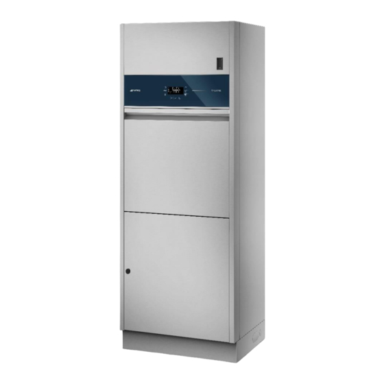
Page 12: Presentation
The device’s user interface consists of an LCD screen and touch buttons for user interaction. DOOR COMPARTMENT USB PORT LCD INTERFACE WITH TOUCH BUTTONS CHAMBER SANITARY SUPPORT BOTTOM-HINGED DOOR DOOR TO BOTTOM COMPARTMENT LOCATION OF MAIN SWITCH (INSIDE COMPARTMENT) PRODUCT JERRY CAN CONTAINER (INSIDE COMPARTMENT) User Manual 193909105 rev.02 BPW1260 Page 12 – 93... -
Page 13: Product Configuration
Each of the models covered by this manual is identified by a unique commercial name. The name is constructed by combining A – the name of the relevant series: “BPW1260” B – appropriate suffixes which refer to the model’s specific characteristics. - Page 14 This system, known as BPW-DRY, is not intended to completely remove all water residues from the processed load. User Manual 193909105 rev.02 BPW1260 Page 14 – 93...
-
Page 15: Optional Components
Set for three-phase connection of the device without neutral (fitted in the factory or on site by authorised engineers). BPW-EC-3 905564 The optional accessory consists of the specific power supply cable and the preparation of the suitable electrical connections. User Manual 193909105 rev.02 BPW1260 Page 15 – 93... -
Page 16: Bpw-2B - Optional Accessory Which Configures The Device To Wash 2 Bedpans
The system consists of: Fan-assisted cooling motor HEPA H13 filter Prefilter Connection systems Guideline illustration [the system is installed inside the device and is not visible from the outside] User Manual 193909105 rev.02 BPW1260 Page 16 – 93... -
Page 17: Bpw-Drainfloor - Optional Accessory For Adapting The Device For Connection To A Floor Drain
The optional accessory consists of the following components: Floor drain trap Internal stiffener ring Connection collar with screws Extension hose with socket Guideline illustration [the system is installed inside the device and is not visible from the outside] User Manual 193909105 rev.02 BPW1260 Page 17 – 93... -
Page 18: Bpw-P1H - Optional P1 Detergent Dispensing System
The user can easily remove the tank for regular cleaning. Guideline illustration [the system is installed inside the device and is not visible from the outside] User Manual 193909105 rev.02 BPW1260 Page 18 – 93... -
Page 19: Bpw-232Print - Optional Rs232 Port For Remote Printer Connection
PC used for connection, minimum requirements: RJ45 port, Microsoft Windows 32 or measures 64bit operating system, Windows 7 or higher with Framework 4.0 or higher installed against and updated. User Manual 193909105 rev.02 BPW1260 Page 19 – 93... -
Page 20: Bpw-Printe2 - Optional Cycle Report And Machine Parameters Printer
Guideline illustration Guideline illustration of the optional Position of the device’s RS232 port. thermal printer. User Manual 193909105 rev.02 BPW1260 Page 20 – 93... -
Page 21: Bpw-Ec-1 - Set Of Components For Connection Of The Device To Single-Phase Power
Cable gland and fixing collar of correct size for cable. The set can be fitted in the factory or on site by authorised engineers. Guideline Power cable illustration Cable gland and collar User Manual 193909105 rev.02 BPW1260 Page 21 – 93... -
Page 22: Bpw-Ec-3 - Set Of Components For Connection Of The Device To Single-Phase Power
• Fuses of the correct rating. N.B.: the set can be fitted in the factory or on site by authorised engineers, following the electrical system diagram provided Guideline Power cable illustration Fuses User Manual 193909105 rev.02 BPW1260 Page 22 – 93... -
Page 23: Safety And Precautions For Use
Do not touch live parts if the power supply has not been disconnected. Specific Notes and Precautions for the Hospital Sector. USB port – Data communication and programming of the device. Transport, storage and unpacking precautions. Biological hazard. User Manual 193909105 rev.02 BPW1260 Page 23 – 93... - Page 24 EC CERTIFICATION issued by IMQ (“0051” is the code number of the notified body IMQ). Medical Device – Symbol on product's technical dataplate. (ISO 15223-1 – Symbol 5.7.7). User Manual 193909105 rev.02 BPW1260 Page 24 – 93...
-
Page 25: General Warnings
These maintenance operations are not covered by the product Warranty, which does not include the replacement of components which deteriorate due to normal wear and tear. User Manual 193909105 rev.02 BPW1260 Page 25 – 93... - Page 26 ACCESS TO THE DEVICE AT END-OF-LIFE” section Once decommissioned, the device must be rendered unusable. Cut the power supply cable after removing the plug / disconnecting the cable from the power socket. User Manual 193909105 rev.02 BPW1260 Page 26 – 93...
-
Page 27: Warnings Concerning Connection To An It Network
Equipment used for diagnostic or therapy purposes and particularly sensitive to electromagnetic interference should not be installed in the immediate vicinity of this device. User Manual 193909105 rev.02 BPW1260 Page 27 – 93... -
Page 28: Warnings For Handling The Device
As far as possible, the product should not be moved around by hand. If manual handling is unavoidable, at least 3 or more people must be used. User Manual 193909105 rev.02 BPW1260 Page 28 – 93... -
Page 29: Precautions For Accessing And Reusing The Device After An Incomplete Cycle And For Accessing The Device At End-Of-Life
Contact authorised technical staff in the event of a failure. User Manual 193909105 rev.02 BPW1260 Page 29 – 93... -
Page 30: Removing The Packaging And Preparing For Handling
Undo the screws which secure the back strip to the surface of the pallet and remove it Undo all the screws fixing the device to the wooden pallet, opening the rear door Guideline illustration of packaging remove phases User Manual 193909105 rev.02 BPW1260 Page 30 – 93... -
Page 31: Positioning And Fixing The Device
Screw the two brackets to the top of the device using the M5 screws provided and slide them out until they fit snugly against the wall. Use 2 anchor bolts diameter 8 mm to fix the brackets to the wall. After fixing, tighten the screws on the top of the device. User Manual 193909105 rev.02 BPW1260 Page 31 – 93... -
Page 32: Fixing To The Floor
Finally, fix the device to the stand with the 4 M8 screws provided (two per side) and the 2 M4 screws for the front (open the door of the bottom compartment to insert the last two.). User Manual 193909105 rev.02 BPW1260 Page 32 – 93... - Page 33 WARNING Any adjustments, maintenance, etc. must be done with the device disconnected from its power supply. User Manual 193909105 rev.02 BPW1260 Page 33 – 93...
-
Page 34: Connecting To The Electricity And Water Systems
This situation is illustrated below. User Manual 193909105 rev.02 BPW1260 Page 34 – 93... -
Page 35: Connecting The Drain Trap
SCREW TIE FITTING CHAMBER TANK OVERFLOW DRAIN PIPE DRAIN TRAP Ø110 MM User Manual 193909105 rev.02 BPW1260 Page 35 – 93... - Page 36 N.B.: to simplify this procedure, the drain trap can be disconnected from the chamber by undoing the screw tie fitting, taking care to reconnect it once the drain connection has been made. User Manual 193909105 rev.02 BPW1260 Page 36 – 93...
-
Page 37: Commissioning
6. The authorised engineer can proceed with complete verification and recording of correct operation on the user’s premises, accordance with the Manufacturer’s procedure (ref. SR152). The device is now ready for use. User Manual 193909105 rev.02 BPW1260 Page 37 – 93... -
Page 38: Usingdetergents
STANDARD configuration. Fitting the detergent intake pipe to the jerry can. Fit the rubber cap over the Fig. 1 – top of the can for a perfect, secure connection. The pipe is supplied complete with intake filter. User Manual 193909105 rev.02 BPW1260 Page 38 – 93... - Page 39 Jerry cans must be securely positioned inside the bottom compartment with the intake nozzles inserted. Example of position of jerry cans inside bottom compartment User Manual 193909105 rev.02 BPW1260 Page 39 – 93...
-
Page 40: Basic Operation
The touch buttons for interaction with the device are beside and underneath the display. Different functions can be obtained by pressing a button briefly or holding it down (2 seconds). BPW1260 CONTROL PANEL Fig. 2 – Control panel. Display area in centre, control buttons at the sides and bottom. -
Page 41: Bpw1260 Buttons
BPW1260 BUTTONS Icon Main function Secondary function Device On/Off. N.B.: the button is not a main switch; the device is still powered up even in Off With cycle in progress, press condition. briefly to interrupt cycle (see When in standby: hold down to switch on... -
Page 42: Display And Icons
The screens shown below mainly refer to the layout of model BPW1260. The same remarks and procedures also apply for the other models covered by the manual, unless otherwise specified. DISPLAY AND ICONS The central display consists of two main lines, which show program and machine parameter information, and a series of icons used for information about the cycle in progress and the status of the device. - Page 43 Drying filter change required. mark: filter about to expire. On (not flashing) without exclamation On (not flashing) with exclamation mark: mark: filter about to expire. the number of hours after which the User Manual 193909105 rev.02 BPW1260 Page 43 – 93...
- Page 44 Flashing: data being downloaded to the device (e.g. firmware update). Flashing: parameters being saved. On (not flashing): saving completed. The icon remains on for t_s=3 seconds. Icon off: when no data saving is in progress. User Manual 193909105 rev.02 BPW1260 Page 44 – 93...
-
Page 45: With Cycle Preselected - Information About Program Parameters
Program Pr 08 appears on the display with “CLOST” on the second line and the Clostridium treatment icon illuminates When the cycle starts CLOST is replaced by info as for all the other cycles. User Manual 193909105 rev.02 BPW1260 Page 45 – 93... -
Page 46: Starting The Program
The A icon is illuminated when the parameter’s value appears on the second line. Example of display of Time remaining to end of cycle. The clock icon is illuminated. User Manual 193909105 rev.02 BPW1260 Page 46 – 93... -
Page 47: Interrupting The Current Program
Program completed successfully: the word END appears (not flashing) on the second line of the display. Unlock the door with the “padlock” button (P7) to open the door and remove the load. User Manual 193909105 rev.02 BPW1260 Page 47 – 93... - Page 48 (tank pumpout in progress). Once pumpout of the tank is complete, goes out and the start/stop icon illuminates. During this phase, all buttons are disabled and the “Start / Stop” icon remains off. User Manual 193909105 rev.02 BPW1260 Page 48 – 93...
-
Page 49: Program Completed With Anomalies - Warnings
After the first one has been acknowledge the system moves on to the second one, and so on. The list of Warnings and their meanings is provided in the “Warning Table” (section 13.1.1): each is identified by the letter “W” followed by the specific number. User Manual 193909105 rev.02 BPW1260 Page 49 – 93... -
Page 50: Alarms - Serious Anomalies
R + W Setup Peristaltic user PUV1 ON, OF R + W R + W R + W values Peristaltic user PUV2 ON, OF R + W R + W values User Manual 193909105 rev.02 BPW1260 Page 50 – 93... - Page 51 R + W R + W Reset filter hours R + W R + W Reset Reset cycles before R + W R + W maintenance counter Output activation IOTEC and input display User Manual 193909105 rev.02 BPW1260 Page 51 – 93...
-
Page 52: Accessing The Menus
P8, which scroll from 0, 1 ... 9 in rotation. 2. To move to the next character on the right, press When done: press button P5 confirm. Once the password has been entered and access granted, the “gears” icon illuminates. User Manual 193909105 rev.02 BPW1260 Page 52 – 93... -
Page 53: Access To The Setup And Dependent Headings
Default is “EN” printout in English. P2 and P8 scroll through the other languages available: IT, EN, FR, DE, ES, PT, PL. User Manual 193909105 rev.02 BPW1260 Page 53 – 93... - Page 54 NT-OF (default): LAN connection absent. NT-ON: LAN connection present. It can only be modified by the authorised engineer. DEM – Display Easy Mode DEM: ON (default) display easy mode DEM: OF – full display User Manual 193909105 rev.02 BPW1260 Page 54 – 93...
- Page 55 EVLP2 – Two bedpan valve enabling: parameter that enables use of the valve for processing the bedpan 2 (EVLPD2). This parameter can be modified by the superuser. Default “ON”. If “OF” all phases involving EVLPD2 are bypassed User Manual 193909105 rev.02 BPW1260 Page 55 – 93...
- Page 56 Parameter which enables the user to run the CLOSTRIDIUM program This parameter can be modified by the engineer and/or via WDConnect. P1 and the relative flowswitch must be installed for the “CLO” program to be enabled. User Manual 193909105 rev.02 BPW1260 Page 56 – 93...
-
Page 57: Setting The Time - Clock Menu
The digits flash while they are being edited: increase and decrease using buttons P2 and P8. Use buttons P4 or P6 to switch from setting to minutes to hours. Confirm with P5 when done. User Manual 193909105 rev.02 BPW1260 Page 57 – 93... -
Page 58: Setting The Date - Date Menu
P5 is pressed to confirm. 10.5 DRY HOUR COUNTER – DryH Description Illustration Function DryH is read-only and displays the operating hours of the drying system. 10.6 ABSOLUTE HOUR COUNTER – Count User Manual 193909105 rev.02 BPW1260 Page 58 – 93... -
Page 59: Program Enabling - Pr En
Confirm with button P5. Press buttons P4 and P6 to scroll the programs. The parameter can be edited by the Superuser, from a minimum of 60 to a maximum of 6000. Settings are in steps of: User Manual 193909105 rev.02 BPW1260 Page 59 – 93... -
Page 60: Reset
To restore the configuration and equipment values to the Factory values, set and confirm “FV”. [change value with P2/P8, confirm with P5] User Manual 193909105 rev.02 BPW1260 Page 60 – 93... -
Page 61: Df - Dryer Filter - Relative Decremental Counter
RM-90 (900 cycles remaining), RM-89 (from 899 to 890 cycles remaining) … , RM-00 (from 9 cycles remaining to 0), RMW:01 (from 1 to 9 cycles after zero), RMW:02 etc. up to RMW:99 (after which the counter stops). User Manual 193909105 rev.02 BPW1260 Page 61 – 93... -
Page 62: Memory And Printout
The value can be reset by a Smeg authorised engineer: hold down P5. The initial value of RM-90 is restored and the countdown restarts. 10.10 MEMORY AND PRINTOUT Terms and abbreviations used and their meanings Cold water. Example: “Load CW / 23L” means: load cold water, 23 litres. - Page 63 ..... . . * * * * * * * * * * * * * * * * * * * * * * User Manual 193909105 rev.02 BPW1260 Page 63 – 93...
-
Page 64: Editing Custom Programs
3. appear at the end of the list of non-editable factory-set programs; As envisaged by the reference standards [EN ISO 15883-1], if a process parameter is modified, specific performance qualification procedures must be repeated. Consult the authorised after-sales service for further information. User Manual 193909105 rev.02 BPW1260 Page 64 – 93... -
Page 65: Recommended Detergents And Important Notices
Neodisher® Manufacturer: Chemische Fabrik Dr. Weigert GmbH MEDICLEAN Product codes: 405033, 405035, 405030 [depending on jerry can size] FORTE P2 – Acid neutralising agents DEKAL100 Descaler, concentrated liquid containing organic acids User Manual 193909105 rev.02 BPW1260 Page 65 – 93... - Page 66 The device’s responsible body must dispose of detergent residues and containers in accordance with the relevant national or local legislation. FLAMMABILITY Always refer to detergent technical data sheets to assess products’ flammability. Do not use flammable products in the device. User Manual 193909105 rev.02 BPW1260 Page 66 – 93...
-
Page 67: Preparing The Load For The Washing And Disinfection Cycle
Support for 1 bedpan and 2 urine bottles, also R-1B2P-01 905428 suitable for processing 4 urine bottles. Support for 2 bedpans, also suitable for processing 1 bedpan and 2 urine bottles or 4 R-2B-01 905429 urine bottles. User Manual 193909105 rev.02 BPW1260 Page 67 – 93... -
Page 68: Standard Support R-1B2P-01
Configuration B: 4 urine bottles Configuration A Configuration B The bedpan (if present) must always be placed on the left, with the urine bottles occupying the 2 positions on the right. User Manual 193909105 rev.02 BPW1260 Page 68 – 93... -
Page 69: Support For 2 Bedpans R-2B -01
Configuration C Configuration D Configuration E Configuration F N.B.: the support for 2 bedpans R-2B -01 can only be used if the device is fitted with optional accessory BPW-2B (code 905423). User Manual 193909105 rev.02 BPW1260 Page 69 – 93... -
Page 70: Alarms, Warning And Device Response To Blackouts
N.B.: some events may be classified as alarms or warnings depending on how the product’s parameters are set. The full identification provided on the display defines their status. Example: W 41 -> Warning 41 AF41 -> Alarm 41 User Manual 193909105 rev.02 BPW1260 Page 70 – 93... -
Page 71: Warnings
The filter must be replaced by authorised technical staff. Device maintenance Routine maintenance required. These are inspection and maintenance operations which must be performed by authorised staff to keep the device safe and in good working order. User Manual 193909105 rev.02 BPW1260 Page 71 – 93... -
Page 72: Warning Table
This alarm does not appear on the Contact the after-sales service to have maintenance performed W 93 Display but is recorded in the on the product. device memory; the relative LED illuminates on the display. User Manual 193909105 rev.02 BPW1260 Page 72 – 93... -
Page 73: Alarms
At the end of the reset, the interface shows the “FAIL” screen, to clearly indicate that the cycle which was running previously has failed. Reset cycle in response to an alarm event User Manual 193909105 rev.02 BPW1260 Page 73 – 93... - Page 74 2. Disconnect the device from the power supply. 3. Check that the device’s connections (electricity and water) are correct and there have been no changes from the initial installation conditions. 4. Contact the After-Sales Service. User Manual 193909105 rev.02 BPW1260 Page 74 – 93...
-
Page 75: Alarm Table
Anomaly in opening of washing AF:25 the alarm does not disappear, follow the RESET solenoid valves PROCEDURE. In standby status, the alarm resets automatically if its AF:27 Tank does not empty. causes are eliminated. User Manual 193909105 rev.02 BPW1260 Page 75 – 93... - Page 76 RESET PROCEDURE. User: follow the DEFAULT PROCEDURE described above. If Restore fail. Problem on the AF:78 the alarm does not disappear, follow the RESET motherboard. PROCEDURE. User Manual 193909105 rev.02 BPW1260 Page 76 – 93...
- Page 77 Make the device safe and contact the after-sales service. tripped User: follow the DEFAULT PROCEDURE described above. If AF:332 Generator does not fill the alarm does not disappear, follow the RESET PROCEDURE. User Manual 193909105 rev.02 BPW1260 Page 77 – 93...
-
Page 78: Cleaning And Maintenance
• the bottom door of the detergent compartment must be carefully closed on completion of cleaning operations. User Manual 193909105 rev.02 BPW1260 Page 78 – 93... -
Page 79: If The Device Is To Be Out Of Use
Disconnect the power supply. • Turn off the water intake taps. • When restarted, the device prompts the user to perform an automatic washing and thermal disinfection cycle. Confirm with the “confirm” button (P5). User Manual 193909105 rev.02 BPW1260 Page 79 – 93... -
Page 80: Reusing The Device After A Period Out Of Use
Confirm with the “confirm” button (P5). Confirming performance of a thermal disinfection cycle with no load before using the device is highly recommended if it has been out of use for 24 hours or more. User Manual 193909105 rev.02 BPW1260 Page 80 – 93... -
Page 81: Maintenance And Routine Check Time Intervals
10. Performance of a complete operating cycle, including the cooling/drying phase, to check for any leaks or malfunctions. WARNING The manufacturer declines all responsibility in the event of device malfunctions, or injury or damage, arising from the failure to comply with the above recommendations. User Manual 193909105 rev.02 BPW1260 Page 81 – 93... -
Page 82: Troubleshooting
If the display does not reset correctly and remains "dead": contact the after-sales service, as no procedures are possible on the device if the interface is not active and correctly operational. If the problem persists after following the troubleshooting instructions above, call your authorised after-sales service. User Manual 193909105 rev.02 BPW1260 Page 82 – 93... -
Page 83: Installation
Positioning of the device in the installation area. The device's characteristics and positioning and installation instructions are provided below. [The customer is also provided with the specific document – “Installation Requirements for BPW1260”.] 15.1 TECHNICAL CHARACTERISTICS 15.1.1 Water connections “CW”... -
Page 84: Electrical Connections
40 °C. Installation category (or surge category) Electrical insulation class (ref. IEC 61140) Degree of pollution Heat emission – device to room, max 700 W Max noise level <60 dB (A) User Manual 193909105 rev.02 BPW1260 Page 84 – 93... -
Page 85: Weight Of Devices And Stainless Steel Materials
EN 62366-1:2015 EN 61010-1:2010 /A1:2019/AC:2019-04, EN 61010-1:2010/A1:2019 EN IEC 61010-2-040:2021 EN IEC 61326-1:2021 EN IEC 63000:2018 EN 15223-1:2021 The following standards are applied to the system: EN ISO 13485:2016 + A11:2021 User Manual 193909105 rev.02 BPW1260 Page 85 – 93... -
Page 86: Product Dimensions And Drain Connection
The minimum height to be complied with is 370 mm above the ground. User Manual 193909105 rev.02 BPW1260 Page 86 – 93... -
Page 87: Floor Drain
15.2.2 FLOOR DRAIN Simplified diagram, overall dimensions of product with floor drain User Manual 193909105 rev.02 BPW1260 Page 87 – 93... -
Page 88: Connections Area - Electricity And Water
If the connection cannot be kept within the area shown, optional longer hoses (L=3.2 m) can be supplied to order. They can be ordered with kit code 905130 – TASF (blue hose, cold water) and 905131 – TASC (red hose, hot water) Simplified drawing: electrical and water intake connections User Manual 193909105 rev.02 BPW1260 Page 88 – 93... -
Page 89: Connections To The Device
Peristaltic pump P1 intake hose and P1 jerry can detergent level sensor cable Peristaltic pump P2 intake hose and P2 jerry can detergent level sensor cable RS-232 port for printer connection USB port for data upload and download LAN port BPW1260 rear view User Manual 193909105 rev.02 BPW1260 Page 89 – 93... - Page 90 BPW1260 front view The position of the USB port is marked BPW1260 top view The positions of the RS232 and LAN port are marked REAR FRONT User Manual 193909105 rev.02 BPW1260 Page 90 – 93...
-
Page 91: Electrical System Requirements
H07RN-F 5 x 2.5 mm (5G2,5), 450/750 V, (three-phase with neutral version) H07RN-F 4 x 2.5 mm (4G2.5), 450/750 V, (three-phase without neutral version) H07RN-F 3 x 2.5 mm (3G2.5), 450/750 V, (single-phase version) User Manual 193909105 rev.02 BPW1260 Page 91 – 93... -
Page 92: Water Connection Requirements
• Use of a drain pipe of 110 mm diameter is recommended. • No extensions must be added to the drain hose supplied with the device. Any extensions may case problems of flowback into the chamber. User Manual 193909105 rev.02 BPW1260 Page 92 – 93... - Page 93 After-Sales Service (Service and Technical Information) contact: Single contact number for Italy +39 0522.160.60.50 Email: assistenza.instruments@smeg.it • For sales information: Email: instruments@smeg.it International Customers Please contact your Local Smeg Distributor or write an email to service.instruments@smeg.it User Manual 193909105 rev.02 BPW1260 Page 93 – 93...
Need help?
Do you have a question about the BPW1260 and is the answer not in the manual?
Questions and answers