
Subscribe to Our Youtube Channel
Related Manuals for Smeg BPW4260


Summary of Contents for Smeg BPW4260
- Page 1 BPW1260 BPW4260 BPW – BEDPAN WASHERS – Hospital sector USER MANUAL TRANSLATION OF THE ORIGINAL INSTRUCTIONS...
- Page 2 Device Manufacturer and CE mark [ Device Manufacturer and CE mark ] User Manual 193909105 rev.04 BPW1260 – BPW4260 Page 2 – 107...
-
Page 3: Table Of Contents
DEFINITION: “RESPONSIBLE BODY” IN RELATION TO THE DEVICE ..........11 INTENDED USER AND SUPERUSER ....................11 PRESENTATION ............................12 BPW1260 ............................12 BPW4260 ............................13 PRODUCT CONFIGURATION ........................14 Key to symbols ..........................14 Table of features ..........................15 Optional components ........................16 4.3.1... - Page 4 PLACING AND FIXING THE DEVICE ON THE STAND ..............35 CONNECTING TO THE ELECTRICITY AND WATER SYSTEMS ..............37 ACCESS TO CONNECTIONS....................... 37 ELECTRICAL CONNECTION OF PEDAL BUTTON (FOR BPW4260 MODELS ONLY) ......38 CONNECTING THE DRAIN TRAP ....................... 39 COMMISSIONING ............................ 41 USINGDETERGENTS .........................
- Page 5 MAINTENANCE AND ROUTINE CHECK TIME INTERVALS ..............91 14.5.1 DAILY ............................91 14.5.2 WEEKLY ............................ 91 14.5.3 EVERY SIX MONTHS ......................... 91 14.5.4 EVERY YEAR ..........................91 14.6 TROUBLESHOOTING ........................92 User Manual 193909105 rev.04 BPW1260 – BPW4260 Page 5 – 107...
- Page 6 “Fill” (Previously “Pr 10”). [Master fw version 5.22]. 193909105 23/02/2023 Addition of parts referring to BPW4260 with automatic door opening. 193909105 18/01/2023 Updating of manual for publication. Revision with inclusion of CE0051 mark on front cover, clarification of post-...
-
Page 7: Initial Instructions
Illustrations and the colours used in photographs, drawings and the forms which reproduce the display are purely guideline, and intended to ensure that the user correctly understands the operating concepts described in the text. User Manual 193909105 rev.04 BPW1260 – BPW4260 Page 7 – 107... -
Page 8: Intended Purpose And Classification
It is essential to check the compatibility of the load for treatment with the specific washing cycle chosen, in terms of the maximum temperatures reached and the chemicals used. User Manual 193909105 rev.04 BPW1260 – BPW4260 Page 8 – 107... -
Page 9: Contraindications
From Regulation (EU) 2017/745: “[…] confirming the safety and performance throughout the expected lifetime of the device. […]”. User Manual 193909105 rev.04 BPW1260 – BPW4260 Page 9 – 107... -
Page 10: Standard En Iso 15883
Manufacturer. If probes are utilised by the user or other parties, the use of wireless probes (datalogger or similar) is recommended. User Manual 193909105 rev.04 BPW1260 – BPW4260 Page 10 – 107... -
Page 11: Definition: "Responsible Body" In Relation To The Device
Staff training should be checked regularly. The installation engineer is responsible for ensuring that the device operates correctly after commissioning. Safety information supplied in compliance with IEC61010-2-040. User Manual 193909105 rev.04 BPW1260 – BPW4260 Page 11 – 107... -
Page 12: Presentation
COMPARTMENT USB PORT LCD INTERFACE WITH TOUCH BUTTONS CHAMBER SANITARY SUPPORT BOTTOM-HINGED DOOR DOOR TO BOTTOM COMPARTMENT LOCATION OF MAIN SWITCH (INSIDE COMPARTMENT) PRODUCT JERRY CAN CONTAINER (INSIDE COMPARTMENT) User Manual 193909105 rev.04 BPW1260 – BPW4260 Page 12 – 107... -
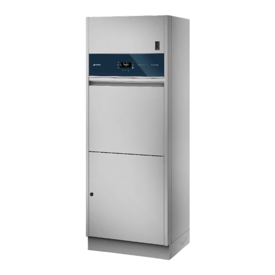
Page 13: Bpw4260
BPW4260 BPW4260 models have an automatic door. The device’s user interface consists of an LCD screen and touch buttons for user interaction. There are also 3 touchless sensors for starting the 3 main programs and a fourth sensor which activates opening/closing of the loading door. -
Page 14: Product Configuration
The name is constructed by combining A – the name of the relevant series: “BPW1260”: manual door opening. “BPW4260”: automatic door opening. B – appropriate suffixes which refer to the model’s specific characteristics. The suffixes are applied in a fixed order. -
Page 15: Table Of Features
This system, known as BPW-DRY, is not intended to completely remove all water residues from the processed load. User Manual 193909105 rev.04 BPW1260 – BPW4260 Page 15 – 107... -
Page 16: Optional Components
Additional temperature probe for reading of temperature in top BPW-SONDPT XXXXXX of chamber. Main switch on board the machine, inside the bottom panel BPW-MSWITCH 905612 User Manual 193909105 rev.04 BPW1260 – BPW4260 Page 16 – 107... -
Page 17: Bpw-2B - Optional Accessory Which Configures The Device To Wash 2 Bedpans
The system consists of: Fan-assisted cooling motor HEPA H13 filter Prefilter Connection systems Guideline illustration [the system is installed inside the device and is not visible from the outside] User Manual 193909105 rev.04 BPW1260 – BPW4260 Page 17 – 107... -
Page 18: Bpw-Drainwall - Optional Accessory For Adapting The Device For Connection To A Wall Drain
• Connection collar with screws • Elbow with seal Extension hose with socket • Guideline illustration [the system is installed inside the device and is not visible from the outside]. User Manual 193909105 rev.04 BPW1260 – BPW4260 Page 18 – 107... -
Page 19: Bpw-Drainfloor - Optional Accessory For Adapting The Device For Connection To A Floor Drain
Floor drain trap Internal stiffener ring Connection collar with screws Extension hose with socket Guideline illustration [the system is installed inside the device and is not visible from the outside] User Manual 193909105 rev.04 BPW1260 – BPW4260 Page 19 – 107... -
Page 20: Bpw-P1H - Optional P1 Detergent Dispensing System
The user can easily remove the tank for regular cleaning. Guideline illustration [the system is installed inside the device and is not visible from the outside] User Manual 193909105 rev.04 BPW1260 – BPW4260 Page 20 – 107... -
Page 21: Bpw Rspacer - 15 Cm Filler Panels For Screw-Mounting On Rear Of Device
• The port is on the top of the device. • This optional accessory must be combined with the printer offered, BPW-PRINTE2. N.B.: this optional accessory does not include the remote printer. Guideline illustration User Manual 193909105 rev.04 BPW1260 – BPW4260 Page 21 – 107... -
Page 22: Bpw-Lani - Optional Communication Port Unit: Lan And Rs232
Proprietary application for communication with devices – distributed by the manufacturer. In addition to the security features of the device, the product’s user instructions direct the healthcare facility to adopt the appropriate computer security and access control/authorisation procedures. User Manual 193909105 rev.04 BPW1260 – BPW4260 Page 22 – 107... -
Page 23: Bpw-Printe2 - Optional Cycle Report And Machine Parameters Printer
Cable gland and fixing collar of correct size for cable. The set can be fitted in the factory or on site by authorised engineers. Guideline Power cable illustration Cable gland and collar User Manual 193909105 rev.04 BPW1260 – BPW4260 Page 23 – 107... -
Page 24: Bpw-Ec-3 - Set Of Components For Connection Of The Device To Single-Phase Power
• Fuses of the correct rating. N.B.: the set can be fitted in the factory or on site by authorised engineers, following the electrical system diagram provided Guideline Power cable illustration Fuses User Manual 193909105 rev.04 BPW1260 – BPW4260 Page 24 – 107... -
Page 25: Bpw-Sondpt - Additional Temperature Probe
Name BPW-MSWITCH Code 905612 Description Optional electrical main switch. The main switch is installed inside the bottom compartment. The optional accessory comprises: • Main switch • Cabling. Guideline illustration User Manual 193909105 rev.04 BPW1260 – BPW4260 Page 25 – 107... -
Page 26: Safety And Precautions For Use
Do not touch live parts if the power supply has not been disconnected. Specific Notes and Precautions for the Hospital Sector. USB port – Data communication and programming of the device. Transport, storage and unpacking precautions. Biological hazard. User Manual 193909105 rev.04 BPW1260 – BPW4260 Page 26 – 107... - Page 27 Medical Device – Symbol on product's technical dataplate. (ISO 15223-1 – Symbol 5.7.7). Where relevant, the symbol “CH REP” in the product marking indicates the name and address of the Swiss authorised representative. User Manual 193909105 rev.04 BPW1260 – BPW4260 Page 27 – 107...
-
Page 28: General Warnings
The device should also be switched off and back on with the main switch before restarting normal use. [The main switch may be incorporated in the device or in the electrical panel, depending on your device’s configuration]. User Manual 193909105 rev.04 BPW1260 – BPW4260 Page 28 – 107... - Page 29 Use of the device in combination with chemicals other than those recommended by the manufacturer may cause a deterioration of its performance and lead to problems regarding the safety of the device, its operators and the environment. User Manual 193909105 rev.04 BPW1260 – BPW4260 Page 29 – 107...
-
Page 30: Warnings Concerning Connection To An It Network
- Malware protection to prevent the execution of unauthorised code; - Training to raise awareness of security. - ability to reliably establish who has made which changes to the system. User Manual 193909105 rev.04 BPW1260 – BPW4260 Page 30 – 107... -
Page 31: Warnings Associated To External Factors, Electromagnetic Fields
As far as possible, the product should not be moved around by hand. If manual handling is unavoidable, at least 3 or more people must be used. User Manual 193909105 rev.04 BPW1260 – BPW4260 Page 31 – 107... -
Page 32: Precautions For Accessing And Reusing The Device After An Incomplete Cycle And For Accessing The Device At End-Of-Life
Contact authorised technical staff in the event of a failure. User Manual 193909105 rev.04 BPW1260 – BPW4260 Page 32 – 107... -
Page 33: Removing The Packaging And Preparing For Handling
Undo the screws which secure the back strip to the surface of the pallet and remove it Undo all the screws fixing the device to the wooden pallet, opening the rear door Guideline illustration of packaging remove phases User Manual 193909105 rev.04 BPW1260 – BPW4260 Page 33 – 107... -
Page 34: Positioning And Fixing The Device
Use 2 anchor bolts diameter 8 mm to fix the brackets to the wall. After fixing, tighten the screws on the top of the device. User Manual 193909105 rev.04 BPW1260 – BPW4260 Page 34 – 107... -
Page 35: Fixing To The Floor
Place the pallet next to the front of the stand and, making sure you have removed the screws which fix the device to the pallet, slide the device onto the edge of the stand until the two rear edges are aligned. User Manual 193909105 rev.04 BPW1260 – BPW4260 Page 35 – 107... - Page 36 (open the door of the bottom compartment to insert the last two.). WARNING Any adjustments, maintenance, etc. must be done with the device disconnected from its power supply. User Manual 193909105 rev.04 BPW1260 – BPW4260 Page 36 – 107...
-
Page 37: Connecting To The Electricity And Water Systems
This situation is illustrated below. User Manual 193909105 rev.04 BPW1260 – BPW4260 Page 37 – 107... -
Page 38: Electrical Connection Of Pedal Button (For Bpw4260 Models Only)
ELECTRICAL CONNECTION OF PEDAL BUTTON (FOR BPW4260 MODELS ONLY) For BPW4260 models with automatic door opening, once the device has been fixed to the stand (see point 6.1.3 PLACING AND FIXING THE DEVICE ON THE STAND) the pedal button cable must be connected to the connector in the device’s wiring, located at the rear. -
Page 39: Connecting The Drain Trap
(optional floor drain trap) and then fits it into the socket provided on site to make a watertight connection with the seal on it. User Manual 193909105 rev.04 BPW1260 – BPW4260 Page 39 – 107... - Page 40 N.B.: to simplify this procedure, the drain trap can be disconnected from the chamber by undoing the screw tie fitting, taking care to reconnect it once the drain connection has been made. User Manual 193909105 rev.04 BPW1260 – BPW4260 Page 40 – 107...
-
Page 41: Commissioning
6. The authorised engineer can proceed with complete verification and recording of correct operation on the user’s premises, accordance with the Manufacturer’s procedure (ref. SR152). The device is now ready for use. User Manual 193909105 rev.04 BPW1260 – BPW4260 Page 41 – 107... -
Page 42: Usingdetergents
STANDARD configuration. Fitting the detergent intake pipe to the jerry can. Fit the rubber cap over the Fig. 1 – top of the can for a perfect, secure connection. The pipe is supplied complete with intake filter. User Manual 193909105 rev.04 BPW1260 – BPW4260 Page 42 – 107... - Page 43 Jerry cans must be securely positioned inside the bottom compartment with the intake nozzles inserted. Example of position of jerry cans inside bottom compartment User Manual 193909105 rev.04 BPW1260 – BPW4260 Page 43 – 107...
-
Page 44: Basic Operation
Different functions can be obtained by pressing a button briefly or holding it down (2 seconds). The BPW4260 model is also equipped with four touchless sensors installed above the display for rapid starting of the three main programs and for automatic opening/closing of the door 9.1.1 BPW1260 CONTROL PANEL... -
Page 45: Bpw1260 Button Functions
The screens shown below mainly refer to the layout of model BPW1260. The same remarks and procedures also apply for the other models covered by the manual, unless otherwise specified. User Manual 193909105 rev.04 BPW1260 – BPW4260 Page 45 – 107... -
Page 46: Bpw4260 Control Panel
9.1.3 BPW4260 CONTROL PANEL Codes of touchless sensors: S1, S2, S3, S4. BPW4260 control panel. Display area in centre, control buttons at the sides and bottom The 4 touchless sensors are at the top Codes of buttons: P1, P2… P9 as illustrated. -
Page 47: Bpw4260 Button Functions
9.1.4 BPW4260 BUTTON FUNCTIONS Icon Main function Secondary function On/Off. Device N.B.: the button is not a main switch; the device is still powered up even in Off With cycle in progress, press condition. briefly to interrupt cycle (see When in standby: hold down to switch on... -
Page 48: Bpw4260 Touchless Sensor Functions
9.1.5 BPW4260 TOUCHLESS SENSOR FUNCTIONS Icon Main function Short program Place hand in front of sensor to select program. If the door is open when the program is selected, it is automatically closed and locked. Medium program Place hand in front of sensor to select program. If the door is open when the program is selected, it is automatically closed and locked. -
Page 49: Display And Icons
Clock icon: combined with the display below, shows programmed The icon is only shown (not flashing) when time/cycle. the second line of the display contains the time remaining for the program in progress. User Manual 193909105 rev.04 BPW1260 – BPW4260 Page 49 – 107... - Page 50 User Manual 193909105 rev.04 BPW1260 – BPW4260 Page 50 – 107...
- Page 51 (e.g. firmware update). Flashing: parameters being saved. On (not flashing): saving completed. The icon remains on for t_s=3 seconds. Icon off: when no data saving is in progress. User Manual 193909105 rev.04 BPW1260 – BPW4260 Page 51 – 107...
-
Page 52: With Cycle Preselected - Information About Program Parameters
Program Pr 08 appears on the display with “CLOST” on the second line and the Clostridium treatment icon illuminates When the cycle starts CLOST is replaced by info as for all the other cycles. User Manual 193909105 rev.04 BPW1260 – BPW4260 Page 52 – 107... -
Page 53: Bpw1260 Starting Program
The start of the cycle is confirmed by two beeps. STARTING THE PROGRAM ON THE BPW4260 After selecting the program required, press the “confirm” button (P5) to start it. If the door is open, on confirmation of the selected program the door will automatically be closed and then locked. -
Page 54: Program Running
To interrupt a running program, touch the “On-Off” button (P9) briefly. The message “STOP?” will flash on the second line of the display. Confirm and reset the device by pressing the confirm button P5. User Manual 193909105 rev.04 BPW1260 – BPW4260 Page 54 – 107... -
Page 55: Program Completed
If the chamber temperature is higher than the temperature set for opening of the door, the chamber temperature and the symbol flash on the second line instead of “END” – “COOL”: the door does not unlock until button P5 is pressed. User Manual 193909105 rev.04 BPW1260 – BPW4260 Page 55 – 107... -
Page 56: Program Completed With Anomalies - Warnings
If the program has been completed but events to which the user must be alerted have occurred, the code of the anomaly appears on the second line with the prefix “W” for “Warning”. The user must refer to the Warning table to assess the alert. User Manual 193909105 rev.04 BPW1260 – BPW4260 Page 56 – 107... - Page 57 After the first one has been acknowledge the system moves on to the second one, and so on. The list of Warnings and their meanings is provided in the “Warning Table” (section 13.1.1): each is identified by the letter “W” followed by the specific number. User Manual 193909105 rev.04 BPW1260 – BPW4260 Page 57 – 107...
-
Page 58: Alarms - Serious Anomalies
R: Read only R + W: Read and write R + W *: Read and write – functions only applicable after menu has been enabled by the engineer or factory User Manual 193909105 rev.04 BPW1260 – BPW4260 Page 58 – 107... - Page 59 UV, FV R + W R + W Reset equipment Reset Reset filter hours R + W R + W Reset cycles R + W R + W before User Manual 193909105 rev.04 BPW1260 – BPW4260 Page 59 – 107...
- Page 60 R + W R + W download to USB drive ERASE R + W R + W R + W R + W Cycles log deletion ABOUT MASTER FW version BOOT User Manual 193909105 rev.04 BPW1260 – BPW4260 Page 60 – 107...
-
Page 61: Accessing The Menus
2. To move to the next character on the right, press When done: press button P5 confirm. Once the password has been entered and access granted, the “gears” icon illuminates. User Manual 193909105 rev.04 BPW1260 – BPW4260 Page 61 – 107... -
Page 62: Access To The Setup And Dependent Headings
Default is “EN” printout in English. P2 and P8 scroll through the other languages available: IT, EN, FR, DE, ES, PT, PL. User Manual 193909105 rev.04 BPW1260 – BPW4260 Page 62 – 107... - Page 63 TU – Temperature units Default °C Possible values °C / °F Depending on the value chosen: the temperatures are shown on the display. It can only be modified by the authorised engineer. User Manual 193909105 rev.04 BPW1260 – BPW4260 Page 63 – 107...
- Page 64 Parameter that enables use of the valve for operation with the multipurpose rack (EVB). This parameter can be modified by the superuser. Default “ON”. If “OFF” no programs requiring use of this valve can be run. User Manual 193909105 rev.04 BPW1260 – BPW4260 Page 64 – 107...
-
Page 65: Setting The Time - Clock Menu
The digits flash while they are being edited: increase and decrease using buttons P2 and P8. Use buttons P4 or P6 to switch from setting to minutes to hours. Confirm with P5 when done. User Manual 193909105 rev.04 BPW1260 – BPW4260 Page 65 – 107... -
Page 66: Setting The Date - Date Menu
- MM – month - DD – day The individual parameter can be edited directly using P2 or P8. During editing, the numerical part flashes, stopping when P5 is pressed to confirm. User Manual 193909105 rev.04 BPW1260 – BPW4260 Page 66 – 107... -
Page 67: Dry Hour Counter - Dryh
P5 is pressed to confirm. Buttons P4 and P6 can be used to scroll the various programs and their status. User Manual 193909105 rev.04 BPW1260 – BPW4260 Page 67 – 107... -
Page 68: Setting A - Setup A
To restore the configuration and equipment values to the Factory values, set and confirm “FV” (factory values). [change value with P2/P8, confirm with P5] User Manual 193909105 rev.04 BPW1260 – BPW4260 Page 68 – 107... -
Page 69: Me - Reset - Equipment
DFW:99, the value at which the counter stops. To reset the value: authorised engineer, by holding down button P5. The value is returned to the default value (DF-50) and the countdown restarts. User Manual 193909105 rev.04 BPW1260 – BPW4260 Page 69 – 107... -
Page 70: Rm - Residual Maintenance Cycles, Number Of Cycles Remaining Before Maintenance - Counter
RMW:01 (from 1 to 9 cycles after zero), RMW:02 etc. up to RMW:99 (after which the counter stops). The value can be reset by a Smeg authorised engineer: hold down P5. The initial value of RM-90 is restored and the countdown restarts. -
Page 71: Log - Management Of Internal Log, Downloading Of Log File To Usb Drive
At first access, the rectangle on the far left is lit: the version shown is that of the Master environment. Press the R button to scroll to the Loader … version. The second rectangle also lights up. User Manual 193909105 rev.04 BPW1260 – BPW4260 Page 71 – 107... -
Page 72: Memory And Printout
- terminates by completely emptying out the water from the chamber. This is not recorded as an event in the program record. The following is an example of a program record. User Manual 193909105 rev.04 BPW1260 – BPW4260 Page 72 – 107... - Page 73 ..... . . * * * * * * * * * * * * * * * * * * * * * * User Manual 193909105 rev.04 BPW1260 – BPW4260 Page 73 – 107...
-
Page 74: Editing Custom Programs
As envisaged by the reference standards [EN ISO 15883-1], if a process parameter is modified, specific performance qualification procedures must be repeated. Consult the authorised after-sales service for further information. User Manual 193909105 rev.04 BPW1260 – BPW4260 Page 74 – 107... -
Page 75: Recommended Detergents And Important Notices
Technical data sheets are available on request. N.B.: pump P1è is an optional unit. Recommended detergents P1 – Alkaline detergents Smeg DETER-BPW Manufacturer: Smeg S.p.A. Neodisher® Manufacturer: Chemische Fabrik Dr. Weigert GmbH MEDICLEAN Product codes: 405033, 405035, 405030 [depending on jerry can size] FORTE P2 –... - Page 76 The device’s responsible body must dispose of detergent residues and containers in accordance with the relevant national or local legislation. FLAMMABILITY Always refer to detergent technical data sheets to assess products’ flammability. Do not use flammable products in the device. User Manual 193909105 rev.04 BPW1260 – BPW4260 Page 76 – 107...
-
Page 77: Preparing The Load For The Washing And Disinfection Cycle
Support for 1 bedpan and 2 urine bottles, also R-1B2P-01 905428 suitable for processing 4 urine bottles. Support for 2 bedpans, also suitable for processing 1 bedpan and 2 urine bottles or 4 R-2B-01 905429 urine bottles. User Manual 193909105 rev.04 BPW1260 – BPW4260 Page 77 – 107... -
Page 78: Standard Support R-1B2P-01
Configuration B: 4 urine bottles Configuration A Configuration B The bedpan (if present) must always be placed on the left, with the urine bottles occupying the 2 positions on the right. User Manual 193909105 rev.04 BPW1260 – BPW4260 Page 78 – 107... -
Page 79: Support For 2 Bedpans R-2B -01
Configuration D Configuration E Configuration F N.B.: the support for 2 bedpans R-2B -01 can only be used if the device is fitted with optional accessory BPW-2B (code 905423). User Manual 193909105 rev.04 BPW1260 – BPW4260 Page 79 – 107... -
Page 80: Alarms, Warning And Device Response To Blackouts
N.B.: some events may be classified as alarms or warnings depending on how the product’s parameters are set. The full identification provided on the display defines their status. Example: W 41 -> Warning 41 AF41 -> Alarm 41 User Manual 193909105 rev.04 BPW1260 – BPW4260 Page 80 – 107... -
Page 81: Warnings
The filter must be replaced by authorised technical staff. Device maintenance Routine maintenance required. These are inspection and maintenance operations which must be performed by authorised staff to keep the device safe and in good working order. User Manual 193909105 rev.04 BPW1260 – BPW4260 Page 81 – 107... -
Page 82: Warning Table
This alarm does not appear on the Contact the after-sales service to have maintenance performed W 93 Display but is recorded in the on the product. device memory; the relative LED illuminates on the display. User Manual 193909105 rev.04 BPW1260 – BPW4260 Page 82 – 107... -
Page 83: Alarms
The device signals an alarm event with the specific icon and the code of the alarm on the second line of the display. The user must press the Confirm button to acknowledge the alarm. Example of display of alarm code and Alarm Icon Acknowledging the alarm User Manual 193909105 rev.04 BPW1260 – BPW4260 Page 83 – 107... - Page 84 2. Disconnect the device from the power supply. 3. Check that the device’s connections (electricity and water) are correct and there have been no changes from the initial installation conditions. 4. Contact the After-Sales Service. User Manual 193909105 rev.04 BPW1260 – BPW4260 Page 84 – 107...
-
Page 85: Alarm Table
AF:25 the alarm does not disappear, follow the RESET solenoid valves PROCEDURE. In standby status, the alarm resets automatically if its AF:27 Tank does not empty. causes are eliminated. User Manual 193909105 rev.04 BPW1260 – BPW4260 Page 85 – 107... - Page 86 Try opening the device again with the Open door button. AF:56 door will not unlock or will not If necessary, use the manual / emergency door release lock procedure described in the manual. User Manual 193909105 rev.04 BPW1260 – BPW4260 Page 86 – 107...
- Page 87 Make the device safe and contact the after-sales service. tripped User: follow the DEFAULT PROCEDURE described above. If the alarm does not disappear, follow the RESET AF:332 Generator does not fill PROCEDURE. User Manual 193909105 rev.04 BPW1260 – BPW4260 Page 87 – 107...
-
Page 88: Cleaning And Maintenance
• they do not obstruct closure of the panels; the bottom door of the detergent compartment must be carefully closed on completion of cleaning • operations. User Manual 193909105 rev.04 BPW1260 – BPW4260 Page 88 – 107... -
Page 89: If The Device Is To Be Out Of Use
Turn off the water intake taps. • • When restarted, the device prompts the user to perform an automatic washing and thermal disinfection cycle. Confirm with the “confirm” button (P5). User Manual 193909105 rev.04 BPW1260 – BPW4260 Page 89 – 107... -
Page 90: Reusing The Device After A Period Out Of Use
Confirming performance of a thermal disinfection cycle with no load before using the device is highly recommended if it has been out of use for 24 hours or more. User Manual 193909105 rev.04 BPW1260 – BPW4260 Page 90 – 107... -
Page 91: Maintenance And Routine Check Time Intervals
10. Performance of a complete operating cycle, including the cooling/drying phase, to check for any leaks or malfunctions. WARNING The manufacturer declines all responsibility in the event of device malfunctions, or injury or damage, arising from the failure to comply with the above recommendations. User Manual 193909105 rev.04 BPW1260 – BPW4260 Page 91 – 107... -
Page 92: Troubleshooting
If the problem persists after following the troubleshooting instructions above, call your authorised after-sales service. User Manual 193909105 rev.04 BPW1260 – BPW4260 Page 92 – 107... -
Page 93: Installation
Iron Fe2+ / Fe3+ [max] 0.5 ppm 7 – 8 “D” DRAIN CONNECTION Rigid fitting DN100 (Ø110 mm) Drain hose connection: Temperature max: 60 °C Max height of drain above floor 400 mm User Manual 193909105 rev.04 BPW1260 – BPW4260 Page 93 – 107... -
Page 94: Electrical Connections
Installation category (or surge category) Electrical insulation class (ref. IEC 61140) Degree of pollution Heat emission – device to room, max 700 W Max noise level <60 dB (A) User Manual 193909105 rev.04 BPW1260 – BPW4260 Page 94 – 107... -
Page 95: Weight Of Devices And Stainless Steel Materials
EN 61010-1:2010 /A1:2019/AC:2019-04, EN 61010-1:2010/A1:2019 EN IEC 61010-2-040:2021 EN IEC 61326-1:2021 EN IEC 63000:2018 EN 15223-1:2021 The following standards are applied to the system: EN ISO 13485:2016 + A11:2021 User Manual 193909105 rev.04 BPW1260 – BPW4260 Page 95 – 107... -
Page 96: Product Dimensions And Drain Connection
The minimum height to be complied with is 370 mm above the ground. User Manual 193909105 rev.04 BPW1260 – BPW4260 Page 96 – 107... -
Page 97: Floor Drain
15.2.2 FLOOR DRAIN Simplified diagram, overall dimensions of product with floor drain User Manual 193909105 rev.04 BPW1260 – BPW4260 Page 97 – 107... -
Page 98: Wall Drain With Bpw-Rspacer Optional Accessory
The BPW-RSPACER optional accessory consists of filler panels to be fitted behind the device to cover between wall behind With this optional accessory, the device’s depth becomes 60 cm. Simplified diagram, overall dimensions of product with wall drain with BPW-RSPACER optional accessory User Manual 193909105 rev.04 BPW1260 – BPW4260 Page 98 – 107... -
Page 99: Floor Drain With Bpw-Rspacer Optional Accessory
15.2.4 FLOOR DRAIN WITH BPW-RSPACER OPTIONAL ACCESSORY Simplified diagram, overall dimensions of product with floor drain and BPW-RSPACER optional accessory User Manual 193909105 rev.04 BPW1260 – BPW4260 Page 99 – 107... -
Page 100: Connections Area - Electricity And Water
The recommended area for the device’s electrical connection, considering the accessibility of the connection and the length of the power supply cable provided, is marked in the diagram as the “Electrical Connection Area”. Electrical Connection Area - Simplified drawing: electrical connections. User Manual 193909105 rev.04 BPW1260 – BPW4260 Page 100 – 107... -
Page 101: Water Supply Connection
If the hoses have to be connected outside the area shown, optional longer hoses (L=3.2 m) can be supplied: Code 905130 – TASF (blue hose, cold water) Code 905131 - TASC (red hose, hot water). Simplified drawing: electrical and water intake connections User Manual 193909105 rev.04 BPW1260 – BPW4260 Page 101 – 107... - Page 102 Case A - Simplified drawing: water inlet connections with hoses L=3.2 m leading from back of device. Case B - Simplified drawing: water inlet connections with hoses L=3.2 m leading from side of stand User Manual 193909105 rev.04 BPW1260 – BPW4260 Page 102 – 107...
-
Page 103: Connections To The Device
Peristaltic pump P1 intake hose and P1 jerry can detergent level sensor cable Peristaltic pump P2 intake hose and P2 jerry can detergent level sensor cable RS-232 port for printer connection USB port for data upload and download LAN port User Manual 193909105 rev.04 BPW1260 – BPW4260 Page 103 – 107... - Page 104 BPW1260 rear view BPW1260 – BPW4260 front view The position of the USB port is marked User Manual 193909105 rev.04 BPW1260 – BPW4260 Page 104 – 107...
-
Page 105: Electrical System Requirements
BPW1260 – BPW4260 top view The positions of the RS232 and LAN port are marked REAR FRONT 15.4 ELECTRICAL SYSTEM REQUIREMENTS WARNING The electrical system to which the device is connected must comply with the regulations in force. All electrical checks and system installation must be carried out to the proper standard by skilled staff qualified to work on electrical systems. -
Page 106: Power Cable
Regular checks must be made (e.g. every 6 months/1 year) on the intake water to ensure that the initial values are maintained, to allow the device or treatment system parameters to be corrected if the characteristics change. User Manual 193909105 rev.04 BPW1260 – BPW4260 Page 106 – 107... -
Page 107: Water Drain Requirements
Single contact number for Italy +39 0522.160.60.50 Email: assistenza.instruments@smeg.it For sales information: • Email: instruments@smeg.it International Customers Please contact your Local Smeg Distributor or write an email to service.instruments@smeg.it User Manual 193909105 rev.04 BPW1260 – BPW4260 Page 107 – 107...
Need help?
Do you have a question about the BPW4260 and is the answer not in the manual?
Questions and answers