
Related Manuals for Mitsubishi Electric MELSERVO MR-MT2010


Summary of Contents for Mitsubishi Electric MELSERVO MR-MT2010
- Page 1 General-Purpose AC Servo Sensing module MODEL MR-MT2010 MR-MT2100 MR-MT2200 MR-MT2300 MR-MT2400 INSTRUCTION MANUAL...
- Page 2 Safety Instructions Please read the instructions carefully before using the equipment. To use the equipment correctly, do not attempt to install, operate, maintain, or inspect the equipment until you have read through this Instruction Manual, Installation guide, and appended documents carefully. Do not use the equipment until you have a full knowledge of the equipment, safety information and instructions.
- Page 3 1. To prevent electric shock, note the following WARNING Ground the sensing module securely. Any person who is involved in wiring and inspection should be fully competent to do the work. Do not attempt to wire the sensing module until it has been installed. Otherwise, it may cause an electric shock.
- Page 4 CAUTION Leave specified clearances between the sensing module and cabinet walls or other equipment. Do not install or operate the sensing module which has been damaged or has any parts missing. Do not block intake and exhaust areas of the sensing module. Otherwise, it may cause a malfunction. Do not drop or strike the sensing module.
- Page 5 (3) Test run and adjustment CAUTION Before operation, check and adjust the parameter settings. Improper settings may cause some machines to operate unexpectedly. (4) Usage CAUTION Immediately turn off the power if smoke, unusual noise, or strange odor is emitted from the sensing module.
- Page 6 DISPOSAL OF WASTE Please dispose a sensing module and other options according to your local laws and regulations. EEP-ROM life The number of write times to the EEP-ROM, which stores parameter settings, etc., is limited to 100,000. If the total number of the following operations exceeds 100,000, the sensing module may malfunction when the EEP-ROM reaches the end of its useful life.
- Page 7 MEMO A - 6...
-
Page 8: Table Of Contents
CONTENTS 1. INTRODUCTION 1- 1 to 1- 4 1.1 Summary ............................1- 1 1.2 Model designation ..........................1- 2 1.3 Common specifications ........................1- 2 1.4 Configuration example including peripheral equipment ..............1- 3 2. SYSTEM CONFIGURATION 2- 1 to 2- 6 2.1 System configuration ........................ - Page 9 5.5 Status display LEDs .......................... 5- 3 5.6 Signals and wiring ..........................5- 3 5.6.1 Pin assignment ........................... 5- 3 5.6.2 Signal (device) explanations ...................... 5- 4 5.6.3 Connecting the interface power supply for output signal ............5- 5 5.6.4 Detailed explanation of interfaces ....................5- 6 6.
- Page 10 9.1.2 Detailed list of parameters ......................9-19 9.2 Axis mode ............................9-91 9.2.1 Parameter list ..........................9-91 9.2.2 Detailed list of parameters ......................9-96 10. TROUBLESHOOTING 10- 1 to 10-32 10.1 Explanations of the lists ........................ 10- 1 10.2 Alarm list ............................10- 2 10.3 Warning list ...........................
- Page 11 MEMO...
-
Page 12: Introduction
1. INTRODUCTION 1. INTRODUCTION 1.1 Summary The sensing module MR-MT2000 series have four types of extension modules, the I/O module, pulse I/O module, analog I/O module, and encoder I/F module. Up to four extension modules can be connected to one SSCNET III/H head module. -
Page 13: Model Designation
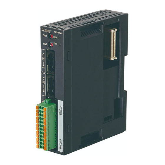
1. INTRODUCTION 1.2 Model designation (1) Rating plate The following shows an example of the rating plate for explanation of each item. AC SERVO Serial number SER. A67001001 Model MR-MT2010 IP rating, Manual number IP20 MAN.: IB(NA)0300331 Applicable power supply INPUT : 1.0A DC24V OUTPUT : 0.8A DC24V Rated output power... -
Page 14: Configuration Example Including Peripheral Equipment
1. INTRODUCTION 1.4 Configuration example including peripheral equipment POINT This section describes a combination example of extension modules. Combinations other than the example are also available. For details, refer to chapter 2. Devices other than the sensing module are optional or recommended products. The following figure shows a configuration including peripheral equipment as an example of when each MR- MT2010, MR-MT2100, MR-MT2200, MR-MT2300, and MR-MT2400 is used. - Page 15 1. INTRODUCTION MEMO 1 - 4...
-
Page 16: System Configuration
2. SYSTEM CONFIGURATION 2. SYSTEM CONFIGURATION 2.1 System configuration POINT Attach a connector cover, which is supplied with a head module, to the rightmost extension module. Attach a connector cover to a head module when the head module is used alone. For the module configuration of the sensing module, the head module must be connected at the leftmost side, and up to four extension modules can be connected at the right side of the head module. -
Page 17: Station Mode/Axis Mode
2. SYSTEM CONFIGURATION 2.2 Station mode/axis mode POINT Only when the MR-MT2200 pulse I/O module is connected to the head module, the station mode or axis mode can be selected. All other modules operate in the station mode, and the axis mode cannot be set. When the MR-MT2200 series is used, two modes are available. -
Page 18: Maximum Number Of Connections On A Network
2. SYSTEM CONFIGURATION 2.4 Maximum number of connections on a network POINT When MR-MT2200 is used in the axis mode, no restrictions are applied to the number of connectable stations because one MR-MT2200 module is handled as an axis just like servo amplifiers. 2.4.1 Station mode The following table lists the number of connectable stations of the sensing module in one SSCNET III/H system. - Page 19 2. SYSTEM CONFIGURATION Examples of how stations are counted Two head modules One head module One head module One head + Two extension modules each for one + One extension module + Four extension modules head module (four extension modules in module total) Configuration...
-
Page 20: Axis Mode (Settable Only When Mr-Mt2200 Is Connected)
2. SYSTEM CONFIGURATION 2.4.2 Axis mode (settable only when MR-MT2200 is connected) POINT When MR-MT2200 is used in the axis mode, up to four axes can be connected to one head module. Up to two axes can be connected to one MR-MT2200 module. However, when the feedback pulse input is used, only one axis can be connected to one MR- MT2200 module. -
Page 21: Compatible Servo System Controller
2. SYSTEM CONFIGURATION When the MR-MT2200 pulse I/O module is used in the axis mode, up to four axes can be connected to one head module. When feedback pulses are not inputted When feedback pulses are inputted (When two axes are connected to one MR-MT2200 (When one axis is connected to one MR-MT2200 module) module) Axis 1/... -
Page 22: Installation
3. INSTALLATION 3. INSTALLATION WARNING To prevent electric shock, ground each equipment securely. Do not connect extension modules exceeding the maximum number of connectable modules to the head module. Otherwise, the modules may malfunction. Install the sensing module on incombustible material. Installing it directly or close to combustibles will lead to a fire. - Page 23 3. INSTALLATION The following describes how to connect and remove each module of the sensing module. (1) How to connect a module Connector cover (a) Remove the connector cover of the head module. Head module's Extension module's side connector side connector Guide Coupling hook Guide...
- Page 24 3. INSTALLATION Coupling hook Connector cover (c) Make sure that the clips of the two coupling (d) Attach a connector cover to the rightmost hooks at the top and bottom are securely fit to extension module after connecting the the guides of the other module. necessary number of extension modules.
-
Page 25: How To Mount A Module
3. INSTALLATION 3.2 How to mount a module 3.2.1 Mounting a module on a DIN rail Check if the sliding hooks of the module have been securely locked on the DIN CAUTION rail. Otherwise, it may cause a malfunction and drop of the module. (1) How to mount a module on a DIN rail (Mounted) Sliding hook... - Page 26 3. INSTALLATION (2) How to remove a module from a DIN rail Wall Wall DIN rail DIN rail Sliding hook (Bottom) (a) Pull down the bottom sliding hook. (b) Pull the module toward you. Wall DIN rail (c) Lift up and remove the module. 3 - 5...
-
Page 27: Mounting A Module With Screws
3. INSTALLATION 3.2.2 Mounting a module with screws Securely pull out the sliding hooks at the top and bottom of a module until they CAUTION click. Otherwise, it may cause a malfunction and drop of the module. Screw hole Sliding hook Screw hole (1) Pull out the sliding hooks on the back of the module until they click and are fixed. -
Page 28: Installation Direction And Clearances
3. INSTALLATION 3.3 Installation direction and clearances The equipment must be installed in the specified direction. Otherwise, it may cause a malfunction. CAUTION Maintain specified clearances between the module and the inner surfaces of a control cabinet or other equipment. Otherwise, it may cause a malfunction. (1) When one block is installed Cabinet Cabinet... -
Page 29: Sscnet Iii Cable Connection
3. INSTALLATION 3.4 SSCNET III cable connection POINT Do not look directly at the light emitted from the CN1A and CN1B connectors of the MR-MT2010 and the end of the SSCNET III cable. The light can be a discomfort when it enters the eyes. (1) SSCNET III cable connection For the CN1A connector of MR-MT2010, connect the SSCNET III cable connected to a controller, a servo amplifier at the previous station, or the head module of the sensing module. - Page 30 3. INSTALLATION (2) How to connect/disconnect cables POINT The CN1A and CN1B connectors of MR-MT2010 are capped to protect light devices inside the connectors from dust. For this reason, do not remove a cap until just before connecting an SSCNET III cable. Be sure to put the cap when the SSCNET III cable is removed.
-
Page 31: How To Wire Connectors
3. INSTALLATION 3.5 How to wire connectors (1) Connecting and disconnecting cables Use the accessory connectors for wiring. Model Accessory connector MR-MT2010 DFMC-1,5/12-STF-3,5 or equivalent (Phoenix Contact) DFMC-1,5/9-STF-3,5 or equivalent (Phoenix Contact) MR-MT2100 DFMC-1,5/10-STF-3,5 or equivalent (Phoenix Contact) DFMC-1,5/12-STF-3,5 or equivalent (Phoenix Contact) MR-MT2200 DFMC-1,5/12-STF-3,5 or equivalent (Phoenix Contact) DFMC-1,5/8-STF-3,5 or equivalent (Phoenix Contact) - Page 32 3. INSTALLATION (2) Installing and removing a terminal block Use a flat head screwdriver to loosen the terminal block installation screws and remove the terminal block. Use the flat head screwdriver to tighten the terminal block installation screws and install the terminal block.
-
Page 33: Noise Reduction Techniques
3. INSTALLATION 3.6 Noise reduction techniques (1) Grounding shield of shielded cables The following shows measures against malfunctions of the sensing module when the sensing module is installed near a device which generates excessive noise. Ground a shield of the shielded cable near the sensing module, and be careful that the cable after grounding should not be affected by electromagnetic induction of the cable before grounding. - Page 34 3. INSTALLATION (2) Ferrite core A ferrite core has the effect of reducing conduction noise in the band around 10 MHz and radiated noise in the bands between 30 MHz to 100 MHz. When the shield effect of the shielded cable drawn out from the cabinet is not obtained enough or when emission of conduction noise from a power supply line should be suppressed, we recommend that you install the ferrite core.
- Page 35 3. INSTALLATION MEMO 3 - 14...
-
Page 36: Mr-Mt2010 Sscnet Iii/H Head Module
4. MR-MT2010 SSCNET III/H HEAD MODULE 4. MR-MT2010 SSCNET III/H HEAD MODULE 4.1 Summary The MR-MT2010 SSCNET III/H head module is used for SSCNET III/H communications. This module is necessary to use a sensing module. Connect extension modules to this module. This module can be used alone because it has digital I/Os. -
Page 37: Parts Identification
4. MR-MT2010 SSCNET III/H HEAD MODULE 4.4 Parts identification Detailed Name/application explanation Status display LED (RUN) Indicates the operating state of the module. Section Status display LED (ERR) Indicates that an error has occurred in the module. Station number selection rotary switch (SW1) Use this switch and SW2 to set a start station number of the sensing module. -
Page 38: Station Number Selection Rotary Switch
4. MR-MT2010 SSCNET III/H HEAD MODULE 4.5 Station number selection rotary switch POINT Cycling the control circuit power supply enables the settings of the rotary switches. Use the rotary switches (SW1 and SW2) of the MR-MT2010 SSCNET III/H head module to set a start station number. -
Page 39: Status Display Leds
4. MR-MT2010 SSCNET III/H HEAD MODULE 4.6 Status display LEDs The module status is displayed by the following two LEDs. Display LED color Status Meaning The module has been properly powered on and Flickering is waiting for a network connection. Green The module has been properly powered on and has a network connection. -
Page 40: Signals And Wiring
4. MR-MT2010 SSCNET III/H HEAD MODULE 4.7 Signals and wiring 4.7.1 Pin assignment (1) Power supply and I/O signal connector (CN2) Pin assignment of CN2 Symbol Symbol 13 1 14 2 15 3 16 4 DI10 17 5 DI11 DI12 18 6 DICOM DICOM... -
Page 41: Signal (Device) Explanations
4. MR-MT2010 SSCNET III/H HEAD MODULE 4.7.2 Signal (device) explanations (1) Input device Connector Device Symbol Function and application pin No. division CN2-13 External input signal with the timing-latch input function Input digital input signals. CN2-1 CN2-14 CN2-2 CN2-15 CN2-3 DI-1 CN2-16 CN2-4... -
Page 42: Connections Of The Power Circuit
4. MR-MT2010 SSCNET III/H HEAD MODULE 4.7.3 Connections of the power circuit MR-MT2010 24 V(+) CTL(+) 24 V power supply for interface DOCOM(-) 9, 10, or 21 (Note) Circuit protector 24 V power supply 24 V(+) for control circuit power supply Inter-module 12 or 24 connection... -
Page 43: Detailed Explanation Of Interfaces
4. MR-MT2010 SSCNET III/H HEAD MODULE 4.7.4 Detailed explanation of interfaces This section provides the details of the I/O signal interfaces (refer to the I/O division in the table) given in section 4.7.2. Refer to this section and make connection with the external device. (1) Digital input interface DI-1 (a) Sink input interface Transmit signals from sink (open-collector) type transistor output, relay switch, etc. - Page 44 4. MR-MT2010 SSCNET III/H HEAD MODULE (2) Digital output interface DO-1 (a) Sink output interface When the output FET is turned on, the current will flow to the drain terminal. Lamps, relays, or photocouplers can be driven. Install a diode (D) for an inductive load, or install an inrush current suppressing resistor (R) for a lamp load.
- Page 45 4. MR-MT2010 SSCNET III/H HEAD MODULE MEMO 4 - 10...
-
Page 46: Mr-Mt2100 I/O Module
5. MR-MT2100 I/O MODULE 5. MR-MT2100 I/O MODULE 5.1 Summary The MR-MT2100 I/O module has a highly accurate (within ± 1 µs) timing-latch input function. 5.2 Specification list Item MR-MT2100 I/O module Control circuit power supply Supplied from the head module (24 V DC ± 10%, 0.1 A) Number of input points 16 (Note 1) Insulation method... -
Page 47: Function List
5. MR-MT2100 I/O MODULE 5.3 Function list The following lists the functions of the MR-MT2100 I/O module. For details and usage of the functions, refer to the manuals for controllers. Function Description Digital input function This function sends the status of digital input signals to the controller. Digital output function This function turns on/off digital output signals using commands issued from the controller. -
Page 48: Status Display Leds
5. MR-MT2100 I/O MODULE 5.5 Status display LEDs The module status is displayed by the following two LEDs. Display LED color Status Meaning Green The module has been properly powered on. Orange Initializing The module has not been properly powered on. Flickering A warning has occurred. -
Page 49: Signal (Device) Explanations
5. MR-MT2100 I/O MODULE 5.6.2 Signal (device) explanations (1) Input device Connector Device Symbol Function and application pin No. division CN1-10 External input signal with the timing-latch input function Input digital input signals. CN1-1 CN1-11 CN1-2 CN1-12 CN1-3 CN1-13 CN1-4 DI-1 CN1-14 DI10... -
Page 50: Connecting The Interface Power Supply For Output Signal
5. MR-MT2100 I/O MODULE (3) Power supply Connector Signal name Symbol Function and application pin No. Common terminals for input signals. Input 24 V DC (24 V DC ± 10%) for I/O interface. The power supply capacity varies depending on the number of I/O CN1-9 Common terminal for interface points to be used. -
Page 51: Detailed Explanation Of Interfaces
5. MR-MT2100 I/O MODULE 5.6.4 Detailed explanation of interfaces This section provides the details of the I/O signal interfaces (refer to the I/O division in the table) given in section 5.6.2. Refer to this section and make connection with the external device. (1) Digital input interface DI-1 (a) Sink input interface Transmit signals from sink (open-collector) type transistor output, relay switch, etc. - Page 52 5. MR-MT2100 I/O MODULE (2) Digital output interface DO-1 (a) Sink output interface When the output FET is turned on, the current will flow to the drain terminal. Lamps, relays, or photocouplers can be driven. Install a diode (D) for an inductive load, or install an inrush current suppressing resistor (R) for a lamp load.
- Page 53 5. MR-MT2100 I/O MODULE (b) Source output interface When the output FET is turned on, the current will flow from the output terminal to a load. A lamp, relay, or photocoupler can be driven. Install a diode (D) for an inductive load, or install an inrush current suppressing resistor (R) for a lamp load.
-
Page 54: Mr-Mt2200 Pulse I/O Module
6. MR-MT2200 PULSE I/O MODULE 6. MR-MT2200 PULSE I/O MODULE 6.1 Summary The MR-MT2200 pulse I/O module can input/output pulses in each input/output type (forward/reverse rotation pulse train, signed pulse train, and A-phase/B-phase pulse train). The MR-MT2200 pulse I/O module has two modes: axis mode and station mode. -
Page 55: Function List
6. MR-MT2200 PULSE I/O MODULE 6.3 Function list The following table lists the functions of the MR-MT2200 pulse I/O module. For details and usage of the functions, refer to the manuals for controllers. Function Description This function outputs specified pulses from the controller. Use parameters to set an output Pulse output function type (forward/reverse rotation pulse train, signed pulse train, or A-phase/B-phase pulse train). -
Page 56: Switching The Mode Between The Station Mode And Axis Mode
6. MR-MT2200 PULSE I/O MODULE 6.5 Switching the mode between the station mode and axis mode 6.5.1 Mode select switch (SW1) POINT Cycling the control circuit power supply enables the settings of the switches. Select the axis mode or station mode for the pulse I/O module, and set input/output status for the A/B-axis in the axis mode. -
Page 57: Settings In The Station Mode
6. MR-MT2200 PULSE I/O MODULE 6.5.2 Settings in the station mode The parameter setting should match with the actual I/O connections to operate CAUTION properly. Otherwise, it may cause a malfunction. (1) I/O switching setting When the station mode is selected with SW1, set the parameters for A-axis (CN1) and B-axis (CN2) whether to input or output pulses. -
Page 58: Status Display Leds
6. MR-MT2200 PULSE I/O MODULE 6.6 Status display LEDs (1) In axis mode The module status is displayed by the following two LEDs. Display LED color Status Meaning The module has been properly powered on and Flickering A-axis is the servo-off status. Green The module has been properly powered on and A-axis is the servo-on status. -
Page 59: Signals And Wiring
6. MR-MT2200 PULSE I/O MODULE 6.7 Signals and wiring 6.7.1 Pin assignment (1) In axis mode Pin assignment of CN1 Symbol Symbol CCWA CCWGA CWGA CWNA/FANA CWPA/FAPA CCWNA/FBNA CCWPA/FBPA ALM05A DICOM05A PG05A INPA ALM24A PG24A RLSA FLSA DICOMA DOGA SONA DOCOMA RESA Pin assignment of CN2... - Page 60 6. MR-MT2200 PULSE I/O MODULE (2) In station mode Pin assignment of CN1 Symbol Symbol CCWA/DO5A CWA/DO4A CCWGA/DO5GA CWGA/DO4GA CWNA/FANA CWPA/FAPA CCWNA/FBNA CCWPA/FBPA DI105A DICOM05A DI205A DI5A DI1A DI6A DI2A DI7A DI3A DICOMA DI4A DO3A DO1A DOCOMA DO2A Pin assignment of CN2 13 1 Symbol Symbol...
-
Page 61: Signal (Device) Explanations
6. MR-MT2200 PULSE I/O MODULE 6.7.2 Signal (device) explanations (1) In axis mode (a) Input device Connector pin No. Device Symbol Function and application A-axis B-axis division FAP_ CN1-3 CN2-3 Input feedback pulses. When using feedback pulses, set the mode select switch (SW1). FAN_ CN1-15 CN2-15... - Page 62 6. MR-MT2200 PULSE I/O MODULE (b) Output device Connector pin No. Device Symbol Function and application A-axis B-axis division Outputs the command pulse. CN1-1 CN2-1 For open-collector type (max. output frequency of 500 kpulses/s) CWG_ CN1-2 CN2-2 Forward rotation pulse train between CW and CWG DO-2 Reverse rotation pulse train between CCW and CCWG CCW_...
- Page 63 6. MR-MT2200 PULSE I/O MODULE (2) In station mode (a) Input device Connector pin No. Device Symbol Function and application A-axis B-axis division FAP_ CN1-3 CN2-3 Input pulses to be counted. FAN_ CN1-15 CN2-15 Pulse input DI-1 FBP_ CN1-4 CN2-4 FBN_ CN1-16 CN2-16...
- Page 64 6. MR-MT2200 PULSE I/O MODULE (c) Power supply Connector Signal name Symbol Function and application pin No. Common terminals for input signals. When DI-2 of I/O division is used, input the I/O interface power supply. The power supply capacity varies depending on the number of I/O interface points to be used.
-
Page 65: Detailed Explanation Of Interfaces
6. MR-MT2200 PULSE I/O MODULE 6.7.3 Detailed explanation of interfaces This section provides the details of the I/O signal interfaces (refer to the I/O division in the table) given in section 6.7.2. Refer to this section and make connection with the external device. (1) Feedback pulse input interface DI-1 MR-MT2200 General-purpose pulse train driver... - Page 66 6. MR-MT2200 PULSE I/O MODULE (2) Digital (24 V/5 V) input interface DI-2 (a) Sink input interface Transmit signals from sink (open-collector) type transistor output, relay switch, etc. 1) For 5 V MR-MT2200 6.2 K ALM24_ etc. For transistor Approx. 5 mA ALM05_ etc.
- Page 67 6. MR-MT2200 PULSE I/O MODULE (b) Source input interface Transmit signals from source (open-collector) type transistor outputs, relay switches, etc. 1) For 5 V MR-MT2200 6.2 K ALM24_ etc. For transistor Approx. 5 mA ALM05_ etc. Digital input 2.2 K DICOM05_ ≤...
- Page 68 6. MR-MT2200 PULSE I/O MODULE (3) Digital (24 V) input interface DI-3 (a) Sink input interface Transmit signals from sink (open-collector) type transistor output, relay switch, etc. MR-MT2200 For transistor 6.2 K Approx. 5 mA etc. Digital input 2.2 K DICOM_ ≤...
- Page 69 6. MR-MT2200 PULSE I/O MODULE (4) Digital (24 V) output interface DO-1 (a) Sink output interface When the output transistor is turned on, the current will flow to the collector terminal. Lamps, relays, or photocouplers can be driven. Install a diode (D) for an inductive load, or install an inrush current suppressing resistor (R) for a lamp load.
- Page 70 6. MR-MT2200 PULSE I/O MODULE (b) Source output interface When the output transistor is turned on, the current will flow from the output terminal to a load. Lamps, relays, or photocouplers can be driven. Install a diode (D) for an inductive load, or install an inrush current suppressing resistor (R) for a lamp load.
- Page 71 6. MR-MT2200 PULSE I/O MODULE (5) Output interface DO-2 (a) Command pulse (open-collector) output interface General-pulse train driver 24 V MR-MT2200 2 m or less CW signal CWG_ ≤ 1.0 V CE(sat) Icmax ≤ 50 mA 24 V 100 mA (peak) MR-MT2200 CCW_ CCW signal...
- Page 72 6. MR-MT2200 PULSE I/O MODULE (b) High-speed output (DO4_/DO_5) interface 24 V MR-MT2200 2 m or less DO4_ Digital output signal DO4_ DO4G_ ≤ 1.0 V CE(sat) Icmax ≤ 50 mA 24 V 100 mA (peak) MR-MT2200 DO5_ Digital output signal DO5_ DO5G_...
- Page 73 6. MR-MT2200 PULSE I/O MODULE (6) Command pulse (differential) output interface DO-3 MR-MT2200 General-purpose pulse train driver 10 m or less CWP_ CW signal CWN_ 150 [Ω] 150 [Ω] CCWP_ CCW signal CCWN_ 150 [Ω] 150 [Ω] AM26LS31 or equivalent AM26LS32 or equivalent (Note)
-
Page 74: Command Pulse Output Form
6. MR-MT2200 PULSE I/O MODULE 6.7.4 Command pulse output form The following three different types of output pulse commands are available. Forward/reverse rotation A-phase/B-phase pulse Connection form Signal name Signed pulse train pulse train train Differential line driver CWP, CWN CW (forward rotation connection PULSE (pulse train) -
Page 75: Input Pulse Form
6. MR-MT2200 PULSE I/O MODULE 6.7.5 Input pulse form The following three different types of input pulses are available. Forward/reverse rotation A-phase/B-phase pulse Connection form Signal name Signed pulse train pulse train train CW (forward rotation FAP, FAN PULSE (pulse train) A (A-phase) pulse train) Differential line driver... -
Page 76: Mr-Mt2300 Analog I/O Module
7. MR-MT2300 ANALOG I/O MODULE 7. MR-MT2300 ANALOG I/O MODULE 7.1 Summary The MR-MT2300 analog I/O module allows analog input/output at resolution of 16 bits. 7.2 Standard specifications Item MR-MT2300 analog I/O module Control circuit power supply Supplied from the head module (24 V DC ± 10%, 0.1 A) Number of input channels Input voltage range -10 V DC to +10 V DC/-5 V DC to +5 V DC... -
Page 77: Parts Identification
7. MR-MT2300 ANALOG I/O MODULE 7.4 Parts identification Detailed Name/application explanation Status display LED (RUN) Indicates the operating status of the module. Section Status display LED (ERR) Indicates that an error has occurred in the module. Analog input signal connector (CN1) Used to connect analog input signals. -
Page 78: Status Display Leds
7. MR-MT2300 ANALOG I/O MODULE 7.5 Status display LEDs The module status is displayed by the following two LEDs. Display LED color Status Meaning Green The module has been properly powered on. Orange Initializing The module has not been properly powered on. Flickering A warning has occurred. -
Page 79: Signals And Wiring
7. MR-MT2300 ANALOG I/O MODULE 7.6 Signals and wiring POINT The analog I/O module cannot execute A/D conversion or D/A conversion unless the analog power 24 V DC is supplied. Make sure to connect the analog power supply 24 V DC. The analog output may be unstable at power-on or shut-off. -
Page 80: Signal (Device) Explanations
7. MR-MT2300 ANALOG I/O MODULE 7.6.2 Signal (device) explanations (1) Input device Connector Device Symbol Function/application pin No. division AIN1P CN1-1 Input analog signals. Analog input ch. 1 AIN1N CN1-2 Apply a voltage of -10 V DC to +10 V DC or -5 V DC to +5 V DC between AIN_P and AIN_N. -
Page 81: Description Of Interfaces
7. MR-MT2300 ANALOG I/O MODULE 7.6.3 Description of interfaces This section provides the details of the I/O signal interfaces (refer to the I/O division in the table) given in section 7.6.2. Refer to this section and make connection with the external device. (1) Analog input POINT If the circuit between terminals of unused channels remains open, an unstable... - Page 82 7. MR-MT2300 ANALOG I/O MODULE (2) Analog output MR-MT2300 10 m or less External device AOUT_P (Note 1) (Note 5) AOUT_N Shield (Note 4) (Note 2) (Note 3) (Note 2) CNP1 Note 1. Use a two-core twisted cable for wiring. 2.
- Page 83 7. MR-MT2300 ANALOG I/O MODULE MEMO 7 - 8...
-
Page 84: Mr-Mt2400 Encoder I/F Module
8. MR-MT2400 ENCODER I/F MODULE 8. MR-MT2400 ENCODER I/F MODULE 8.1 Summary The MR-MT2400 encoder I/F module sends position data received from an encoder to the servo system controller through SSCNET III/H communications. The servo system controller performs the position management and fully closed loop control by using the position data obtained through SSCNET III/H communications. -
Page 85: Parts Identification
8. MR-MT2400 ENCODER I/F MODULE 8.4 Parts identification Detailed Name/application explanation Status display LED (CH.A) Indicates the status of ch. A. Section Status display LED (CH.B) Indicates the status of ch. B. Encoder signal input connector (CN1) Section Input SSI signals. Encoder signal input connector (CN2) Inter-module connection connector (CN3B) Connect with the head module or the preceding extension module. -
Page 86: Signals And Wiring
8. MR-MT2400 ENCODER I/F MODULE 8.6 Signals and wiring 8.6.1 Pin assignment Pin assignment of CN1 Symbol Symbol CLK+_A DATA+_A CLK-_A DATA-_A CLK+_B DATA+_B CLK-_B DATA-_B Pin assignment of CN2 Symbol Symbol 8 - 3... -
Page 87: Connecting Ssi-Compatible Encoders
8. MR-MT2400 ENCODER I/F MODULE 8.6.2 Connecting SSI-compatible encoders (1) 5 V power supply specifications MR-MT2400 30 m or less Encoder CLK+_A CLK-_A DATA+_A DATA-_A (2) 24 V power supply specifications MR-MT2400 30 m or less Encoder CLK+_A CLK-_A DATA+_A DATA-_A 24 V power supply (Note) Note. -
Page 88: Parameters
9. PARAMETERS 9. PARAMETERS Never make a drastic adjustment or change to the parameter values as doing so will make the operation unstable. Do not change the parameter settings as described below. Doing so may cause an unexpected condition such as failing to start up the sensing module. Changing the values of the parameters for manufacturer setting CAUTION Setting a value outside the range... - Page 89 9. PARAMETERS (1) MR-MT2010 SSCNET III/H head module Symbol Name Initial value Unit PTA001 *HDI11 DI1 (CN2-13) setting 1 0000h PTA002 *HDI12 DI1 (CN2-13) setting 2 0000h PTA003 *HDI21 DI2 (CN2-1) setting 1 0000h PTA004 *HDI22 DI2 (CN2-1) setting 2 0000h PTA005 *HDI31...
- Page 90 9. PARAMETERS Symbol Name Initial value Unit PTA051 For manufacturer setting 0000h PTA052 0000h PTA053 0000h PTA054 0000h PTA055 0000h PTA056 0000h PTA057 0000h PTA058 0000h PTA059 0000h PTA060 0000h PTA061 0000h PTA062 0000h PTA063 0000h PTA064 0000h PTA065 0000h PTA066 0000h PTA067...
- Page 91 9. PARAMETERS Symbol Name Initial value Unit PTA106 For manufacturer setting 0000h PTA107 0000h PTA108 0000h PTA109 0000h PTA110 0000h PTA111 0000h PTA112 0000h PTA113 0000h PTA114 0000h PTA115 0000h PTA116 0000h PTA117 0000h PTA118 0000h PTA119 0000h PTA120 0000h PTA121 0000h PTA122...
- Page 92 9. PARAMETERS (2) MR-MT2100 I/O module Symbol Name Initial value Unit PTB001 *IDI11 DI1 (CN1-10) setting 1 0000h PTB002 *IDI12 DI1 (CN1-10) setting 2 0000h PTB003 *IDI21 DI2 (CN1-1) setting 1 0000h PTB004 *IDI22 DI2 (CN1-1) setting 2 0000h PTB005 *IDI31 DI3 (CN1-11) setting 1 0000h...
- Page 93 9. PARAMETERS Symbol Name Initial value Unit PTB051 *IDO81 DO8 (CN2-4) setting 1 0000h PTB052 *IDO82 DO8 (CN2-4) setting 2 0000h PTB053 *IDO91 DO9 (CN2-15) setting 1 0000h PTB054 *IDO92 DO9 (CN2-15) setting 2 0000h PTB055 *IDOA1 DO10 (CN2-5) setting 1 0000h PTB056 *IDOA2...
- Page 94 9. PARAMETERS Symbol Name Initial value Unit PTB101 ILOFL6 Level output function - Setting group 6 - Upper limit setting - Lower 0000h PTB102 ILOFH6 Level output function - Setting group 6 - Upper limit setting - Upper 0000h PTB103 *ILO7 Level output function - Setting group 7 - Detailed setting 1 0000h...
- Page 95 9. PARAMETERS Symbol Name Initial value Unit PTB151 For manufacturer setting 0000h PTB152 0000h PTB153 0000h PTB154 0000h PTB155 0000h PTB156 0000h PTB157 0000h PTB158 0000h PTB159 0000h PTB160 0000h PTB161 0000h PTB162 0000h PTB163 0000h PTB164 0000h PTB165 0000h PTB166 0000h PTB167...
- Page 96 9. PARAMETERS Symbol Name Initial value Unit PTB206 For manufacturer setting 0000h PTB207 0000h PTB208 0000h PTB209 0000h PTB210 0000h PTB211 0000h PTB212 0000h PTB213 0000h PTB214 0000h PTB215 0000h PTB216 0000h PTB217 0000h PTB218 0000h PTB219 0000h PTB220 0000h PTB221 0000h PTB222...
- Page 97 9. PARAMETERS (3) MR-MT2200 pulse I/O module Symbol Name Initial value Unit PTC001 *PFSA A-axis setting 0000h PTC002 *PIFA1 A-axis input function setting 1 0000h PTC003 *PIFA2 A-axis input function setting 2 0000h PTC004 *POFA1 A-axis output function selection 1 0000h PTC005 *POFA2...
- Page 98 9. PARAMETERS Symbol Name Initial value Unit PTC051 *IDI3B1 DI3B (CN2-7) setting 1 0000h PTC052 For manufacturer setting 0000h PTC053 *IDI4B1 DI4B (CN2-9) setting 1 0000h PTC054 For manufacturer setting 0000h PTC055 *IDI5B1 DI5B (CN2-19) setting 1 0000h PTC056 For manufacturer setting 0000h PTC057 *IDI6B1...
- Page 99 9. PARAMETERS Symbol Name Initial value Unit PTC106 For manufacturer setting 0000h PTC107 0000h PTC108 0000h PTC109 0000h PTC110 0000h PTC111 0000h PTC112 0000h PTC113 0000h PTC114 0000h PTC115 0000h PTC116 0000h PTC117 0000h PTC118 0000h PTC119 0000h PTC120 0000h PTC121 0000h PTC122...
- Page 100 9. PARAMETERS (4) MR-MT2300 analog I/O module Symbol Name Initial value Unit PTD001 *AIF1 Analog input function selection 1 0000h PTD002 *AI1F2 Analog input ch. 1 - Function selection 2 0000h PTD003 *AI1FT Analog input ch. 1 - Primary delay filter time constant [ms] PTD004 AI1OF...
- Page 101 9. PARAMETERS Symbol Name Initial value Unit PTD051 *AO3SH Analog output ch. 3 - Scaling function - Upper limit setting 20000 PTD052 *AO3SL Analog output ch. 3 - Scaling function - Lower limit setting -20000 PTD053 *AO3SF Analog output ch. 3 - Scaling function - Shift amount setting PTD054 For manufacturer setting 0000h...
- Page 102 9. PARAMETERS Symbol Name Initial value Unit PTD101 For manufacturer setting 0000h PTD102 0000h PTD103 0000h PTD104 0000h PTD105 0000h PTD106 0000h PTD107 0000h PTD108 0000h PTD109 0000h PTD110 0000h PTD111 0000h PTD112 0000h PTD113 0000h PTD114 0000h PTD115 0000h PTD116 0000h PTD117...
- Page 103 9. PARAMETERS (5) MR-MT2400 encoder I/F module Symbol Name Initial value Unit PTE001 For manufacturer setting 0003h PTE002 0000h PTE003 0000h PTE004 0000h PTE005 0000h PTE006 0000h PTE007 0000h PTE008 0000h PTE009 **ENCA Ch. A function selection 0000h PTE010 For manufacturer setting 0000h PTE011 0000h...
- Page 104 9. PARAMETERS Symbol Name Initial value Unit PTE051 For manufacturer setting 0000h PTE052 0000h PTE053 0000h PTE054 0000h PTE055 0000h PTE056 0000h PTE057 0000h PTE058 0000h PTE059 0000h PTE060 0000h PTE061 0000h PTE062 0000h PTE063 0000h PTE064 0000h PTE065 **ENCB Ch.
- Page 105 9. PARAMETERS Symbol Name Initial value Unit PTE101 For manufacturer setting 0000h PTE102 0000h PTE103 0000h PTE104 0000h PTE105 0000h PTE106 0000h PTE107 0000h PTE108 0000h PTE109 0000h PTE110 0000h PTE111 0000h PTE112 0000h PTE113 0000h PTE114 0000h PTE115 0000h PTE116 0000h PTE117...
-
Page 106: Detailed List Of Parameters
9. PARAMETERS 9.1.2 Detailed list of parameters POINT Set a value to each "x" in the "Setting digit" columns. (1) MR-MT2010 SSCNET III/H head module Initial value Setting Symbol Name and function range [Unit] PTA001 *HDI11 DI1 (CN2-13) setting 1 Refer to the Name and function column. - Page 107 9. PARAMETERS Initial value Setting Symbol Name and function range [Unit] PTA004 *HDI22 DI2 (CN2-1) setting 2 Refer to the Name and function column. Set a function for the input signal DI2 (CN2-1). Setting digit Explanation Initial value _ _ _ x Function selection Select a function for the digital input signal.
- Page 108 9. PARAMETERS Initial value Setting Symbol Name and function range [Unit] PTA008 *HDI42 DI4 (CN2-2) setting 2 Refer to the Name and function column. Set a function for the input signal DI4 (CN2-2). Setting digit Explanation Initial value _ _ _ x Function selection Select a function for the digital input signal.
- Page 109 9. PARAMETERS Initial value Setting Symbol Name and function range [Unit] PTA012 *HDI62 DI6 (CN2-3) setting 2 Refer to the Name and function column. Set a function for the input signal DI6 (CN2-3). Setting digit Explanation Initial value _ _ _ x Function selection Select a function for the digital input signal.
- Page 110 9. PARAMETERS Initial value Setting Symbol Name and function range [Unit] PTA016 *HDI82 DI8 (CN2-4) setting 2 Refer to the Name and function column. Set a function for the input signal DI8 (CN2-4). Setting digit Explanation Initial value _ _ _ x Function selection Select a function for the digital input signal.
- Page 111 9. PARAMETERS Initial value Setting Symbol Name and function range [Unit] PTA020 *HDIA2 DI10 (CN2-5) setting 2 Refer to the Name and function column. Set a function for the input signal DI10 (CN2-5). Setting digit Explanation Initial value _ _ _ x Function selection Select a function for the digital input signal.
- Page 112 9. PARAMETERS Initial value Setting Symbol Name and function range [Unit] PTA024 *HDIC2 DI12 (CN2-6) setting 2 Refer to the Name and function column. Set a function for the input signal DI12 (CN2-6). Setting digit Explanation Initial value _ _ _ x Function selection Select a function for the digital input signal.
- Page 113 9. PARAMETERS Initial value Setting Symbol Name and function range [Unit] PTA029 *HDO21 DO2 (CN2-8) setting 1 Refer to the Name and function column. Set a function for the output signal DO2 (CN2-8). Setting digit Explanation Initial value _ _ _ x Polarity selection Select a polarity for the digital output.
- Page 114 9. PARAMETERS Initial value Setting Symbol Name and function range [Unit] PTA033 *LO1 Level output function - Setting group 1 - Detailed setting 1 Refer to the Name and function column. Select a signal for the setting group 1 of the level output function. Setting digit Explanation Initial value...
- Page 115 9. PARAMETERS Initial value Setting Symbol Name and function range [Unit] PTA038 *LO2 Level output function - Setting group 2 - Detailed setting 1 Refer to the Name and function column. Select a signal for the setting group 2 of the level output function. Setting digit Explanation Initial value...
- Page 116 9. PARAMETERS (2) MR-MT2100 I/O module Initial value Setting Symbol Name and function range [Unit] PTB001 *IDI11 DI1 (CN1-10) setting 1 Refer to the Name and function column. Set a function for the input signal DI1 (CN1-10). Setting digit Explanation Initial value _ _ _ x Polarity selection...
- Page 117 9. PARAMETERS Initial value Setting Symbol Name and function range [Unit] PTB005 *IDI31 DI3 (CN1-11) setting 1 Refer to the Name and function column. Set a function for the input signal DI3 (CN1-11). Setting digit Explanation Initial value _ _ _ x Polarity selection Select a polarity for the input signal.
- Page 118 9. PARAMETERS Initial value Setting Symbol Name and function range [Unit] PTB009 *IDI51 DI5 (CN1-12) setting 1 Refer to the Name and function column. Set a function for the input signal DI5 (CN1-12). Setting digit Explanation Initial value _ _ _ x Polarity selection Select a polarity for the input signal.
- Page 119 9. PARAMETERS Initial value Setting Symbol Name and function range [Unit] PTB013 *IDI71 DI7 (CN1-13) setting 1 Refer to the Name and function column. Set a function for the input signal DI7 (CN1-13). Setting digit Explanation Initial value _ _ _ x Polarity selection Select a polarity for the input signal.
- Page 120 9. PARAMETERS Initial value Setting Symbol Name and function range [Unit] PTB017 *IDI91 DI9 (CN1-14) setting 1 Refer to the Name and function column. Set a function for the input signal DI9 (CN1-14). Setting digit Explanation Initial value _ _ _ x Polarity selection Select a polarity for the input signal.
- Page 121 9. PARAMETERS Initial value Setting Symbol Name and function range [Unit] PTB021 *IDIB1 DI11 (CN1-15) setting 1 Refer to the Name and function column. Set a function for the input signal DI11 (CN1-15). Setting digit Explanation Initial value _ _ _ x Polarity selection Select a polarity for the input signal.
- Page 122 9. PARAMETERS Initial value Setting Symbol Name and function range [Unit] PTB025 *IDID1 DI13 (CN1-16) setting 1 Refer to the Name and function column. Set a function for the input signal DI13 (CN1-16). Setting digit Explanation Initial value _ _ _ x Polarity selection Select a polarity for the input signal.
- Page 123 9. PARAMETERS Initial value Setting Symbol Name and function range [Unit] PTB029 *IDIF1 DI15 (CN1-17) setting 1 Refer to the Name and function column. Set a function for the input signal DI15 (CN1-17). Setting digit Explanation Initial value _ _ _ x Polarity selection Select a polarity for the input signal.
- Page 124 9. PARAMETERS Initial value Setting Symbol Name and function range [Unit] PTB037 *IDO11 DO1 (CN2-11) setting 1 Refer to the Name and function column. Set a function for the output signal DO1 (CN2-11). Setting digit Explanation Initial value _ _ _ x Polarity selection Select a polarity for the digital output.
- Page 125 9. PARAMETERS Initial value Setting Symbol Name and function range [Unit] PTB039 *IDO21 DO2 (CN2-1) setting 1 Refer to the Name and function column. Set a function for the output signal DO2 (CN2-1). Setting digit Explanation Initial value _ _ _ x Polarity selection Select a polarity for the digital output.
- Page 126 9. PARAMETERS Initial value Setting Symbol Name and function range [Unit] PTB041 *IDO31 DO3 (CN2-12) setting 1 Refer to the Name and function column. Set a function for the output signal DO3 (CN2-12). Setting digit Explanation Initial value _ _ _ x Polarity selection Select a polarity for the digital output.
- Page 127 9. PARAMETERS Initial value Setting Symbol Name and function range [Unit] PTB043 *IDO41 DO4 (CN2-2) setting 1 Refer to the Name and function column. Set a function for the output signal DO4 (CN2-2). Setting digit Explanation Initial value _ _ _ x Polarity selection Select a polarity for the digital output.
- Page 128 9. PARAMETERS Initial value Setting Symbol Name and function range [Unit] PTB045 *IDO51 DO5 (CN2-13) setting 1 Refer to the Name and function column. Set a function for the output signal DO5 (CN2-13). Setting digit Explanation Initial value _ _ _ x Polarity selection Select a polarity for the digital output.
- Page 129 9. PARAMETERS Initial value Setting Symbol Name and function range [Unit] PTB047 *IDO61 DO6 (CN2-3) setting 1 Refer to the Name and function column. Set a function for the output signal DO6 (CN2-3). Setting digit Explanation Initial value _ _ _ x Polarity selection Select a polarity for the digital output.
- Page 130 9. PARAMETERS Initial value Setting Symbol Name and function range [Unit] PTB049 *IDO71 DO7 (CN2-14) setting 1 Refer to the Name and function column. Set a function for the output signal DO7 (CN2-14). Setting digit Explanation Initial value _ _ _ x Polarity selection Select a polarity for the digital output.
- Page 131 9. PARAMETERS Initial value Setting Symbol Name and function range [Unit] PTB051 *IDO81 DO8 (CN2-4) setting 1 Refer to the Name and function column. Set a function for the output signal DO8 (CN2-4). Setting digit Explanation Initial value _ _ _ x Polarity selection Select a polarity for the digital output.
- Page 132 9. PARAMETERS Initial value Setting Symbol Name and function range [Unit] PTB053 *IDO91 DO9 (CN2-15) setting 1 Refer to the Name and function column. Set a function for the output signal DO9 (CN2-15). Setting digit Explanation Initial value _ _ _ x Polarity selection Select a polarity for the digital output.
- Page 133 9. PARAMETERS Initial value Setting Symbol Name and function range [Unit] PTB055 *IDOA1 DO10 (CN2-5) setting 1 Refer to the Name and function column. Set a function for the output signal DO10 (CN2-5). Setting digit Explanation Initial value _ _ _ x Polarity selection Select a polarity for the digital output.
- Page 134 9. PARAMETERS Initial value Setting Symbol Name and function range [Unit] PTB057 *IDOB1 DO11 (CN2-16) setting 1 Refer to the Name and function column. Set a function for the output signal DO11 (CN2-16). Setting digit Explanation Initial value _ _ _ x Polarity selection Select a polarity for the digital output.
- Page 135 9. PARAMETERS Initial value Setting Symbol Name and function range [Unit] PTB059 *IDOC1 DO12 (CN2-6) setting 1 Refer to the Name and function column. Set a function for the output signal DO12 (CN2-6). Setting digit Explanation Initial value _ _ _ x Polarity selection Select a polarity for the digital output.
- Page 136 9. PARAMETERS Initial value Setting Symbol Name and function range [Unit] PTB061 *IDOD1 DO13 (CN2-17) setting 1 Refer to the Name and function column. Set a function for the output signal DO13 (CN2-17). Setting digit Explanation Initial value _ _ _ x Polarity selection Select a polarity for the digital output.
- Page 137 9. PARAMETERS Initial value Setting Symbol Name and function range [Unit] PTB063 *IDOE1 DO14 (CN2-7) setting 1 Refer to the Name and function column. Set a function for the output signal DO14 (CN2-7). Setting digit Explanation Initial value _ _ _ x Polarity selection Select a polarity for the digital output.
- Page 138 9. PARAMETERS Initial value Setting Symbol Name and function range [Unit] PTB065 *IDOF1 DO15 (CN2-18) setting 1 Refer to the Name and function column. Set a function for the output signal DO15 (CN2-18). Setting digit Explanation Initial value _ _ _ x Polarity selection Select a polarity for the digital output.
- Page 139 9. PARAMETERS Initial value Setting Symbol Name and function range [Unit] PTB067 *IDOG1 DO16 (CN2-8) setting 1 Refer to the Name and function column. Set a function for the output signal DO16 (CN2-8). Setting digit Explanation Initial value _ _ _ x Polarity selection Select a polarity for the digital output.
- Page 140 9. PARAMETERS Initial value Setting Symbol Name and function range [Unit] PTB073 *ILO1 Level output function - Setting group 1 - Detailed setting 1 Refer to the Name and function column. Select a signal for the setting group 1 of the level output function. Setting digit Explanation Initial value...
- Page 141 9. PARAMETERS Initial value Setting Symbol Name and function range [Unit] PTB078 *ILO2 Level output function - Setting group 2 - Detailed setting 1 Refer to the Name and function column. Select a signal for the setting group 2 of the level output function. Setting digit Explanation Initial value...
- Page 142 9. PARAMETERS Initial value Setting Symbol Name and function range [Unit] PTB084 ILONL3 Level output function - Setting group 3 - Lower limit setting - Lower 0000h 0000h Set the lower digits for the lower limit with the level output function. Set with 32-bit signed hexadecimal values by combining upper [Pr.
- Page 143 9. PARAMETERS Initial value Setting Symbol Name and function range [Unit] PTB093 *ILO5 Level output function - Setting group 5 - Detailed setting 1 Refer to the Name and function column. Select a signal for the setting group 5 of the level output function. Setting digit Explanation Initial value...
- Page 144 9. PARAMETERS Initial value Setting Symbol Name and function range [Unit] PTB099 ILONL6 Level output function - Setting group 6 - Lower limit setting - Lower 0000h 0000h Set the lower digits for the lower limit with the level output function. Set with 32-bit signed hexadecimal values by combining upper [Pr.
- Page 145 9. PARAMETERS Initial value Setting Symbol Name and function range [Unit] PTB108 *ILO8 Level output function - Setting group 8 - Detailed setting 1 Refer to the Name and function column. Select a signal for the setting group 8 of the level output function. Setting digit Explanation Initial value...
- Page 146 9. PARAMETERS (3) MR-MT2200 pulse I/O module Initial value Setting Symbol Name and function range [Unit] PTC001 *PFSA A-axis setting Refer to the Name and function column. Select an I/O function for A-axis of the pulse I/O module. Setting digit Explanation Initial value _ _ _ x...
- Page 147 9. PARAMETERS Initial value Setting Symbol Name and function range [Unit] PTC004 *POFA1 A-axis output function selection 1 Refer to the Name and function column. Set for A-axis of the pulse I/O module when the pulse output function is used. Setting digit Explanation Initial value...
- Page 148 9. PARAMETERS Initial value Setting Symbol Name and function range [Unit] PTC008 *CDVA A-axis output-side electronic gear setting Refer to the Name and function column. Set an electronic gear when the pulse output function is selected. The electronic gear is applied for the output command pulses from the controller. Setting digit Explanation Initial value...
- Page 149 9. PARAMETERS Initial value Setting Symbol Name and function range [Unit] PTC019 *PIFB2 B-axis input function setting 2 Refer to the Name and function column. Select a filter for the input pulses of B-axis of the pulse I/O module. Setting digit Explanation Initial value _ _ _ x...
- Page 150 9. PARAMETERS Initial value Setting Symbol Name and function range [Unit] PTC021 *POFB2 B-axis output function selection 2 Refer to the Name and function column. Set for B-axis of the pulse I/O module when the output function is used. Setting digit Explanation Initial value _ _ _ x...
- Page 151 9. PARAMETERS Initial value Setting Symbol Name and function range [Unit] PTC035 *IDI2A1 DI2A (CN1-10) setting 1 Refer to the Name and function column. Set a function for the input signal DI2A (CN1-10). Setting digit Explanation Initial value _ _ _ x Polarity selection Select a polarity for the input signal.
- Page 152 9. PARAMETERS Initial value Setting Symbol Name and function range [Unit] PTC043 *IDI6A1 DI6A (CN1-20) setting 1 Refer to the Name and function column. Set a function for the input signal DI6A (CN1-20). Setting digit Explanation Initial value _ _ _ x Polarity selection Select a polarity for the input signal.
- Page 153 9. PARAMETERS Initial value Setting Symbol Name and function range [Unit] PTC051 *IDI3B1 DI3B (CN2-7) setting 1 Refer to the Name and function column. Set a function for the input signal DI3B (CN2-7). Setting digit Explanation Initial value _ _ _ x Polarity selection Select a polarity for the input signal.
- Page 154 9. PARAMETERS Initial value Setting Symbol Name and function range [Unit] PTC059 *IDI7B1 DI7B (CN2-21) setting 1 Refer to the Name and function column. Set a function for the input signal DI7B (CN2-21). Setting digit Explanation Initial value _ _ _ x Polarity selection Select a polarity for the input signal.
- Page 155 9. PARAMETERS Initial value Setting Symbol Name and function range [Unit] PTC067 *IDO2A1 DO2A (CN1-12) setting 1 Refer to the Name and function column. Set a function for the output signal DO2A (CN1-12). Setting digit Explanation Initial value _ _ _ x Polarity selection Select a polarity for the digital output.
- Page 156 9. PARAMETERS Initial value Setting Symbol Name and function range [Unit] PTC069 *IDO3A1 DO3A (CN1-23) setting 1 Refer to the Name and function column. Set a function for the output signal DO3A (CN1-23). Setting digit Explanation Initial value _ _ _ x Polarity selection Select a polarity for the digital output.
- Page 157 9. PARAMETERS Initial value Setting Symbol Name and function range [Unit] PTC071 *IDO4A1 DO4A (CN1-1) setting 1 Refer to the Name and function column. Set a function for the output signal DO4A (CN1-1). Setting digit Explanation Initial value _ _ _ x Polarity selection Select a polarity for the digital output.
- Page 158 9. PARAMETERS Initial value Setting Symbol Name and function range [Unit] PTC073 *IDO5A1 DO5A (CN1-13) setting 1 Refer to the Name and function column. Set a function for the output signal DO5A (CN1-13). Setting digit Explanation Initial value _ _ _ x Polarity selection Select a polarity for the digital output.
- Page 159 9. PARAMETERS Initial value Setting Symbol Name and function range [Unit] PTC075 *IDO1B1 DO1B (CN2-11) setting 1 Refer to the Name and function column. Set a function for the output signal DO1B (CN2-11). Setting digit Explanation Initial value _ _ _ x Polarity selection Select a polarity for the digital output.
- Page 160 9. PARAMETERS Initial value Setting Symbol Name and function range [Unit] PTC077 *IDO2B1 DO2B (CN2-12) setting 1 Refer to the Name and function column. Set a function for the output signal DO2B (CN2-12). Setting digit Explanation Initial value _ _ _ x Polarity selection Select a polarity for the digital output.
- Page 161 9. PARAMETERS Initial value Setting Symbol Name and function range [Unit] PTC079 *IDO3B1 DO3B (CN2-23) setting 1 Refer to the Name and function column. Set a function for the output signal DO3B (CN2-23). Setting digit Explanation Initial value _ _ _ x Polarity selection Select a polarity for the digital output.
- Page 162 9. PARAMETERS Initial value Setting Symbol Name and function range [Unit] PTC081 *IDO4B1 DO4B (CN2-1) setting 1 Refer to the Name and function column. Set a function for the output signal DO4B (CN2-1). Setting digit Explanation Initial value _ _ _ x Polarity selection Select a polarity for the digital output.
- Page 163 9. PARAMETERS Initial value Setting Symbol Name and function range [Unit] PTC083 *IDO5B1 DO5B (CN2-1) setting 1 Refer to the Name and function column. Set a function for the output signal DO5B (CN2-13). Setting digit Explanation Initial value _ _ _ x Polarity selection Select a polarity for the digital output.
- Page 164 9. PARAMETERS (4) MR-MT2300 analog I/O module Initial value Setting Symbol Name and function range [Unit] PTD001 *AIF1 Analog input function selection 1 Refer to the Name and function column. Set a function of analog input. Setting digit Explanation Initial value _ _ _ x Analog input sampling cycle Select an analog input sampling cycle.
- Page 165 9. PARAMETERS Initial value Setting Symbol Name and function range [Unit] PTD003 *AI1FT Analog input ch. 1 - Primary delay filter time constant Refer to the Name Set a primary delay filter time constant of analog input ch. 1. [ms] This parameter will be enabled when "Primary delay filter (_ _ _ 3)"...
- Page 166 9. PARAMETERS Initial value Setting Symbol Name and function range [Unit] PTD011 *AI2FT Analog input ch. 2 - Primary delay filter time constant Refer to the Name Set a primary delay filter time constant of analog input ch. 2. [ms] This parameter will be enabled when "Primary delay filter (_ _ _ 3)"...
- Page 167 9. PARAMETERS Initial value Setting Symbol Name and function range [Unit] PTD019 *AI3FT Analog input ch. 3 - Primary delay filter time constant Refer to the Name Set a primary delay filter time constant of analog input ch. 3. [ms] This parameter will be enabled when "Primary delay filter (_ _ _ 3)"...
- Page 168 9. PARAMETERS Initial value Setting Symbol Name and function range [Unit] PTD027 *AI4FT Analog input ch. 4 - Primary delay filter time constant Refer to the Name Set a primary delay filter time constant of analog input ch. 4. [ms] This parameter will be enabled when "Primary delay filter (_ _ _ 3)"...
- Page 169 9. PARAMETERS Initial value Setting Symbol Name and function range [Unit] PTD042 AO2OF Analog output ch. 2 - Offset -10000 Set the offset of analog output ch. 2. [mV] [AL. 37 Parameter error] may occur depending on the setting combination of [Pr. 10000 PTD042] to [Pr.
- Page 170 9. PARAMETERS Initial value Setting Symbol Name and function range [Unit] PTD060 *AO4SL Analog output ch. 4 - Scaling function - Lower limit setting -20000 -32768 Set the internal value when -10 V is inputted. [AL. 37 Parameter error] may occur depending on the setting combination of [Pr. 32767 PTD058] to [Pr.
- Page 171 9. PARAMETERS Initial value Setting Symbol Name and function range [Unit] PTD072 *AIAV2C2 Analog input average 2 - Ch. 2 weighting Set the weighting for channel 2. 10000 PTD073 *AIAV2C3 Analog input average 2 - Ch. 3 weighting Set the weighting for channel 3. 10000 PTD074 *AIAV2C4 Analog input average 2 - Ch.
- Page 172 9. PARAMETERS (5) MR-MT2400 encoder I/F module Initial value Setting Symbol Name and function range [Unit] PTE009 **ENCA Ch. A function selection Refer to the Name and function column. Select enable/disable and a polarity for Ch. A function. Setting digit Explanation Initial value _ _ _ x...
- Page 173 9. PARAMETERS Initial value Setting Symbol Name and function range [Unit] PTE038 **SECA2 SSI - Ch. A function setting 2 Refer to the Name and function column. Set basic information of ch. A encoder when SSI is selected. Setting digit Explanation Initial value _ _ x x...
- Page 174 9. PARAMETERS Initial value Setting Symbol Name and function range [Unit] PTE042 **SECA6 SSI - Ch. A function setting 6 Refer to the Name and function column. Set the error check method of ch. A when SSI is selected. Setting digit Explanation Initial value _ _ _ x...
- Page 175 9. PARAMETERS Initial value Setting Symbol Name and function range [Unit] PTE065 **ENCB Ch. B function selection Refer to the Name and function column. Select enable/disable and a polarity for Ch. B function. Setting digit Explanation Initial value _ _ _ x Polarity selection Select a polarity of the encoder.
- Page 176 9. PARAMETERS Initial value Setting Symbol Name and function range [Unit] PTE094 **SECB2 SSI - Ch. B function setting 2 Refer to the Name and function column. Set basic information of ch. B encoder when SSI is selected. Setting digit Explanation Initial value _ _ x x...
- Page 177 9. PARAMETERS Initial value Setting Symbol Name and function range [Unit] PTE098 **SECB6 SSI - Ch. B function setting 6 Refer to the Name and function column. Set the error check method of ch. B when SSI is selected. Setting digit Explanation Initial value _ _ _ x...
-
Page 178: Axis Mode
9. PARAMETERS 9.2 Axis mode 9.2.1 Parameter list POINT The parameter whose symbol is preceded by * is enabled with the following conditions: *: After setting the parameter, cycle the power or reset the controller. **: After setting the parameter, cycle the power. (1) Basic setting parameters ([Pr. - Page 179 9. PARAMETERS (2) Gain/filter setting parameters ([Pr. PB_ _ ]) Symbol Name Initial value Unit PB01 *DEL [AL. 35 I/O pulse frequency error] alarm level selection 0000h PB02 For manufacturer setting 0000h PB03 PB04 PB05 PB06 PB07 PB08 PB09 *TOP Motor maximum speed 6000 r/min...
- Page 180 9. PARAMETERS Symbol Name Initial value Unit PB51 For manufacturer setting 0000h PB52 0000h PB53 0000h PB54 0000h PB55 0000h PB56 0000h PB57 0000h PB58 0000h PB59 0000h PB60 0000h PB61 0000h PB62 0000h PB63 0000h PB64 0000h 9 - 93...
- Page 181 9. PARAMETERS (3) Extension setting parameters ([Pr. PC_ _ ]) Symbol Name Initial value Unit PC01 For manufacturer setting PC02 PC03 0000h PC04 0000h PC05 0000h PC06 0000h PC07 PC08 PC09 0000h PC10 0000h PC11 PC12 PC13 PC14 PC15 PC16 0000h PC17 0000h...
- Page 182 9. PARAMETERS Symbol Name Initial value Unit PC50 For manufacturer setting 0000h PC51 0000h PC52 0000h PC53 0000h PC54 0000h PC55 0000h PC56 0000h PC57 0000h PC58 0000h PC59 0000h PC60 0000h PC61 0000h PC62 0000h PC63 0000h PC64 0000h 9 - 95...
-
Page 183: Detailed List Of Parameters
9. PARAMETERS 9.2.2 Detailed list of parameters POINT Set a value to each "x" in the "Setting digit" columns. (1) Basic setting parameters ([Pr. PA_ _ ]) Initial value Setting Symbol Name and function range [Unit] PA06 *EGM Output-side electronic gear multiplication Set an electronic gear multiplication for the output side. - Page 184 9. PARAMETERS Initial value Setting Symbol Name and function range [Unit] PA15 *PRL Number of pulses per revolution setting Lower 4000 [pulse/rev] Set the number of command pulses per motor revolution. Set the lower four digits of the number of pulses per revolution in decimal numbers 9999 in this parameter.
- Page 185 9. PARAMETERS Initial value Setting Symbol Name and function range [Unit] PA18 *DOL Output signal logic selection Refer to the Name and function column. Select a logic for the output signal. Setting digit Explanation Initial value _ _ _ x _ _ _ x Bit 0: SON (Servo-on) 0: Negative logic...
- Page 186 9. PARAMETERS Initial value Setting Symbol Name and function range [Unit] PB11 Virtual RD signal delay time [ms] Set the delay time until the virtual RD signal turns on after the servo-on output turns on. 1000 PB12 Clear signal output pulse width time Set the minimum time for the clear output to be on.
- Page 187 9. PARAMETERS Initial value Setting Symbol Name and function range [Unit] PB16 *IOP Input function selection Refer to the Name and function column. Select an input function. Setting digit Explanation Initial value _ _ _ x ALM (Malfunction) input setting 0: Disable the alarm detection 1: Enable the alarm detection _ _ x _...
- Page 188 9. PARAMETERS Initial value Setting Symbol Name and function range [Unit] PB18 *BAS Motor rated speed 3000 Set the rated speed of the motor to be used. [r/min] When the rated speed of the motor is unknown, set a value equal to or less than 10000 [Pr.
- Page 189 9. PARAMETERS (3) Extension setting parameters ([Pr. PC_ _ ]) Initial value Setting Symbol Name and function range [Unit] PC33 *HDI1 Head module DI1 (CN2-13) setting Refer to the Name and function column. Set a function for the head module input signal DI1 (CN2-13). This parameter is enabled only for the first axis of one block.
- Page 190 9. PARAMETERS Initial value Setting Symbol Name and function range [Unit] PC37 *HDI5 Head module DI5 (CN2-15) setting Refer to the Name and function column. Set a function for the head module input signal DI5 (CN2-15). This parameter is enabled only for the first axis of one block. The setting is not valid for the other axes.
- Page 191 9. PARAMETERS Initial value Setting Symbol Name and function range [Unit] PC41 *HDI9 Head module DI9 (CN2-17) setting Refer to the Name and function column. Set a function for the head module input signal DI9 (CN2-17). This parameter is enabled only for the first axis of one block. The setting is not valid for the other axes.
- Page 192 9. PARAMETERS Initial value Setting Symbol Name and function range [Unit] PC47 *HDO1 Head module DO1 (CN2-20) setting Refer to the Name and function column. Set a function for the head module output signal DO1 (CN2-20). This parameter is enabled only for the first axis of one block. The setting is not valid for the other axes.
- Page 193 9. PARAMETERS MEMO 9 - 106...
-
Page 194: Troubleshooting
10. TROUBLESHOOTING 10. TROUBLESHOOTING POINT An alarm No. will not be shown on the module LED. Check the alarm No. of the sensing module by starting MELSOFT MR Configurator2 via MELSOFT MT Works2. [AL. 37 Parameter error] and warnings are not recorded in the alarm history. The symbols in the target column mean as follows. -
Page 195: Alarm List
10. TROUBLESHOOTING 10.2 Alarm list Alarm deactivation Target module Detail Stop Cycling Name Detail name Alarm method reset reset MT2010 MT2100 MT2200 MT2300 MT2400 power Voltage drop in the control 10.1 circuit power modules Head module 10.3 Voltage drop in the external modules Undervoltage input power supply... - Page 196 10. TROUBLESHOOTING Alarm deactivation Target module Detail Stop Cycling Name Detail name Alarm method reset reset MT2010 MT2100 MT2200 MT2300 MT2400 power Encoder I/F module - Ch. A 20.1 Normal communication - Each unit Receive data error 1 Encoder I/F module - Ch. A 20.2 Normal communication - Each unit...
- Page 197 10. TROUBLESHOOTING Alarm deactivation Target module Detail Stop Cycling Name Detail name Alarm method reset reset MT2010 MT2100 MT2200 MT2300 MT2400 power Pulse I/O module - Ch. A 35.1 Each unit Output pulse frequency error Pulse I/O module - Ch. B 35.2 Each unit I/O pulse...
-
Page 198: Warning List
10. TROUBLESHOOTING Alarm deactivation Target module Detail Stop Cycling Name Detail name Alarm method MT2010 MT2100 MT2200 MT2300 MT2400 reset reset power Serial communication 8E.4 Serial command error modules communication Serial communication data error 8E.5 number error modules Watchdog Watchdog (Note 2) (Note 2) modules... -
Page 199: Remedies For Alarms
10. TROUBLESHOOTING 10.4 Remedies for alarms When an alarm occurs, eliminate its cause, ensure safety, and deactivate the CAUTION alarm to restart operation. Otherwise, it may cause injury. POINT [AL. 37 Parameter error] is not recorded in the alarm history. The alarm No. - Page 200 10. TROUBLESHOOTING Alarm No.: 10 Name: Undervoltage The voltage of the control circuit power supply has dropped. Alarm content The voltage in the external input power supply has dropped. Detail Detail name Cause Check method Check result Action Target 10.4 Voltage drop in (1) Connection error is Check the connection...
- Page 201 10. TROUBLESHOOTING Alarm No.: 12 Name: Memory error 1 (RAM) Alarm content A part (RAM) in the head module failed. Detail Detail name Cause Check method Check result Action Target 12.1 RAM error 1 (1) A part in the head Disconnect the cables It is repeatable.
- Page 202 10. TROUBLESHOOTING Alarm No.: 14 Name: Control process error Alarm content The process did not complete within the specified time. Detail Detail name Cause Check method Check result Action Target 14.1 Control (1) The parameter setting is Check if the parameter It is incorrect.
- Page 203 10. TROUBLESHOOTING Alarm No.: 15 Name: Memory error 2 (EEP-ROM) Alarm content A part (EEP-ROM) in the head module failed. Detail Detail name Cause Check method Check result Action Target 15.1 EEP-ROM error (1) EEP-ROM is Disconnect the cables It is repeatable. Replace the head [MT2010] at power on...
- Page 204 10. TROUBLESHOOTING Alarm No.: 19 Name: Memory error 3 (Flash-ROM) Alarm content A part (Flash-ROM) in the head module failed. Detail Detail name Cause Check method Check result Action Target 19.1 Flash-ROM (1) The Flash-ROM is Disconnect the cables It is repeatable. Replace the head [MT2010] error 1...
- Page 205 10. TROUBLESHOOTING Alarm No.: 1E Name: Encoder I/F module - Initial communication error 2 Alarm content The encoder connected to the encoder I/F module is malfunctioning. Detail Detail name Cause Check method Check result Action Target 1E.1 Encoder I/F (1) The encoder connected Replace the encoder It is not repeatable.
- Page 206 10. TROUBLESHOOTING Alarm No.: 20 Name: Encoder I/F module - Ch. A Normal communication error 1 Alarm content A communication error has occurred between the encoder connected to ch. A and the encoder I/F module. Detail Detail name Cause Check method Check result Action Target...
- Page 207 10. TROUBLESHOOTING Alarm No.: 20 Name: Encoder I/F module - Ch. A Normal communication error 1 Alarm content A communication error has occurred between the encoder connected to ch. A and the encoder I/F module. Detail Detail name Cause Check method Check result Action Target...
- Page 208 10. TROUBLESHOOTING Alarm No.: 21 Name: Encoder I/F module - Ch. A Normal communication error 2 Alarm content The encoder connected to ch. A detected an error signal. Detail Detail name Cause Check method Check result Action Target 21.1 Encoder I/F (1) The external conductor Check if it is Not connected...
- Page 209 10. TROUBLESHOOTING Alarm No.: 28 Name: Encoder I/F module - Linear encoder error 2 Alarm content The working environment of the encoder connected to the encoder I/F module is not normal. Detail Detail name Cause Check method Check result Action Target 28.1 Encoder I/F...
- Page 210 10. TROUBLESHOOTING Alarm No.: 2A Name: Encoder I/F module - Ch. A Linear encoder error 1 An error was detected in the linear encoder connected to ch. A of the encoder I/F module. (The details Alarm content vary depending on the linear encoder manufacturer.) Detail Detail name Cause...
- Page 211 10. TROUBLESHOOTING Alarm No.: 34 Name: SSCNET receive error 1 Alarm content An error occurred in SSCNET III/H communications. (continuous communication error with 3.5 ms interval) Detail Detail name Cause Check method Check result Action Target 34.2 SSCNET Check it with the check method for [AL. 34.1]. connector connection error 34.3...
- Page 212 10. TROUBLESHOOTING Alarm No.: 35 Name: I/O pulse frequency error The pulse frequency to be input to the pulse I/O module is too high. Alarm content The pulse frequency to be output from the pulse I/O module is too high. Detail Detail name Cause...
- Page 213 10. TROUBLESHOOTING Alarm No.: 36 Name: SSCNET receive error 2 An error occurred in SSCNET III/H communications. (intermittent communication error with about 70 ms Alarm content interval) Detail Detail name Cause Check method Check result Action Target 36.1 Continuous (1) The SSCNET III cable Check the SSCNET III Disconnected Turn off the control...
- Page 214 10. TROUBLESHOOTING Alarm No.: 37 Name: Parameter error Alarm content The parameter setting is incorrect. Detail Detail name Cause Check method Check result Action Target 37.1 Parameter (1) A parameter was set out Check the parameter It is out of setting Set it within the [MT2010] setting range...
- Page 215 10. TROUBLESHOOTING Alarm No.: 71 Name: Encoder I/F module - Ch. B Initial communication error 1 Alarm content A communication error has occurred between the encoder connected to ch. B and the encoder I/F module. Detail Detail name Cause Check method Check result Action Target...
- Page 216 10. TROUBLESHOOTING Alarm No.: 71 Name: Encoder I/F module - Ch. B Initial communication error 1 Alarm content A communication error has occurred between the encoder connected to ch. B and the encoder I/F module. Detail Detail name Cause Check method Check result Action Target...
- Page 217 10. TROUBLESHOOTING Alarm No.: 72 Name: Encoder I/F module - Ch. B Normal communication error 2 Alarm content The encoder connected to ch. B detected an error signal. Detail Detail name Cause Check method Check result Action Target 72.1 Encoder I/F (1) The external conductor Check if it is Not connected...
- Page 218 10. TROUBLESHOOTING Alarm No.: 75 Name: Extension module error Alarm content An extension module is malfunctioning. Detail Detail name Cause Check method Check result Action Target 75.1 Reset signal (1) A module is Replace the It is not repeatable. Replace the module. [MT2100] error malfunctioning.
- Page 219 10. TROUBLESHOOTING Alarm No.: 76 Name: Encoder I/F module - Ch. B Linear encoder error 1 An error was detected in the linear encoder connected to ch. B of the encoder I/F module. (The details Alarm content vary depending on the linear encoder manufacturer.) Detail Detail name Cause...
- Page 220 10. TROUBLESHOOTING Alarm No.: 8E Name: Serial communication error A communication error occurred between the head module and controller. Alarm content An error occurred in the serial communication (Mitsubishi Electric general-purpose AC servo protocol). Detail Detail name Cause Check method...
-
Page 221: Remedies For Warnings
10. TROUBLESHOOTING 10.5 Remedies for warnings An operation will be stopped with [AL. E7]. If any other warning occurs, the operation can be continued, but an alarm may occur, causing improper operation. A warning No. will not be shown on the module LED. Check the warning No. of the sensing module by starting MELSOFT MR Configurator2 via MELSOFT MT Works2. -
Page 222: Trouble Which Does Not Trigger An Alarm/Warning
10. TROUBLESHOOTING 10.6 Trouble which does not trigger an alarm/warning POINT When the sensing module malfunctions, the following status may occur. The following shows some examples of possible causes which do not trigger an alarm or warning. Remove each cause by referring to this section. 10.6.1 MR-MT2010 SSCNET III/H head module LED display status Possible cause... -
Page 223: Mr-Mt2200 Pulse I/O Module
10. TROUBLESHOOTING 10.6.3 MR-MT2200 pulse I/O module LED display status Possible cause Check result Action AX.A AX.B On in red On in red An alarm has occurred in A- Check if an alarm has Take actions following the remedies for axis or B-axis. -
Page 224: Mr-Mt2400 Encoder I/F Module
10. TROUBLESHOOTING 10.6.5 MR-MT2400 encoder I/F module LED display status Possible cause Check result Action CH.A CH.B On in red On in red An alarm has occurred in A- Check if an alarm has Take actions following the remedies for axis or B-axis. - Page 225 10. TROUBLESHOOTING MEMO 10 - 32...
-
Page 226: Dimensions
11. DIMENSIONS 11. DIMENSIONS (1) MR-MT2010 [Unit: mm] 29.1 2-φ5 14.55 Mounting screw Screw size: M4 Tightening torque: 1.24 [N•m] 2 screws for fixing connector Tightening torque: 0.1 [N•m] to 0.2 [N•m] Mass: 0.2 [kg] (2) MR-MT2100 [Unit: mm] 29.1 2-φ5 14.55 Mounting screw... - Page 227 11. DIMENSIONS (3) MR-MT2200 [Unit: mm] 29.1 2-φ5 14.55 Mounting screw Screw size: M4 Tightening torque: 1.24 [N•m] 4 screws for fixing connectors Tightening torque: 0.1 [N•m] to 0.2 [N•m] Mass: 0.2 [kg] (4) MR-MT2300 [Unit: mm] 29.1 2-φ5 14.55 Mounting screw Screw size: M4 Tightening torque: 1.24 [N•m]...
- Page 228 11. DIMENSIONS (5) MR-MT2400 [Unit: mm] 29.1 2-φ5 14.55 Mounting screw Screw size: M4 Tightening torque: 1.24 [N•m] 4 screws for fixing connectors Tightening torque: 0.1 [N•m] to 0.2 [N•m] Mass: 0.2 [kg] 11 - 3...
- Page 229 11. DIMENSIONS MEMO 11 - 4...
-
Page 230: Appendix
Use the sensing modules within specifications. Refer to section 1.3, 4.2, 5.2, 6.2, 7.2 and 8.2 for specifications such as voltage, temperature, etc. Mitsubishi Electric Co. accepts no claims for liability if the equipment is used in any other way or if modifications are made to the device, even in the context of mounting and installation. - Page 231 DC power supply. (b) For Declaration of Conformity (DoC) Hereby, MITSUBISHI ELECTRIC EUROPE B.V., declares that the sensing modules are in compliance with the necessary requirements and standards (2014/30/EU). For the copy of Declaration of Conformity, contact your local sales office.
- Page 232 APPENDIX (4) South Korea compliance This product complies with the Radio Wave Law (KC mark). Please note the following to use the product. 이 기기는 업무용 (A급) 전자파적합기기로서 판매자 또는 사용자는 이 점을 주의하시기 바라며, 가정외의 지역에서 사용하는 것을 목적으로 합니다. (The product is for business use (Class A) and meets the electromagnetic compatibility requirements.
- Page 233 APPENDIX App. 1.1.5 Residual risk (1) Only qualified personnel are authorized to install, start-up, repair or service the machines in which these components are installed. Only trained engineers should install and operate the equipment. (ISO 13849- 1 Table F.1 No. 5) (2) Protect the cables with appropriate ways (routing them in a cabinet, using a cable guard, etc.).
- Page 234 APPENDIX App. 1.3 Configuration diagram Securely connect the cables in the specified method. Otherwise, the servo motor CAUTION may operate unexpectedly. The following shows configuration examples of sensing modules. Sensing modules are connected to the servo system controller by SSCNET III/H communication. Sensing modules can be connected to the same network system with the SSCNET III/H interface servo amplifier.
- Page 235 APPENDIX App. 1.4 Signals The following shows MR-MT2010 signals as a typical example. App. 1.4.1 Signal Pin No. Symbol Symbol Pin No. DI10 DI11 DI12 DICOM DICOM DOCOM(-) DOCOM(-) CTL(+) DOCOM(-) 13 1 24 V(+) 14 2 15 3 16 4 17 5 18 6 19 7...
- Page 236 APPENDIX App. 1.4.2 I/O device Symbol Device Connector Pin No. DI1 to DI12 Digital input 1 to 6/13 to 18 DO1/DO2 Digital output 8/20 DICOM Common terminal for input signals 7/19 DOCOM(-) Common terminal for output signals 9/10/21 24 V(+)/24G Control circuit power supply 11/23 Grounding...
- Page 237 APPENDIX App. 1.6 Transportation and storage Transport the products correctly according to their mass. Stacking in excess of the limited number of product packages is not allowed. CAUTION Install the product in a load-bearing place of sensing module in accordance with the instruction manual.
- Page 238 APPENDIX App. 1.7 Technical data App. 1.7.1 MR-MT2010 Item Specifications Voltage 24 V DC Control circuit power Permissible voltage 24 V DC ± 10% supply input fluctuation Rated current Points Input type Photocoupler insulation, 24 V sink/source input Points Output method Photocoupler insulation, 24 V sink output Mass [kg]...
- Page 239 APPENDIX App. 1.7.6 Dimensions/mounting hole process drawing (1) MR-MT2010 [Unit: mm] 29.1 14.55 2-φ5 Mounting screw Screw size: M4 Tightening torque: 1.24 [N•m] (2) MR-MT2100 [Unit: mm] 29.1 14.55 2-φ5 Mounting screw Screw size: M4 Tightening torque: 1.24 [N•m] App. - 10...
- Page 240 APPENDIX (3) MR-MT2200 [Unit: mm] 29.1 14.55 2-φ5 Mounting screw Screw size: M4 Tightening torque: 1.24 [N•m] (4) MR-MT2300 [Unit: mm] 29.1 14.55 2-φ5 Mounting screw Screw size: M4 Tightening torque: 1.24 [N•m] App. - 11...
- Page 241 APPENDIX (5) MR-MT2400 [Unit: mm] 29.1 14.55 2-φ5 Mounting screw Screw size: M4 Tightening torque: 1.24 [N•m] App. - 12...
- Page 242 This manual confers no industrial property rights or any rights of any other kind, nor does it confer any patent licenses. Mitsubishi Electric Corporation cannot be held responsible for any problems involving industrial property rights which may occur as a result of using the contents noted in this manual.
- Page 243 MEMO...
- Page 244 Tokyo Building, 2-7-3, Marunouchi, Chiyoda-ku, Tokyo 100-8310, Japan MELSERVO is a trademark or registered trademark of Mitsubishi Electric Corporation in Japan and/or other countries. All other product names and company names are trademarks or registered trademarks of their respective companies.
- Page 245 Warranty 1. Warranty period and coverage We will repair any failure or defect hereinafter referred to as "failure" in our FA equipment hereinafter referred to as the "Product" arisen during warranty period at no charge due to causes for which we are responsible through the distributor from which you purchased the Product or our service provider.
- Page 246 MODEL MODEL CODE HEAD OFFICE : TOKYO BLDG MARUNOUCHI TOKYO 100-8310 This Instruction Manual uses recycled paper. SH(NA)030251ENG-B(1702)MEE Printed in Japan Specifications are subject to change without notice.
Need help?
Do you have a question about the MELSERVO MR-MT2010 and is the answer not in the manual?
Questions and answers