
Related Manuals for Mitsubishi Electric EZMOTION Super MR-E Series


Summary of Contents for Mitsubishi Electric EZMOTION Super MR-E Series
- Page 1 Công ty TNHH DACO www.dacovn.com General-Purpose AC Servo EZMOTION MR-E Super General-Purpose Interface MODEL MR-E- A-KH003 MR-E- AG-KH003 INSTRUCTION MANUAL...
- Page 2 Công ty TNHH DACO www.dacovn.com Safety Instructions (Always read these instructions before using the equipment.) Do not attempt to install, operate, maintain or inspect the servo amplifier and servo motor until you have read through this Instruction Manual, Installation guide, Servo motor Instruction Manual and appended documents carefully and can use the equipment correctly.
- Page 3 Công ty TNHH DACO www.dacovn.com 1. To prevent electric shock, note the following WARNING Before wiring or inspection, turn off the power and wait for 15 minutes or more until the charge lamp turns off. Otherwise, an electric shock may occur. In addition, always confirm from the front of the servo amplifier, whether the charge lamp is off or not.
- Page 4 Công ty TNHH DACO www.dacovn.com 4. Additional instructions The following instructions should also be fully noted. Incorrect handling may cause a fault, injury, electric shock, etc. (1) Transportation and installation CAUTION Transport the products correctly according to their weights. Stacking in excess of the specified number of products is not allowed. Do not carry the servo motor by the cables, shaft or encoder.
- Page 5 Công ty TNHH DACO www.dacovn.com (2) Wiring CAUTION Wire the equipment correctly and securely. Otherwise, the servo motor may operate unexpectedly. Do not install a power capacitor, surge absorber or radio noise filter (FR-BIF option) between the servo motor and servo amplifier. Connect the wires to the correct phase terminals (U, V, W) of the servo amplifier and servo motor.
- Page 6 Công ty TNHH DACO www.dacovn.com (4) Usage CAUTION Provide an external emergency stop circuit to ensure that operation can be stopped and power switched off immediately. Any person who is involved in disassembly and repair should be fully competent to do the work. Before resetting an alarm, make sure that the run signal of the servo amplifier is off to prevent an accident.
- Page 7 Công ty TNHH DACO www.dacovn.com (6) Storage for servo motor CAUTION Note the following points when storing the servo motor for an extended period of time (guideline: three or more months). Always store the servo motor indoors in a clean and dry place. If it is stored in a dusty or damp place, make adequate provision, e.g.
- Page 8 Công ty TNHH DACO www.dacovn.com About processing of waste When you discard servo amplifier, a battery (primary battery), and other option articles, please follow the law of each country (area). FOR MAXIMUM SAFETY These products have been manufactured as a general-purpose part for general industries, and have not been designed or manufactured to be incorporated in a device or system used in purposes related to human life.
- Page 9 Công ty TNHH DACO www.dacovn.com COMPLIANCE WITH EC DIRECTIVES 1. WHAT ARE EC DIRECTIVES? The EC directives were issued to standardize the regulations of the EU countries and ensure smooth distribution of safety-guaranteed products. In the EU countries, the machinery directive (effective in January, 1995), EMC directive (effective in January, 1996) and low voltage directive (effective in January, 1997) of the EC directives require that products to be sold should meet their fundamental safety requirements and carry the CE marks (CE marking).
- Page 10 Công ty TNHH DACO www.dacovn.com (5) Grounding (a) To prevent an electric shock, always connect the protective earth (PE) terminals (terminal marked ) of the servo amplifier to the protective earth (PE) of the control box. Connect PE terminal of the control box to the NEUTRAL of a power supply.
- Page 11 Công ty TNHH DACO www.dacovn.com CONFORMANCE WITH UL/C-UL STANDARD (1) Servo amplifiers and servo motors used Use the servo amplifiers and servo motors which comply with the standard model. Servo amplifier :MR-E-10A-KH003 to MR-E-200A-KH003 MR-E-10AG-KH003 to MR-E-200AG-KH003 Servo motor :HF-KE W1-S100 HF-SE JW1-S100 (2) Installation Install a cooling fan of 100CFM (2.8 m...
- Page 12 Công ty TNHH DACO www.dacovn.com CONTENTS 1. FUNCTIONS AND CONFIGURATION 1- 1 to 1-10 1.1 Introduction..............................1- 1 1.2 Function block diagram..........................1- 2 1.3 Servo amplifier standard specifications....................1- 3 1.4 Function list ............................... 1- 4 1.5 Model code definition ..........................1- 6 1.6 Combination with servo motor ........................
-
Page 13: Table Of Contents
Công ty TNHH DACO www.dacovn.com 3.11 Servo amplifier connectors (CNP1, CNP2) wiring method (When MR-ECPN1-B and MR-ECPN2-B of an option are used.) ............3-45 3.12 Instructions for the 3M connector ......................3-48 4. OPERATION 4- 1 to 4- 6 4.1 When switching power on for the first time ....................4- 1 4.2 Startup ............................... - Page 14 Công ty TNHH DACO www.dacovn.com 7.2.3 Adjustment procedure by auto tuning....................7- 5 7.2.4 Response level setting in auto tuning mode ..................7- 6 7.3 Manual mode 1 (simple manual adjustment) ................... 7- 7 7.3.1 Operation of manual mode 1 ......................7- 7 7.3.2 Adjustment by manual mode 1 ......................
- Page 15 Công ty TNHH DACO www.dacovn.com 13.1.4 MR Configurator (servo configurations software) ................ 13-28 13.2 Auxiliary equipment..........................13-29 13.2.1 Selection example of wires ......................13-29 13.2.2 Circuit breakers, fuses, magnetic contactors ................13-31 13.2.3 Power factor improving reactors....................13-31 13.2.4 Relays............................13-32 13.2.5 Surge absorbers..........................
- Page 16 Công ty TNHH DACO www.dacovn.com 15. MR-E- AG-KH003 SERVO AMPLIFIER COMPATIBLE WITH ANALOG INPUT 15- 1 to 15- 64 15.1. Functions and configuration......................... 15- 1 15.1.1 Introduction............................. 15- 1 15.1.2 Function block diagram........................15- 2 15.1.3 Servo amplifier standard specifications..................15- 3 15.1.4 Model code definition ........................
- Page 17 Công ty TNHH DACO www.dacovn.com MEMO...
-
Page 18: Functions And Configuration
Công ty TNHH DACO www.dacovn.com 1. FUNCTIONS AND CONFIGURATION 1. FUNCTIONS AND CONFIGURATION 1.1 Introduction The Mitsubishi general-purpose AC servo MR-E Super has position control and internal speed control modes. It can perform operation with the control modes changed, e.g. position/internal speed control. Hence, it is applicable to wide range of fields such as precision positioning and smooth speed control of machine tools and general industrial machines. -
Page 19: Function Block Diagram
Công ty TNHH DACO www.dacovn.com 1. FUNCTIONS AND CONFIGURATION 1.2 Function block diagram The function block diagram of this servo is shown below. Regenerative option (Note 3) Servo amplifier Servo motor (Note 3) (Note 3) Diode (Note 1) Relay stack (Note 2) Regenerative Current... -
Page 20: Servo Amplifier Standard Specifications
Công ty TNHH DACO www.dacovn.com 1. FUNCTIONS AND CONFIGURATION 1.3 Servo amplifier standard specifications Servo amplifier MR-E- -KH003 100A 200A Item 3-phase 200 to 230VAC, 50/60Hz or 1-phase 230VAC, 3-phase 200 to 230VAC, Voltage/frequency 50/60Hz 50/60Hz 3-phase 200 to 230VAC: 3-phase 170 to 253VAC, Permissible voltage fluctuation 170 to 253VAC, 50/60Hz... - Page 21 Công ty TNHH DACO www.dacovn.com 1. FUNCTIONS AND CONFIGURATION 1.4 Function list The following table lists the functions of this servo. For details of the functions, refer to the reference field. (Note) Function Description Reference Control mode Section 3.1.1 Position control mode This servo is used as position control servo.
- Page 22 Công ty TNHH DACO www.dacovn.com 1. FUNCTIONS AND CONFIGURATION (Note) Function Description Reference Control mode Alarm history clear Alarm history is cleared. P, S Parameter No.16 If the input power supply voltage had reduced to cause an Restart after instantaneous alarm but has returned to normal, the servo motor can be Parameter No.20 power failure...
-
Page 23: Model Code Definition
Công ty TNHH DACO www.dacovn.com 1. FUNCTIONS AND CONFIGURATION 1.5 Model code definition (1) Rating plate AC SERVO Model AC SERVO MODEL MR-E-40A-KH003 Capacity POWER :400W :2.6A 3PH200-230V 50Hz Applicable power supply INPUT :2.6A3PH200-230V 60Hz :170V 0-360Hz 2.8A OUTPUT Rated output current :XXXXYYYYY SERIAL Serial number... -
Page 24: Parts Identification
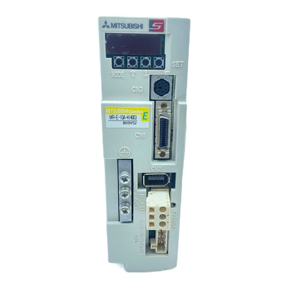
Công ty TNHH DACO www.dacovn.com 1. FUNCTIONS AND CONFIGURATION 1.7 Parts identification (1) MR-E-100A-KH003 or less Name/application Reference Display The 5-digit, seven-segment LED shows the servo status Chapter 6 and alarm number. Operation section Used to perform status display, diagnostic, alarm and parameter setting operations. - Page 25 Công ty TNHH DACO www.dacovn.com 1. FUNCTIONS AND CONFIGURATION (2) MR-E-200A-KH003 Name/application Reference Display The 5-digit, seven-segment LED shows the servo status Chapter 6 and alarm number. Operation section Used to perform status display, diagnostic, alarm and parameter setting operations. DOWN MODE Used to set data.
-
Page 26: Servo System With Auxiliary Equipment
Công ty TNHH DACO www.dacovn.com 1. FUNCTIONS AND CONFIGURATION 1.8 Servo system with auxiliary equipment To prevent an electric shock, always connect the protective earth (PE) terminal WARNING (terminal marked ) of the servo amplifier to the protective earth (PE) of the control box. - Page 27 Công ty TNHH DACO www.dacovn.com 1. FUNCTIONS AND CONFIGURATION (2) MR-E-200A-KH003 Options and auxiliary equipment Reference Options and auxiliary equipment Reference (Note) Circuit breaker Section 13.2.2 Regenerative option Section 13.1.1 Power supply Magnetic contactor Section 13.2.2 Cables Section 13.2.1 MR Configurator Power factor improving reactor Section 13.2.3 Section 13.1.4...
- Page 28 Công ty TNHH DACO www.dacovn.com 2. INSTALLATION 2. INSTALLATION Stacking in excess of the limited number of products is not allowed. Install the equipment to incombustibles. Installing them directly or close to combustibles will led to a fire. Install the equipment on incombustible material. Installing them directly or close to combustibles will lead to a fire.
- Page 29 Công ty TNHH DACO www.dacovn.com 2. INSTALLATION 2.2 Installation direction and clearances The equipment must be installed in the specified direction. Otherwise, a fault may occur. CAUTION Leave specified clearances between the servo amplifier and control box inside walls or other equipment. (1) Installation of one servo amplifier Control box Control box...
- Page 30 Công ty TNHH DACO www.dacovn.com 2. INSTALLATION (3) Others When using heat generating equipment such as the regenerative option, install them with full consideration of heat generation so that the servo amplifier is not affected. Install the servo amplifier on a perpendicular wall in the correct vertical direction. 2.3 Keep out foreign materials (1) When installing the unit in a control box, prevent drill chips and wire fragments from entering the servo amplifier.
- Page 31 Công ty TNHH DACO www.dacovn.com 2. INSTALLATION MEMO 2 - 4...
-
Page 32: Signals And Wiring
Công ty TNHH DACO www.dacovn.com 3. SIGNALS AND WIRING 3. SIGNALS AND WIRING Any person who is involved in wiring should be fully competent to do the work. Before wiring, turn off the power and wait for 15 minutes or more until the charge lamp turns off. -
Page 33: Standard Connection Example
Công ty TNHH DACO www.dacovn.com 3. SIGNALS AND WIRING 3.1 Standard connection example POINT Refer to section 3.7.1 for the connection of the power supply system and to section 3.8 for connection with the servo motor. 3.1.1 Position control mode (1) FX-10GM Positioning module Servo amplifier... - Page 34 Công ty TNHH DACO www.dacovn.com 3. SIGNALS AND WIRING Note 1. To prevent an electric shock, always connect the protective earth (PE) terminal (terminal marked ) of the servo amplifier to the protective earth (PE) of the control box. 2. Connect the diode in the correct direction. If it is connected reversely, the servo amplifier will be faulty and will not output signals, disabling the emergency stop and other protective circuits.
- Page 35 Công ty TNHH DACO www.dacovn.com 3. SIGNALS AND WIRING (2) AD75P (A1SD75P ) Positioning module AD75P Servo amplifier (A1SD75P (Note 8) 10m max. (Note 11) (Note 7) (Note 7) External power READY supply (Note 2) 24VDC Trouble INPS (Note 5) Zero speed PGO(24V) PGO(5V)
- Page 36 Công ty TNHH DACO www.dacovn.com 3. SIGNALS AND WIRING Note 1. To prevent an electric shock, always connect the protective earth (PE) terminal (terminal marked ) of the servo amplifier to the protective earth (PE) of the control box. 2. Connect the diode in the correct direction. If it is connected reversely, the servo amplifier will be faulty and will not output signals, disabling the emergency stop and other protective circuits.
- Page 37 Công ty TNHH DACO www.dacovn.com 3. SIGNALS AND WIRING (3) QD75D (differential driver) Positioning module Servo amplifier QD75D (Note 11) (Note 8) 10m max. (Note 7) (Note 7) External power READY supply RDY COM (Note 2) 24VDC Trouble (Note 5) Zero speed PGO COM CLEAR...
- Page 38 Công ty TNHH DACO www.dacovn.com 3. SIGNALS AND WIRING Note 1. To prevent an electric shock, always connect the protective earth (PE) terminal (terminal marked ) of the servo amplifier to the protective earth (PE) of the control box. 2. Connect the diode in the correct direction. If it is connected reversely, the servo amplifier will be faulty and will not output signals, disabling the emergency stop and other protective circuits.
- Page 39 Công ty TNHH DACO www.dacovn.com 3. SIGNALS AND WIRING 3.1.2 Internal speed control mode Servo amplifier (Note 7) (Note 9) (Note 2) Trouble External (Note 5) power Zero speed supply 24VDC Speed reached 10m max. Ready (Note 7) (Note 3, 4) Emergency stop Servo-on Encoder Z-phase pulse Forward rotation start...
-
Page 40: Internal Connection Diagram Of Servo Amplifier
Công ty TNHH DACO www.dacovn.com 3. SIGNALS AND WIRING 3.2 Internal connection diagram of servo amplifier The following is the internal connection diagram where the signal assignment has been made in the initial status in each control mode. Servo amplifier (Note) (Note) External... -
Page 41: Connectors And Signal Arrangements
Công ty TNHH DACO www.dacovn.com 3. SIGNALS AND WIRING 3.3 I/O signals 3.3.1 Connectors and signal arrangements POINT The pin configurations of the connectors are as viewed from the cable connector wiring section. Refer to the next page for CN1 signal assignment. (1) Signal arrangement MODE MITSUBISHI... - Page 42 Công ty TNHH DACO www.dacovn.com 3. SIGNALS AND WIRING (2) CN1 signal assignment The signal assignment of connector changes with the control mode as indicated below; For the pins which are given parameter No.s in the related parameter column, their signals can be changed using those parameters.
- Page 43 Công ty TNHH DACO www.dacovn.com 3. SIGNALS AND WIRING (3) Symbols and signal names Symbol Signal name Symbol Signal name Servo-on Zero speed Forward rotation stroke end In position Reverse rotation stroke end Speed reached Clear Trouble Speed selection 1 Warning Speed selection 2 Encoder Z-phase pulse (open collector)
-
Page 44: Signal Explanations
Công ty TNHH DACO www.dacovn.com 3. SIGNALS AND WIRING 3.3.2 Signal explanations For the I/O interfaces (symbols in I/O column in the table), refer to section 3.6.2. In the control mode field of the table P : Position control mode, S: Internal speed control mode : Denotes that the signal may be used in the initial setting status. - Page 45 Công ty TNHH DACO www.dacovn.com 3. SIGNALS AND WIRING Control Connector Signal Symbol Functions/applications mode pin No. division Internal torque When using this signal, make it usable by making the setting of parameter DI-1 limit selection No.43 to 48. (Refer to section 3.4.1 (5).) Forward rotation CN1-3 Used to start the servo motor in any of the following directions.
- Page 46 Công ty TNHH DACO www.dacovn.com 3. SIGNALS AND WIRING Control Connector Signal Symbol Functions/applications mode pin No. division Emergency stop CN1-8 Disconnect EMG-SG to bring the servo motor to emergency stop state, in DI-1 which the servo is switched off and the dynamic brake is operated. Connect EMG-SG in the emergency stop state to reset that state.
- Page 47 Công ty TNHH DACO www.dacovn.com 3. SIGNALS AND WIRING (2) Output signals Control Connector Signal Symbol Functions/applications mode pin No. division Trouble CN1-9 ALM-SG are disconnected when power is switched off or the protective DO-1 circuit is activated to shut off the base circuit. Without alarm, ALM-SG are connected within about 1s after power on.
- Page 48 Công ty TNHH DACO www.dacovn.com 3. SIGNALS AND WIRING Control Connector Signal Symbol Functions/applications mode pin No. division Alarm code ACD 0 To use this signal, set " 1" in parameter No.49. DO-1 This signal is output when an alarm occurs. When there is no alarm, ACD 1 respective ordinary signals (RD, INP, SA, ZSP) are output.
- Page 49 Công ty TNHH DACO www.dacovn.com 3. SIGNALS AND WIRING Control Connector Signal Symbol Functions/applications mode pin No. division Encoder Z-phase CN1-21 Outputs the zero-point signal of the encoder. One pulse is output per servo DO-2 pulse motor revolution. OP and LG are connected when the zero-point position is (Open collector) reached.
-
Page 50: Detailed Description Of The Signals
Công ty TNHH DACO www.dacovn.com 3. SIGNALS AND WIRING 3.4 Detailed description of the signals 3.4.1 Position control mode (1) Pulse train input (a) Input pulse waveform selection Encoder pulses may be input in any of three different forms, for which positive or negative logic can be chosen. - Page 51 Công ty TNHH DACO www.dacovn.com 3. SIGNALS AND WIRING (b) Connections and waveforms 1) Open collector system Connect as shown below. Servo amplifier External power supply 24VDC Approx. 1.2k Approx. 1.2k (Note) Note. Pulse train input interface is comprised of a photo coupler. Therefore, it may be any malfunctions since the current is reduced when connect a resistance to a pulse train signal line.
- Page 52 Công ty TNHH DACO www.dacovn.com 3. SIGNALS AND WIRING 2) Differential line driver system Connect as shown below. Servo amplifier Approx. (Note) Approx. Note. Pulse train input interface is comprised of a photo coupler. Therefore, it may be any malfunctions since the current is reduced when connect a resistance to a pulse train signal line.
- Page 53 Công ty TNHH DACO www.dacovn.com 3. SIGNALS AND WIRING (2) In-position (INP) PF-SG are connected when the number of droop pulses in the deviation counter falls within the preset in- position range (parameter No.5). INP-SG may remain connected when low-speed operation is performed with a large value set as the in-position range.
- Page 54 Công ty TNHH DACO www.dacovn.com 3. SIGNALS AND WIRING (5) Torque limit Releasing the torque limit during servo lock may cause the servo motor to CAUTION suddenly rotate according to the position deviation from the instructed position. (a) Torque limit and torque By setting parameter No.28 (internal torque limit 1), torque is always limited to the maximum value during operation.
- Page 55 Công ty TNHH DACO www.dacovn.com 3. SIGNALS AND WIRING 3.4.2 Internal speed control mode (1) Speed setting (a) Speed command and speed The servo motor is run at the speeds set in the parameters. Forward rotation (CCW) Reverse rotation (CW) The following table indicates the rotation direction according to forward rotation start (ST1) and reverse rotation start (ST2) combination.
- Page 56 Công ty TNHH DACO www.dacovn.com 3. SIGNALS AND WIRING (b) Speed selection 1 (SP1), speed selection 2 (SP2), speed selection 3 (SP3) and speed command value By making speed selection 1 (SP1), speed selection 2 (SP2) and speed selection 3 (SP3) usable by setting of parameter No.43 to 47, you can choose the speed command values of internal speed commands 1 to 7.
-
Page 57: Speed Control Mode
Công ty TNHH DACO www.dacovn.com 3. SIGNALS AND WIRING 3.4.3 Position/internal speed control change mode Set "0001" in parameter No.0 to switch to the position/internal speed control change mode. This function is not available in the absolute position detection system. (1) Control change (LOP) Use control change (LOP) to switch between the position control mode and the internal speed control mode from an external contact. - Page 58 Công ty TNHH DACO www.dacovn.com 3. SIGNALS AND WIRING (3) Internal speed setting in speed control mode (a) Speed command and speed The servo motor is run at the speed set in parameter No.8 (internal speed command 1) the forward rotation start (ST1) and reverse rotation start (ST2) are as in section 3.4.2 (1) (a).
- Page 59 Công ty TNHH DACO www.dacovn.com 3. SIGNALS AND WIRING 3.5 Alarm occurrence timing chart When an alarm has occurred, remove its cause, make sure that the operation signal is not being input, ensure safety, and reset the alarm before restarting CAUTION operation.
- Page 60 Công ty TNHH DACO www.dacovn.com 3. SIGNALS AND WIRING 3.6 Interfaces 3.6.1 Common line The following diagram shows the power supply and its common line. External power ALM, etc. supply 24VDC DO-1 SON, etc. DI-1 (Note) PG NG PP NP Isolated LA etc.
- Page 61 Công ty TNHH DACO www.dacovn.com 3. SIGNALS AND WIRING 3.6.2 Detailed description of the interfaces This section gives the details of the I/O signal interfaces (refer to I/O Division in the table) indicated in section 3.3.2. Refer to this section and connect the interfaces with the external equipment. (1) Digital input interface DI-1 Give a signal with a relay or open collector transistor.
- Page 62 Công ty TNHH DACO www.dacovn.com 3. SIGNALS AND WIRING (b) Lamp load Servo amplifier (Note) External power supply ALM, 24VDC 10% etc. Note. If the voltage drop (maximum of 2.6V) interferes with the relay operation, apply high voltage (up to 26.4V) from external source.
- Page 63 Công ty TNHH DACO www.dacovn.com 3. SIGNALS AND WIRING (b) Differential line driver system 1) Interface Servo amplifier Max. input pulse frequency 500kpps 10m or less PP(NP) (Note) Approx. 100 PG(NG) Am26LS31 or equivalent : 2.5V : 0.5V Note. Pulse train input interface is comprised of a photo coupler. Therefore, it may be any malfunctions since the current is reduced when connect a resistance to a pulse train signal line.
- Page 64 Công ty TNHH DACO www.dacovn.com 3. SIGNALS AND WIRING (b) Differential line driver system 1) Interface Max. output current: 35mA Servo amplifier Servo amplifier Am26LS32 or equivalent High-speed photocoupler (LB, LZ) (LB, LZ) (LBR, LZR) (LBR, LZR) 2) Output pulse Servo motor CCW rotation Time cycle (T) is determined by the settings of parameter No.27 and 54.
- Page 65 Công ty TNHH DACO www.dacovn.com 3. SIGNALS AND WIRING 3.7 Input power supply circuit Always connect a magnetic contactor (MC) between the main circuit power supply and L and L of the servo amplifier, and configure the wiring to be able to shut down the power supply on the side of the servo amplifier’s power supply.
- Page 66 Công ty TNHH DACO www.dacovn.com 3. SIGNALS AND WIRING (2) For 1-phase 230VAC power supply Emergency stop CNP1 Servo amplifier Power supply 1-phase 230VAC (Note) Emergency stop Servo-on External power Trouble supply 24VDC Note. To use the built-in regenerative resistor, be sure to connect across P and D of the power supply connector (CNP1). 3.7.2 Terminals Refer to section 11.1 (4) for the signal arrangement.
- Page 67 Công ty TNHH DACO www.dacovn.com 3. SIGNALS AND WIRING 3.7.3 Power-on sequence (1) Power-on procedure 1) Always wire the power supply as shown in above section 3.7.1 using the magnetic contactor with the power supply (three-phase 200V: L , single-phase 230V: L ).
- Page 68 Công ty TNHH DACO www.dacovn.com 3. SIGNALS AND WIRING 3.8 Connection of servo amplifier and servo motor 3.8.1 Connection instructions Insulate the connections of the power supply terminals to prevent an electric WARNING shock. Connect the wires to the correct phase terminals (U, V, W) of the servo amplifier and servo motor.
- Page 69 Công ty TNHH DACO www.dacovn.com 3. SIGNALS AND WIRING 3.8.2 Power supply cable wiring diagrams (1) HF-KE W1-S100 Servo motor (a) When cable length is 10m or less 10m or less MR-PWS1CBL M-A1-L MR-PWS1CBL M-A2-L MR-PWS1CBL M-A1-H Servo amplifier Servo motor MR-PWS1CBL M-A2-H CNP2...
- Page 70 Công ty TNHH DACO www.dacovn.com 3. SIGNALS AND WIRING (b) Connector and signal allotment When the cable length exceeds 10m, fabricate an extension cable as shown below. In this case, the motor power supply cable should be within 2m long. Refer to section 13.1.2 for the wire used for the extension cable.
- Page 71 Công ty TNHH DACO www.dacovn.com 3. SIGNALS AND WIRING (2) HF-SE JW1-S100 servo motor (a) Wiring diagrams Refer to section 13.2 for the cables used for wiring. 50m or less Servo amplifier Servo motor CNP2 (Note 2) 24VDC power Electromagnetic supply for brake interlock Trouble...
- Page 72 Công ty TNHH DACO www.dacovn.com 3. SIGNALS AND WIRING 3.9 Servo motor with electromagnetic brake 3.9.1 Precautions Configure the electromagnetic brake operation circuit so that it is activated not only by the servo amplifier signals but also by an external emergency stop (EMG). Contacts must be open when Circuit must be servo-off, when an trouble (ALM)
- Page 73 Công ty TNHH DACO www.dacovn.com 3. SIGNALS AND WIRING 3.9.3 Timing charts (1) Servo-on signal command (from controller) ON/OFF Tb [ms] after the servo-on (SON) signal is switched off, the servo lock is released and the servo motor coasts. If the electromagnetic brake is made valid in the servo lock status, the brake life may be shorter. Therefore, when using the electromagnetic brake in a vertical lift application or the like, set Delay time (Tb) to about the same as the electromagnetic brake operation delay time to prevent a drop.
- Page 74 Công ty TNHH DACO www.dacovn.com 3. SIGNALS AND WIRING (3) Alarm occurrence Dynamic brake Dynamic brake Electromagnetic brake Servo motor speed Electromagnetic brake (10ms) Base circuit Invalid(ON) Electromagnetic brake Electromagnetic operation delay time brake interlock (MBR) Valid(OFF) No(ON) Trouble (ALM) Yes(OFF) (4) Power off Dynamic brake...
- Page 75 Công ty TNHH DACO www.dacovn.com 3. SIGNALS AND WIRING 3.10 Grounding Ground the servo amplifier and servo motor securely. To prevent an electric shock, always connect the protective earth (PE) terminal WARNING (terminal marked ) of the servo amplifier with the protective earth (PE) of the control box.
-
Page 76: Servo Amplifier Connectors (Cnp1, Cnp2) Wiring Method (When Mr-Ecpn1-B And Mr-Ecpn2-B Of An Option Are Used.)
Công ty TNHH DACO www.dacovn.com 3. SIGNALS AND WIRING 3.11 Servo amplifier connectors (CNP1, CNP2) wiring method (When MR-ECPN1-B and MR-ECPN2-B of an option are used.) POINT For the wire sizes used for wiring, refer to Table 13.1 1), 2) and 3) of section 13.2.1. - Page 77 Công ty TNHH DACO www.dacovn.com 3. SIGNALS AND WIRING (2) Inserting the cable into the connector (a) Applicable flat-blade screwdriver dimensions Always use the screwdriver shown here to do the work. [Unit: mm] (R0.3) (22) (R0.3) (b) When using the flat-blade screwdriver - part 1 1) Insert the screwdriver into the square hole.
- Page 78 Công ty TNHH DACO www.dacovn.com 3. SIGNALS AND WIRING (c) When using the flat-blade screwdriver - part 2 1) Insert the screwdriver into the 2) Push the screwdriver in the 3) With the screwdriver pushed, insert the cable in the square window at top of the direction of arrow.
-
Page 79: Instructions For The 3M Connector
Công ty TNHH DACO www.dacovn.com 3. SIGNALS AND WIRING 3.12 Instructions for the 3M connector When fabricating an encoder cable or the like, securely connect the shielded external conductor of the cable to the ground plate as shown in this section and fix it to the connector shell. External conductor Sheath Core... -
Page 80: Operation
Công ty TNHH DACO www.dacovn.com 4. OPERATION 4. OPERATION 4.1 When switching power on for the first time Before starting operation, check the following. (1) Wiring (a) A correct power supply is connected to the power input terminals (L ) of the servo amplifier. (b) The servo motor power supply terminals (U, V, W) of the servo amplifier match in phase with the power input terminals (U, V, W) of the servo motor. -
Page 81: Startup
Công ty TNHH DACO www.dacovn.com 4. OPERATION 4.2 Startup WARNING Do not operate the switches with wet hands. You may get an electric shock. Before starting operation, check the parameters. Some machines may perform unexpected operation. Take safety measures, e.g. provide covers, to prevent accidental contact of hands and parts (cables, etc.) with the servo amplifier heat sink, regenerative resistor, CAUTION servo motor, etc. - Page 82 Công ty TNHH DACO www.dacovn.com 4. OPERATION (4) Servo-on Switch the servo-on in the following procedure. 1) Switch on power supply. 2) Switch on the servo-on (SON). When placed in the servo-on status, the servo amplifier is ready to operate and the servo motor is locked.
-
Page 83: Internal Speed Control Mode
Công ty TNHH DACO www.dacovn.com 4. OPERATION 4.2.3 Internal speed control mode (1) Power on 1) Switch off the servo-on (SON). 2) When circuit power is switched on, the display shows "r (servo motor speed)", and in two second later, shows data. - Page 84 Công ty TNHH DACO www.dacovn.com 4. OPERATION (6) Stop In any of the following statuses, the servo amplifier interrupts and stops the operation of the servo motor. Refer to section 3.9 for the servo motor equipped with electromagnetic brake. Note that simultaneous ON or simultaneous OFF of forward rotation stroke end (LSP), reverse rotation stroke end (LSN) OFF and forward rotation start (ST1) or reverse rotation start (ST2) signal has the same stop pattern as described below.
- Page 85 Công ty TNHH DACO www.dacovn.com 4. OPERATION MEMO 4 - 6...
-
Page 86: Parameters
Công ty TNHH DACO www.dacovn.com 5. PARAMETERS 5. PARAMETERS Never adjust or change the parameter values extremely as it will make operation CAUTION instable. 5.1 Parameter list 5.1.1 Parameter write inhibit POINT After setting the parameter No.19 value, switch power off, then on to make that setting valid. -
Page 87: Lists
Công ty TNHH DACO www.dacovn.com 5. PARAMETERS 5.1.2 Lists POINT For any parameter whose symbol is preceded by *, set the parameter value and switch power off once, then switch it on again to make that parameter setting valid. The symbols in the control mode column of the table indicate the following modes. P: Position control mode S: Internal speed control mode (1) Item list... - Page 88 Công ty TNHH DACO www.dacovn.com 5. PARAMETERS Control Initial Customer Symbol Name Unit mode value setting *OP2 Function selection 2 0000 *OP3 Function selection 3 (Command pulse selection) 0000 *OP4 Function selection 4 0000 Feed forward gain Zero speed r/min For manufacturer setting For manufacturer setting pulse...
- Page 89 Công ty TNHH DACO www.dacovn.com 5. PARAMETERS Control Initial Customer Symbol Name Unit mode value setting For manufacturer setting 0000 *OP6 Function selection 6 0000 For manufacturer setting 0000 *OP8 Function selection 8 0000 *OP9 Function selection 9 0000 *OPA Function selection A 0000 Serial communication time-out selection...
-
Page 90: Details List
Công ty TNHH DACO www.dacovn.com 5. PARAMETERS (2) Details list Initial Setting Control Class No. Symbol Name and function Unit value range mode *STY Control mode, regenerative option selection 100W Refer to Used to select the control mode and regenerative option. : 0000 name 200W... - Page 91 Công ty TNHH DACO www.dacovn.com 5. PARAMETERS Initial Setting Control Class No. Symbol Name and function Unit value range mode Auto tuning 0105 Refer to Used to selection the response level, etc. for execution of auto tuning. name Refer to chapter 7. function column.
- Page 92 Công ty TNHH DACO www.dacovn.com 5. PARAMETERS Initial Setting Control Class No. Symbol Name and function Unit value range mode In-position range pulse Used to set the in-position signal (INP) output range in the command pulse increments prior to electronic gear calculation. 10000 Position loop gain 1 red/s...
- Page 93 Công ty TNHH DACO www.dacovn.com 5. PARAMETERS Initial Setting Control Class No. Symbol Name and function Unit value range mode Internal speed command 2 r/min 0 to Used to set speed 2 of internal speed commands. instan- taneous permis- sible speed Internal speed command 3 1000...
- Page 94 Công ty TNHH DACO www.dacovn.com 5. PARAMETERS Initial Setting Control Class No. Symbol Name and function Unit value range mode For manufacturer setting Do not change this value by any means. *SNO Station number setting station Used to specify the station number for serial communication. Always set one station to one axis of servo amplifier.
- Page 95 Công ty TNHH DACO www.dacovn.com 5. PARAMETERS Initial Setting Control Class No. Symbol Name and function Unit value range mode *DMD Status display selection 0000 Refer to Used to select the status display shown at power-on. name function column. Selection of status display at power-on 0: Cumulative feedback pulses 1: Servo motor speed...
- Page 96 Công ty TNHH DACO www.dacovn.com 5. PARAMETERS Initial Setting Control Class No. Symbol Name and function Unit value range mode Function selection 2 *OP2 0000 Refer to Used to select restart after instantaneous power failure, name servo lock at a stop in internal speed control mode, and slight vibration suppression control.
- Page 97 Công ty TNHH DACO www.dacovn.com 5. PARAMETERS Initial Setting Control Class No. Symbol Name and function Unit value range mode *OP4 Function selection 4 0000 er to Used to select stop processing at forward rotation stroke end (LSP) name reverse rotation stroke end (LSN) off and choose TLC/VLC output. function column.
- Page 98 Công ty TNHH DACO www.dacovn.com 5. PARAMETERS Initial Setting Control Class No. Symbol Name and function Unit value range mode Internal torque limit 1 Set this parameter to limit servo motor torque on the assumption that the maximum torque is 100[ ]. When 0 is set, torque is not produced.
- Page 99 Công ty TNHH DACO www.dacovn.com 5. PARAMETERS Initial Setting Control Class No. Symbol Name and function Unit value range mode For manufacturer setting Do not change this value by any means. *DIA Input signal automatic ON selection 0000 Refer to Used to set automatic servo-on (SON) forward rotation stroke end name (LSP) reverse rotation stroke end (LSN).
- Page 100 Công ty TNHH DACO www.dacovn.com 5. PARAMETERS Initial Setting Control Class No. Symbol Name and function Unit value range mode *DI2 Input signal selection 2 (CN1-4) 0111 Refer to Allows any input signal to be assigned to CN1-pin 4. name Note that the setting digit and assigned signal differ according to the control mode.
- Page 101 Công ty TNHH DACO www.dacovn.com 5. PARAMETERS Initial Setting Control Class No. Symbol Name and function Unit value range mode *DI3 Input signal selection 3 (CN1-3) 0882 Refer to Allows any input signal to be assigned to CN1-pin 3. name The assignable signals and setting method are the same as in input signal selection 2 (parameter No.43).
- Page 102 Công ty TNHH DACO www.dacovn.com 5. PARAMETERS Initial Setting Control Class No. Symbol Name and function Unit value range mode Input signal selection 6 (CN1-7) *DI6 0000 Refer to Allows any input signal to be assigned to CN1-pin 7. name The assignable signals and setting method are the same as in input signal selection 2 (parameter No.43).
- Page 103 Công ty TNHH DACO www.dacovn.com 5. PARAMETERS Initial Setting Control Class No. Symbol Name and function Unit value range mode *DO1 Output signal selection 1 0000 Refer to Used to select the connector pins to output the alarm code and warning name (WNG).
- Page 104 Công ty TNHH DACO www.dacovn.com 5. PARAMETERS Initial Setting Control Class No. Symbol Name and function Unit value range mode For manufacturer setting 0000 Do not change this value by any means. *OP6 Function selection 6 0000 Refer to Used to select the operation to be performed when the reset (RES) name switches on.
- Page 105 Công ty TNHH DACO www.dacovn.com 5. PARAMETERS Initial Setting Control Class No. Symbol Name and function Unit value range mode *OPA Function selection A 0000 Refer to Used to select the position command acceleration/deceleration time name constant (parameter No.7) control system. function column.
- Page 106 Công ty TNHH DACO www.dacovn.com 5. PARAMETERS Initial Setting Control Class No. Symbol Name and function Unit value range mode Low-pass filter/adaptive vibration suppression control 0000 Refer to Used to selection the low-pass filter and adaptive vibration suppression name control. (Refer to chapter 8.) function column.
- Page 107 Công ty TNHH DACO www.dacovn.com 5. PARAMETERS Initial Setting Control Class No. Symbol Name and function Unit value range mode *CDP Gain changing selection 0000 Refer to Used to select the gain changing condition. (Refer to section 8.5.) name function column.
- Page 108 Công ty TNHH DACO www.dacovn.com 5. PARAMETERS Initial Setting Control Class No. Symbol Name and function Unit value range mode 0 to Internal speed command 5 r/min instan- Used to set speed 5 of internal speed commands. taneous permis- sible speed 0 to Internal speed command 6...
-
Page 109: Detailed Description
Công ty TNHH DACO www.dacovn.com 5. PARAMETERS 5.2 Detailed description 5.2.1 Electronic gear CAUTION Wrong setting can lead to unexpected fast rotation, causing injury. POINT 50 . The guideline of the electronic gear setting range is 50 If the set value is outside this range, noise may be generated during acceleration/ deceleration or operation may not be performed at the preset speed and/or acceleration/deceleration time constants. -
Page 110: Analog Monitor
Công ty TNHH DACO www.dacovn.com 5. PARAMETERS (2) Conveyor setting example For rotation in increments of 0.01 per pulse Servo motor 10000 [pulse/rev] Machine specifications Table Table : 360 /rev Reduction ratio: n 1/18 Servo motor resolution: Pt 10000 [pulses/rev] Timing belt : 4/64 10000 0.01... - Page 111 Công ty TNHH DACO www.dacovn.com 5. PARAMETERS (2) Set content The servo amplifier is factory-set to output the servo motor speed to Analog monitor 1 (MO1) and the torque to Analog monitor 2 (MO2). The setting can be changed as listed below by changing the parameter No.17 value.
- Page 112 Công ty TNHH DACO www.dacovn.com 5. PARAMETERS Note 1. Encoder pulse unit. 2. 8V is outputted at the maximum torque. However, when parameter No.28 76 are set to limit torque, 8V is outputted at the torque highly limited. (3) Analog monitor block diagram 5 - 27...
-
Page 113: Using Forward/Reverse Rotation Stroke End To Change The Stopping Pattern
Công ty TNHH DACO www.dacovn.com 5. PARAMETERS 5.2.3 Using forward/reverse rotation stroke end to change the stopping pattern The stopping pattern is factory-set to make a sudden stop when the forward/reverse rotation stroke end is made valid. A slow stop can be made by changing the parameter No.22 value. Parameter No.22 setting Stopping method Sudden stop... -
Page 114: Position Smoothing
Công ty TNHH DACO www.dacovn.com 5. PARAMETERS 5.2.5 Position smoothing By setting the position command acceleration/deceleration time constant (parameter No.7), you can run the servo motor smoothly in response to a sudden position command. The following diagrams show the operation patterns of the servo motor in response to a position command when you have set the position command acceleration/deceleration time constant. - Page 115 Công ty TNHH DACO www.dacovn.com 5. PARAMETERS MEMO 5 - 30...
-
Page 116: Display And Operation
Công ty TNHH DACO www.dacovn.com 6. DISPLAY AND OPERATION 6. DISPLAY AND OPERATION 6.1 Display flowchart Use the display (5-digit, 7-segment LED) on the front panel of the servo amplifier for status display, parameter setting, etc. Set the parameters before operation, diagnose an alarm, confirm external sequences, and/or confirm the operation status. -
Page 117: Status Display
Công ty TNHH DACO www.dacovn.com 6. DISPLAY AND OPERATION 6.2 Status display The servo status during operation is shown on the 5-digit, 7-segment LED display. Press the "UP" or "DOWN" button to change display data as desired. When the required data is selected, the corresponding symbol appears. -
Page 118: Status Display List
Công ty TNHH DACO www.dacovn.com 6. DISPLAY AND OPERATION 6.2.2 Status display list The following table lists the servo statuses that may be shown. Display Name Symbol Unit Description range Cumulative feedback pulse Feedback pulses from the servo motor encoder are counted and displayed. 99999 pulses The value in excess of... -
Page 119: Changing The Status Display Screen
Công ty TNHH DACO www.dacovn.com 6. DISPLAY AND OPERATION Display Name Symbol Unit Description range Within one-revolution The within one-revolution position is displayed in 100 pulse increments of position high pulse the encoder. The value returns to 0 when it exceeds the maximum number of pulses. 1310 The value is incremented in the CCW direction of rotation. -
Page 120: Diagnostic Mode
Công ty TNHH DACO www.dacovn.com 6. DISPLAY AND OPERATION 6.3 Diagnostic mode Name Display Description Not ready. Indicates that the servo amplifier is being initialized or an alarm has occurred. Sequence Ready. Indicates that the servo was switched on after completion of initialization and the servo amplifier is ready to operate. -
Page 121: Alarm Mode
Công ty TNHH DACO www.dacovn.com 6. DISPLAY AND OPERATION 6.4 Alarm mode The current alarm, past alarm history and parameter error are displayed. The lower 2 digits on the display indicate the alarm number that has occurred or the parameter number in error. Display examples are shown below. -
Page 122: Parameter Mode
Công ty TNHH DACO www.dacovn.com 6. DISPLAY AND OPERATION 6.5 Parameter mode The parameters whose abbreviations are marked* are made valid by changing the setting and then switching power off once and switching it on again. Refer to section 5.1.2. (1) Operation example The following example shows the operation procedure performed after power-on to change the control mode (parameter No.0) to the Internal speed control mode. -
Page 123: External I/O Signal Display
Công ty TNHH DACO www.dacovn.com 6. DISPLAY AND OPERATION 6.6 External I/O signal display The ON/OFF states of the digital I/O signals connected to the servo amplifier can be confirmed. (1) Operation Call the display screen shown after power-on. Using the "MODE" button, show the diagnostic screen. Press UP once. - Page 124 Công ty TNHH DACO www.dacovn.com 6. DISPLAY AND OPERATION (3) Default signal indications (a) Position control mode EMG (CN 1-8) Emergency stop LSN (CN 1-7) Reverse rotation stroke end LSP (CN 1-6) Forward rotation stroke end CR (CN 1-5) Clear RES (CN 1-3) Reset SON (CN 1-4) Servo-on Input signals...
-
Page 125: Output Signal (Do) Forced Output
Công ty TNHH DACO www.dacovn.com 6. DISPLAY AND OPERATION 6.7 Output signal (DO) forced output POINT When the servo system is used in a vertical lift application, turning on the electromagnetic brake interlock (MBR) after assigning it to pin CN1-12 will release the electromagnetic brake, causing a drop. -
Page 126: Test Operation Mode
Công ty TNHH DACO www.dacovn.com 6. DISPLAY AND OPERATION 6.8 Test operation mode The test operation mode is designed to confirm servo operation and not to confirm machine operation. In this mode, do not use the servo motor with the machine. CAUTION Always use the servo motor alone. -
Page 127: Jog Operation
Công ty TNHH DACO www.dacovn.com 6. DISPLAY AND OPERATION 6.8.2 Jog operation Jog operation can be performed when there is no command from the external command device. (1) Operation Connect EMG-SG to start jog operation to use the internal power supply. Hold down the "UP"... -
Page 128: Positioning Operation
Công ty TNHH DACO www.dacovn.com 6. DISPLAY AND OPERATION 6.8.3 Positioning operation POINT The MR Configurator (servo configuration software) is required to perform positioning operation. Positioning operation can be performed once when there is no command from the external command device. (1) Operation Connect EMG-SG to start positioning operation to use the internal power supply. -
Page 129: Motor-Less Operation
Công ty TNHH DACO www.dacovn.com 6. DISPLAY AND OPERATION 6.8.4 Motor-less operation Without connecting the servo motor, you can provide output signals or monitor the status display as if the servo motor is running in response to external input signals. This operation can be used to check the sequence of a host programmable controller or the like. -
Page 130: General Gain Adjustment
Công ty TNHH DACO www.dacovn.com 7. GENERAL GAIN ADJUSTMENT 7. GENERAL GAIN ADJUSTMENT 7.1 Different adjustment methods 7.1.1 Adjustment on a single servo amplifier The gain adjustment in this section can be made on a single servo amplifier. For gain adjustment, first execute auto tuning mode 1. -
Page 131: Adjustment Using Mr Configurator (Servo Configuration Software)
Công ty TNHH DACO www.dacovn.com 7. GENERAL GAIN ADJUSTMENT (2) Adjustment sequence and mode usage START Usage Used when you want to match Interpolation made for 2 or more the position gain (PG1) axes? between 2 or more axes. Interpolation mode Normally not used for other purposes. - Page 132 Công ty TNHH DACO www.dacovn.com 7. GENERAL GAIN ADJUSTMENT 7.2 Auto tuning 7.2.1 Auto tuning mode The servo amplifier has a real-time auto tuning function which estimates the machine characteristic (load inertia moment ratio) in real time and automatically sets the optimum gains according to that value. This function permits ease of gain adjustment of the servo amplifier.
-
Page 133: Auto Tuning Mode Operation
Công ty TNHH DACO www.dacovn.com 7. GENERAL GAIN ADJUSTMENT 7.2.2 Auto tuning mode operation The block diagram of real-time auto tuning is shown below. Load inertia Automatic setting moment Encoder Control gains Command Current Servo PG1,VG1 control motor PG2,VG2,VIC Current feedback Real-time auto Position/speed Set 0 or 1 to turn on. -
Page 134: Adjustment Procedure By Auto Tuning
Công ty TNHH DACO www.dacovn.com 7. GENERAL GAIN ADJUSTMENT 7.2.3 Adjustment procedure by auto tuning Since auto tuning is made valid before shipment from the factory, simply running the servo motor automatically sets the optimum gains that match the machine. Merely changing the response level setting value as required completes the adjustment. -
Page 135: Response Level Setting In Auto Tuning Mode
Công ty TNHH DACO www.dacovn.com 7. GENERAL GAIN ADJUSTMENT 7.2.4 Response level setting in auto tuning mode Set the response (The first digit of parameter No.2) of the whole servo system. As the response level setting is increased, the track ability and settling time for a command decreases, but a too high response level will generate vibration. -
Page 136: Manual Mode 1 (Simple Manual Adjustment)
Công ty TNHH DACO www.dacovn.com 7. GENERAL GAIN ADJUSTMENT 7.3 Manual mode 1 (simple manual adjustment) If you are not satisfied with the adjustment of auto tuning, you can make simple manual adjustment with three parameters. 7.3.1 Operation of manual mode 1 In this mode, setting the three gains of position control gain 1 (PG1), speed control gain 2 (VG2) and speed integral compensation (VIC) automatically sets the other gains to the optimum values according to these gains. - Page 137 Công ty TNHH DACO www.dacovn.com 7. GENERAL GAIN ADJUSTMENT (c)Adjustment description 1) Speed control gain 2 (parameter No.37) This parameter determines the response level of the speed control loop. Increasing this value enhances response but a too high value will make the mechanical system liable to vibrate. The actual response frequency of the speed loop is as indicated in the following expression.
- Page 138 Công ty TNHH DACO www.dacovn.com 7. GENERAL GAIN ADJUSTMENT (c) Adjustment description 1) Position control gain 1 (parameter No.6) This parameter determines the response level of the position control loop. Increasing position control gain 1 improves track ability to a position command but a too high value will make overshooting liable to occur at the time of settling.
-
Page 139: Interpolation Mode
Công ty TNHH DACO www.dacovn.com 7. GENERAL GAIN ADJUSTMENT 7.4 Interpolation mode The interpolation mode is used to match the position control gains of the axes when performing the interpolation operation of servo motors of two or more axes for an X-Y table or the like. In this mode, the position control gain 2 and speed control gain 2 which determine command track ability are set manually and the other parameter for gain adjustment are set automatically. -
Page 140: Special Adjustment Functions
Công ty TNHH DACO www.dacovn.com 8. SPECIAL ADJUSTMENT FUNCTIONS 8. SPECIAL ADJUSTMENT FUNCTIONS POINT The functions given in this chapter need not be used generally. Use them if you are not satisfied with the machine status after making adjustment in the methods in chapter 7. - Page 141 Công ty TNHH DACO www.dacovn.com 8. SPECIAL ADJUSTMENT FUNCTIONS You can use the machine resonance suppression filter 1 (parameter No.58) and machine resonance suppression filter 2 (parameter No.59) to suppress the vibration of two resonance frequencies. Note that if adaptive vibration suppression control is made valid, the machine resonance suppression filter 1 (parameter No.58) is made invalid.
-
Page 142: Adaptive Vibration Suppression Control
Công ty TNHH DACO www.dacovn.com 8. SPECIAL ADJUSTMENT FUNCTIONS POINT If the frequency of machine resonance is unknown, decrease the notch frequency from higher to lower ones in order. The optimum notch frequency is set at the point where vibration is minimal. A deeper notch has a higher effect on machine resonance suppression but increases a phase delay and may increase vibration. -
Page 143: Low-Pass Filter
Công ty TNHH DACO www.dacovn.com 8. SPECIAL ADJUSTMENT FUNCTIONS (2) Parameters The operation of adaptive vibration suppression control selection (parameter No.60). Parameter No.60 Adaptive vibration suppression control selection Choosing "valid" or "held" in adaptive vibration suppression control selection makes the machine resonance suppression filter 1 (parameter No.58) invalid. -
Page 144: Gain Changing Function
Công ty TNHH DACO www.dacovn.com 8. SPECIAL ADJUSTMENT FUNCTIONS 8.5 Gain changing function This function can change the gains. You can change between gains during rotation and gains during stop or can use an external input signal to change gains during operation. 8.5.1 Applications This function is used when. -
Page 145: Parameters
Công ty TNHH DACO www.dacovn.com 8. SPECIAL ADJUSTMENT FUNCTIONS 8.5.3 Parameters When using the gain changing function, always set " 4 " in parameter No.2 (auto tuning) to choose the manual mode of the gain adjustment modes. The gain changing function cannot be used in the auto tuning mode. - Page 146 Công ty TNHH DACO www.dacovn.com 8. SPECIAL ADJUSTMENT FUNCTIONS (1) Parameters No.6, 34 to 38 These parameters are the same as in ordinary manual adjustment. Gain changing allows the values of ratio of load inertia moment to servo motor inertia moment, position control gain 2, speed control gain 2 and speed integral compensation to be changed.
-
Page 147: Gain Changing Operation
Công ty TNHH DACO www.dacovn.com 8. SPECIAL ADJUSTMENT FUNCTIONS 8.5.4 Gain changing operation This operation will be described by way of setting examples. (1) When you choose changing by external input (a) Setting Parameter No. Abbreviation Name Setting Unit Position control gain 1 rad/s Speed control gain 1 1000... - Page 148 Công ty TNHH DACO www.dacovn.com 8. SPECIAL ADJUSTMENT FUNCTIONS (2) When you choose changing by droop pulses (a) Setting Parameter No. Abbreviation Name Setting Unit Position control gain 1 rad/s Speed control gain 1 1000 rad/s Ratio of load inertia moment to Multiplier servo motor inertia moment ( 10...
- Page 149 Công ty TNHH DACO www.dacovn.com 8. SPECIAL ADJUSTMENT FUNCTIONS MEMO 8 - 10...
-
Page 150: Inspection
Công ty TNHH DACO www.dacovn.com 9. INSPECTION 9. INSPECTION Before starting maintenance and/or inspection, turn off the power and wait for 15 minutes or more until the charge lamp turns off. Otherwise, an electric shock may occur. In addition, always confirm from the front of the servo amplifier whether the WARNING charge lamp is off or not. - Page 151 Công ty TNHH DACO www.dacovn.com 9. INSPECTION (c) Servo amplifier cooling fan The cooling fan bearings reach the end of their life in 10,000 to 30,000 hours. Normally, therefore, the cooling fan must be changed in a few years of continuous operation as a guideline. It must also be changed if unusual noise or vibration is found during inspection.
-
Page 152: Troubleshooting
Công ty TNHH DACO www.dacovn.com 10. TROUBLESHOOTING 10. TROUBLESHOOTING 10.1 Trouble at start-up Excessive adjustment or change of parameter setting must not be made as it will CAUTION make operation instable. POINT Using the optional MR Configurator (servo configuration software), you can refer to unrotated servo motor reasons, etc. - Page 153 Công ty TNHH DACO www.dacovn.com 10. TROUBLESHOOTING Start-up sequence Fault Investigation Possible cause Reference Gain adjustment Rotation ripples Make gain adjustment in the Gain adjustment fault Chapter 7 (speed fluctuations) following procedure. are large at low 1. Increase the auto tuning speed.
- Page 154 Công ty TNHH DACO www.dacovn.com 10. TROUBLESHOOTING (2) How to find the cause of position shift Positioning unit Servo amplifier (a) Output pulse Electronic gear (parameters No.3, 4) Machine counter Servo motor (d) Machine stop position M (b) Cumulative command (C) Servo-on (SON), forward pulses rotation stroke end...
-
Page 155: Internal Speed Control Mode
Công ty TNHH DACO www.dacovn.com 10. TROUBLESHOOTING 10.1.2 Internal speed control mode Start-up sequence Fault Investigation Possible cause Reference Power on (Note) LED is not lit. Not improved if connectors 1. Power supply voltage fault LED flickers. CN1, CN2 and CN3 are 2. -
Page 156: When Alarm Or Warning Has Occurred
Công ty TNHH DACO www.dacovn.com 10. TROUBLESHOOTING 10.2 When alarm or warning has occurred POINT As soon as an alarm occurs, turn off Servo-on (SON) and power off the power supply. 10.2.1 Alarms and warning list When a fault occurs during operation, the corresponding alarm or warning is displayed. If any alarm or warning has occurred, refer to section 10.2.2 or 10.2.3 and take the appropriate action. -
Page 157: Remedies For Alarms
Công ty TNHH DACO www.dacovn.com 10. TROUBLESHOOTING 10.2.2 Remedies for alarms When any alarm has occurred, eliminate its cause, ensure safety, then reset the alarm, and restart operation. Otherwise, injury may occur. CAUTION As soon as an alarm occurs, turn off Servo-on (SON) and power off the power supply. - Page 158 Công ty TNHH DACO www.dacovn.com 10. TROUBLESHOOTING Display Name Definition Cause Action AL.1A Motor Wrong combination Wrong combination of servo amplifier Use correct combination. and servo motor connected. combination of servo amplifier error and servo motor. AL.20 Encoder error 2 Communication error 1.
- Page 159 Công ty TNHH DACO www.dacovn.com 10. TROUBLESHOOTING Display Name Definition Cause Action AL.31 Overspeed Speed has 1. Input command pulse frequency Set command pulses correctly. exceeded the exceeded the permissible instantaneous instantaneous speed frequency. permissible speed. 2. Small acceleration/deceleration time Increase acceleration/deceleration time constant caused overshoot to be constant.
- Page 160 Công ty TNHH DACO www.dacovn.com 10. TROUBLESHOOTING Display Name Definition Cause Action AL.35 Command Input pulse 1. Pulse frequency of the command Change the command pulse frequency to a pulse frequency frequency of the pulse is too high. proper value. error command pulse is 2.
- Page 161 Công ty TNHH DACO www.dacovn.com 10. TROUBLESHOOTING Display Name Definition Cause Action AL.51 Overload 2 Machine collision or 1. Machine struck something. 1. Review operation pattern. the like caused max. 2. Install limit switches. output current to flow 2. Wrong connection of servo motor. Connect correctly.
-
Page 162: Remedies For Warnings
Công ty TNHH DACO www.dacovn.com 10. TROUBLESHOOTING 10.2.3 Remedies for warnings POINT When any of the following alarms has occurred, do not resume operation by switching power of the servo amplifier OFF/ON repeatedly. The servo amplifier and servo motor may become faulty. If the power of the servo amplifier is switched OFF/ON during the alarms, allow more than 30 minutes for cooling before resuming operation. - Page 163 Công ty TNHH DACO www.dacovn.com 10. TROUBLESHOOTING MEMO 10 - 12...
-
Page 164: Outline Dimension Drawings
Công ty TNHH DACO www.dacovn.com 11. OUTLINE DIMENSION DRAWINGS 11. OUTLINE DIMENSION DRAWINGS 11.1 Servo amplifiers (1) MR-E-10A-KH003 MR-E-20A-KH003 [Unit: mm] Approx.70 Mass: 0.7 [kg] (1.54 [lb]) Terminal signal layout Mounting Screw PE terminals CNP2 Screw Size: M5 Tightening torque: 3.24 [N m] (28.676 [lb in]) CNP1 Terminal screw: M4... - Page 165 Công ty TNHH DACO www.dacovn.com 11. OUTLINE DIMENSION DRAWINGS (2) MR-E-40A-KH003 [Unit: mm] Approx.70 Mass: 1.1 [kg] (2.43 [lb]) Terminal signal layout Mounting Screw PE terminals CNP2 Screw Size: M5 Tightening torque: 3.24 [N m] (28.676 [lb in]) CNP1 Terminal screw: M4 Tightening torque: 1.2 [N m] (10 .6 [lb in]) 11 - 2...
- Page 166 Công ty TNHH DACO www.dacovn.com 11. OUTLINE DIMENSION DRAWINGS (3) MR-E-70A-KH003 MR-E-100A-KH003 [Unit: mm] Approx. 70 Mass: 1.7 [kg] (3.75 [lb]) Terminal signal layout Mounting Screw PE terminals CNP2 Screw Size: M5 Tightening torque: 3.24 [N m] (28.676 [lb in]) CNP1 Terminal screw: M4 Tightening torque: 1.2 [N m] (10.6 [lb in])
- Page 167 Công ty TNHH DACO www.dacovn.com 11. OUTLINE DIMENSION DRAWINGS (4) MR-E-200A-KH003 [Unit: mm] Approx. 70 Mass: 2.0 [kg] (4.41 [lb]) Terminal signal layout Mounting Screw CNP1 PE terminals Screw Size: M5 Tightening torque: 3.24 [N m] (28.676 [lb in]) Terminal screw: M4 Tightening torque: 1.2 [N m] (10.6 [lb in]) CNP2...
-
Page 168: Connectors
Công ty TNHH DACO www.dacovn.com 11. OUTLINE DIMENSION DRAWINGS 11.2 Connectors (1) Miniature delta ribbon (MDR) system (3M) (a) One-touch lock type [Unit: mm] Logo etc, are indicated here. 12.7 Each type of dimension Connector Shell kit 10126-3000PE 10326-52F0-008 25.8 37.2 14.0 10.0... - Page 169 Công ty TNHH DACO www.dacovn.com 11. OUTLINE DIMENSION DRAWINGS (2) CN2 Connector (Molex) Connector set : 54599-1019 [Unit: mm] 12.5 (3) CN3 Connector (Marushin electric mfg) Connector: MP371/6 [Unit: mm] 44.5 11 - 6...
- Page 170 Công ty TNHH DACO www.dacovn.com 11. OUTLINE DIMENSION DRAWINGS (4) CNP1 CNP2 Connector (Molex) (a) Crimping type [Unit: mm] Variable dimensions Number of Connector [mm] ([in]) Application poles CNP2 Circuit number indication 51240-0300 17.8 (1kW or less) CNP1 51240-0600 32.8 (1kW or less) Crimping tool: 57349-5300 (Molex) Pitch...
- Page 171 Công ty TNHH DACO www.dacovn.com 11. OUTLINE DIMENSION DRAWINGS (b) Insertion type [Unit: mm] Variable dimensions Number of Connector [mm] Application poles CNP2 54927-0310 16.5 (1kW or less) Housing Housing cover CNP1 54927-0610 31.5 (1kW or less) 26.5 Pitch [Unit: mm] Variable dimensions Number of Connector...
-
Page 172: Characteristics
Công ty TNHH DACO www.dacovn.com 12. CHARACTERISTICS 12. CHARACTERISTICS 12.1 Overload protection characteristics An electronic thermal relay is built in the servo amplifier to protect the servo motor and servo amplifier from overloads. Overload 1 (AL.50) occurs if overload operation performed is above the electronic thermal relay protection curve shown in any of Figs 12.1, Overload 2 (AL.51) occurs if the maximum current flew continuously for several seconds due to machine collision, etc. - Page 173 Công ty TNHH DACO www.dacovn.com 12. CHARACTERISTICS (2) Heat dissipation area for enclosed servo amplifier The enclosed control box (hereafter called the control box) which will contain the servo amplifier should be designed to ensure that its temperature rise is within at the ambient temperature of 40 (104 ).
-
Page 174: Dynamic Brake Characteristics
Công ty TNHH DACO www.dacovn.com 12. CHARACTERISTICS 12.3 Dynamic brake characteristics Fig. 12.3 shows the pattern in which the servo motor comes to a stop when the dynamic brake is operated. Use Equation 12.2 to calculate an approximate coasting distance to a stop. The dynamic brake time constant varies with the servo motor and machine operation speeds. -
Page 175: Encoder Cable Flexing Life
Công ty TNHH DACO www.dacovn.com 12. CHARACTERISTICS 12.4 Encoder cable flexing life The flexing life of the cables is shown below. This graph calculated values. Since they are not guaranteed values, provide a little allowance for these values. 1 10 5 10 1 10 a : Long flex life encoder cable... -
Page 176: Options And Auxiliary Equipment
Công ty TNHH DACO www.dacovn.com 13. OPTIONS AND AUXILIARY EQUIPMENT 13. OPTIONS AND AUXILIARY EQUIPMENT Before connecting any option or peripheral equipment, turn off the power and wait for 15 minutes or more until the charge lamp turns off. Otherwise, an electric shock WARNING may occur. - Page 177 Công ty TNHH DACO www.dacovn.com 13. OPTIONS AND AUXILIARY EQUIPMENT (b) To make selection according to regenerative energy Use the following method when regeneration occurs continuously in vertical motion applications or when it is desired to make an in-depth selection of the regenerative option. a.
- Page 178 Công ty TNHH DACO www.dacovn.com 13. OPTIONS AND AUXILIARY EQUIPMENT Subtract the capacitor charging from the result of multiplying the sum total of regenerative energies by the inverse efficiency to calculate the energy consumed by the regenerative option. ER [J] Calculate the power consumption of the regenerative option on the basis of single-cycle operation period tf [s] to select the necessary regenerative option.
- Page 179 Công ty TNHH DACO www.dacovn.com 13. OPTIONS AND AUXILIARY EQUIPMENT (5) Outline drawing (a) MR-RB032 MR-RB12 [Unit: mm] 6 mounting hole MR-RB Terminal block Terminal screw: M3 Tightening torque: 0.5 to 0.6 [N m](4 to 5 [lb in]) Mounting screw Screw size: M5 Tightening torque: 3.24[N m](28.68 [lb in])
- Page 180 Công ty TNHH DACO www.dacovn.com 13. OPTIONS AND AUXILIARY EQUIPMENT (c) MR-RB50 Cooling fan mounting [Unit: mm (in)] screw (2-M3 screw) Terminal block On opposite side 82.5 Terminal screw: M4 Tightening torque: 1.2 [N m](10.6 [lb in]) 7 14 Mounting screw slot Screw : M6 Tightening torque: 5.4 [N m](47.79 [lb in])
-
Page 181: Cables And Connectors
Công ty TNHH DACO www.dacovn.com 13. OPTIONS AND AUXILIARY EQUIPMENT 13.1.2 Cables and connectors POINT Protective structure indicated for cables and connecters is for a cable or connector alone. When the cables and connectors are used to connect the servo amplifier and servo motor, lower protective structure (IP ) applies. - Page 182 Công ty TNHH DACO www.dacovn.com 13. OPTIONS AND AUXILIARY EQUIPMENT Product Model Description Application Standard encoder MR-EKCBL M-L Receptacle: 36210-0100PL Housing: 1-172161-9 Standard cable Refer to (2) (a) in Shell kit: 36310-3200-008 Connector pin: 170359-1 flexing life this section. (3M) (Tyco Electronics or equivalent) IP20 Cable clamp: MTI-0002...
-
Page 183: Analog Monitor, Rs-232C Branch Cable (Mr-E3Cbl15-P)
Công ty TNHH DACO www.dacovn.com 13. OPTIONS AND AUXILIARY EQUIPMENT Product Model Description Application 10) Amplifier power MR-ECNP1-A Connector: 51240-0600 Terminal: 56125-0128 Insulation supply connector (In units of 20 pcs. (Molex or equivalent) (Molex or equivalent) displacement /box) type (Insulation displacement type) MR-E-10A-KH003 to MR-E-100A-... - Page 184 Công ty TNHH DACO www.dacovn.com 13. OPTIONS AND AUXILIARY EQUIPMENT Product Model Description Application 20) Amplifier power MR-ECNP1-A1 Connector: 54241-0600 Terminal: 56125-0128 Insulation supply connector (In units of 20 pcs. (Molex or equivalent) (Molex or equivalent) displacement /box) type (Insulation displacement type) MR-E-200A- KH003...
- Page 185 Công ty TNHH DACO www.dacovn.com 13. OPTIONS AND AUXILIARY EQUIPMENT Product Model Description Application 30) Motor brake cable MR-BKS1CBL M- IP65 Brake connector A1-L Load side Cable length: lead HF-KE W1-S100 2 5 10m 31) Motor brake cable MR-BKS1CBL M- IP65 A1-H Load side...
- Page 186 Công ty TNHH DACO www.dacovn.com 13. OPTIONS AND AUXILIARY EQUIPMENT Product Model Description Application 41) Encoder cable MR-J3JCBL03M- IP20 Encoder connector A2-L Opposite-to- Cable length: 0.3m load side lead HF-KE W1-S100 Refer to section 13.1.2 (2) (c) for details. (2) Encoder cable connector sets If you have fabricated the encoder cable, connect it correctly.
- Page 187 Công ty TNHH DACO www.dacovn.com 13. OPTIONS AND AUXILIARY EQUIPMENT (a) MR-J3ENCBL M-A1-L/H MR-J3ENCBL M-A2-L/H These cables are encoder cables for the HF-KE W1-S100 series servo motors. The numerals in the Cable Length field of the table are the symbols entered in the part of the cable model.
- Page 188 Công ty TNHH DACO www.dacovn.com 13. OPTIONS AND AUXILIARY EQUIPMENT 2) Cable internal wiring diagram MR-J3ENCBL2M-L/-H MR-J3ENCBL5M-L/-H MR-J3ENCBL10M-L/-H Servo amplifier Encoder side side connector connector Plate (Note) Note. When an encoder cable is fabricated, this wire is not required. (b) MR-EKCBL M-L/H POINT The following encoder cables are of four-wire type.
- Page 189 Công ty TNHH DACO www.dacovn.com 13. OPTIONS AND AUXILIARY EQUIPMENT 1) Connection of servo amplifier and servo motor Servo amplifier MR-EKCBL M-L MR-J3JCBL03M-L MR-EKCBL M-H Cable length: 0.3m Servo motor HF-KE W1-S100 Cable model 1) CN2 connector 2) Junction connector MR-EKCBL Receptacle: 36210-0100PL Connector set: 54599-1019...
- Page 190 Công ty TNHH DACO www.dacovn.com 13. OPTIONS AND AUXILIARY EQUIPMENT 2) Internal wiring diagram MR-EKCBL20M-L MR-EKCBL30M-L Servo amplifier side Encoder side Servo amplifier side Encoder side Plate (Note) CONT Plate (Note) MR-EKCBL20M-H MR-EKCBL30M-H MR-EKCBL40M-H Servo amplifier side Encoder side MR-EKCBL50M-H Servo amplifier side Encoder side Plate...
- Page 191 Công ty TNHH DACO www.dacovn.com 13. OPTIONS AND AUXILIARY EQUIPMENT 3) When fabricating the encoder cable When fabricating the cable, prepare the following parts and tool, and fabricate it according to the wiring diagram in 2). Refer to section 13.2.1 for the specifications of the used cable. Parts/tool Description Connector set...
- Page 192 Công ty TNHH DACO www.dacovn.com 13. OPTIONS AND AUXILIARY EQUIPMENT (d) MR-ESCBL M-L (standard flex life model) These encoder cables are used with the HF-SE JW1-S100 servo motors. 1) Model explanation Model: MR-ESCBL Standard flex life Cable length Communication system Symbol Two-wire type (Note) Four-wire type...
- Page 193 Công ty TNHH DACO www.dacovn.com 13. OPTIONS AND AUXILIARY EQUIPMENT b) Encoder cable of 30m or more POINT The communication system of the encoder cable in this wiring diagram is the four-wire type. Set "1 " in parameter No.20. When fabricating an encoder cable, use the MR-ECNS connector set. Referring to the following wiring diagram, you can fabricate an encoder cable of up to 50m.
- Page 194 Công ty TNHH DACO www.dacovn.com 13. OPTIONS AND AUXILIARY EQUIPMENT (e) MR-ESCBL M-H (long flex life model) MR-ENECBL M-H (IP65/IP67-compatible, long flex life model) These encoder cables are used with the HC-SFE series servo motors. 1) Model explanation Model: MR-ESCBL Long flex life Communication system Symbol...
- Page 195 Công ty TNHH DACO www.dacovn.com 13. OPTIONS AND AUXILIARY EQUIPMENT 2) Connection diagram For the pin assignment on the servo amplifier side, refer to section 3.3.1. Servo amplifier Encoder connector Encoder connector Pin Signal Pin Signal Servo motor Encoder cable (Optional or fabricated) CONT Encoder...
- Page 196 Công ty TNHH DACO www.dacovn.com 13. OPTIONS AND AUXILIARY EQUIPMENT b) Encoder cable of 30m or more POINT The communication system of the encoder cable in this wiring diagram is the four-wire type. Set "1 " in parameter No.20. When fabricating an encoder cable, use the MR-ECNS (IP20-compatible model) or MR-ENECNS (IP65/IP67-compatible model) connector set.
- Page 197 Công ty TNHH DACO www.dacovn.com 13. OPTIONS AND AUXILIARY EQUIPMENT (3) Communication cable POINT This cable may not be used with some personal computers. After fully examining the signals of the RS-232C connector, refer to this section and fabricate the cable. (a) Model definition Model: QC30R2 (Cable length 3[m]) (b) Connection diagram for fabrication...
- Page 198 Công ty TNHH DACO www.dacovn.com 13. OPTIONS AND AUXILIARY EQUIPMENT (4) Motor power supply cables These cables are motor power supply cables for the HF-KE W1-S100 servo motors. The numerals in the Cable Length field of the table are the symbols entered in the part of the cable model.
- Page 199 Công ty TNHH DACO www.dacovn.com 13. OPTIONS AND AUXILIARY EQUIPMENT (a) Connection of servo amplifier and servo motor MR-PWS1CBL M-A1-L MR-PWS1CBL M-A1-H MR-PWS2CBL03M-A1-L Servo amplifier Servo motor HF-KE W1-S100 MR-PWS1CBL M-A2-L MR-PWS1CBL M-A2-H For motor power MR-PWS2CBL03M-A2-L supply connector Servo motor HF-KE W1-S100 Cable model 1) For motor power supply connector...
- Page 200 Công ty TNHH DACO www.dacovn.com 13. OPTIONS AND AUXILIARY EQUIPMENT (5) Motor brake cables These cables are motor brake cables for the HF-KE W1-S100 servo motors. The numerals in the Cable Length field of the table are the symbols entered in the part of the cable model.
- Page 201 Công ty TNHH DACO www.dacovn.com 13. OPTIONS AND AUXILIARY EQUIPMENT (a) Connection of servo amplifier and servo motor MR-BKS1CBL M-A1-L MR-BKS1CBL M-A1-H MR-BKS2CBL03M-A1-L Servo motor 24VDC power HF-KE W1-S100 supply for electromagnetic brake MR-BKS1CBL M-A2-L MR-BKS1CBL M-A2-H MR-BKS2CBL03M-A2-L Servo motor HF-KE W1-S100 Cable model 1) For motor brake connector...
- Page 202 Công ty TNHH DACO www.dacovn.com 13. OPTIONS AND AUXILIARY EQUIPMENT 13.1.3 Analog monitor, RS-232C branch cable (MR-E3CBL15-P) (1) Usage The analog monitor, RS-232C branch cable (MR-E3CBL15-P) is designed for use when a personal computer and analog monitor outputs are used at the same time. Servo amplifier Analog monitor, RS-232C branch cable Communication cable...
-
Page 203: Mr Configurator (Servo Configurations Software)
Công ty TNHH DACO www.dacovn.com 13. OPTIONS AND AUXILIARY EQUIPMENT 13.1.4 MR Configurator (servo configurations software) The MR Configurator (servo configurations software MRZJW3-SETUP154E, 154C) uses the communication function of the servo amplifier to perform parameter setting changes, graph display, test operation, etc. on a personal computer. -
Page 204: Auxiliary Equipment
Công ty TNHH DACO www.dacovn.com 13. OPTIONS AND AUXILIARY EQUIPMENT 13.2 Auxiliary equipment Always use the devices indicated in this section or equivalent. To comply with the EN Standard or UL/C-UL (CSA) Standard, use the products which conform to the corresponding standard. 13.2.1 Selection example of wires (1) Wires for power supply wiring The following diagram shows the wires used for wiring. - Page 205 Công ty TNHH DACO www.dacovn.com 13. OPTIONS AND AUXILIARY EQUIPMENT (2) Wires for cables When fabricating a cable, use the wire models given in the following table or equivalent. Table 13.2 Wires for option cables Characteristics of one core (Note 2) Length Core size Number...
-
Page 206: Circuit Breakers, Fuses, Magnetic Contactors
Công ty TNHH DACO www.dacovn.com 13. OPTIONS AND AUXILIARY EQUIPMENT 13.2.2 Circuit breakers, fuses, magnetic contactors Always use one circuit breaker and one magnetic contactor with one servo amplifier. When using a fuse instead of the circuit breaker, use the one having the specifications given in this section. Fuse Servo amplifier Circuit breaker... -
Page 207: Relays
Công ty TNHH DACO www.dacovn.com 13. OPTIONS AND AUXILIARY EQUIPMENT 13.2.4 Relays The following relays should be used with the interfaces. Interface Selection example Input signals (interface DI-1) signals To prevent defective contacts, use a relay for small signal (twin contacts). (Ex.) Omron: type G2A, MY Relay used for digital output signals (interface DO-1) Small relay with 12VDC or 24VDC of rating 40mA or less... -
Page 208: Noise Reduction Techniques
Công ty TNHH DACO www.dacovn.com 13. OPTIONS AND AUXILIARY EQUIPMENT 13.2.6 Noise reduction techniques Noises are classified into external noises which enter the servo amplifier to cause it to malfunction and those radiated by the servo amplifier to cause peripheral devices to malfunction. Since the servo amplifier is an electronic device which handles small signals, the following general noise reduction techniques are required. - Page 209 Công ty TNHH DACO www.dacovn.com 13. OPTIONS AND AUXILIARY EQUIPMENT Noise radiated directly Noises produced Noises transmitted Route 1) from servo amplifier by servo amplifier in the air Noise radiated from the Route 2) power supply cable Noise radiated from Route 3) servo motor cable Magnetic induction...
- Page 210 Công ty TNHH DACO www.dacovn.com 13. OPTIONS AND AUXILIARY EQUIPMENT Noise transmission route Suppression techniques When measuring instruments, receivers, sensors, etc. which handle weak signals and may malfunction due to noise and/or their signal cables are contained in a control box together with the servo amplifier or run near the servo amplifier, such devices may malfunction due to noises transmitted through the air.
- Page 211 Công ty TNHH DACO www.dacovn.com 13. OPTIONS AND AUXILIARY EQUIPMENT (b) Surge suppressor The recommended surge suppressor for installation to an AC relay, AC valve or the like near the servo amplifier is shown below. Use this product or equivalent. Relay Surge suppressor Surge suppressor...
- Page 212 Công ty TNHH DACO www.dacovn.com 13. OPTIONS AND AUXILIARY EQUIPMENT Outline drawing [Unit: mm] Earth plate Clamp section diagram 2- 5 hole 17.5 installation hole L or less (Note)M4 screw Note. Screw hole for grounding. Connect it to the earth plate of the control box. Type Accessory fittings Clamp fitting...
- Page 213 Công ty TNHH DACO www.dacovn.com 13. OPTIONS AND AUXILIARY EQUIPMENT (d) Line noise filter (FR-BSF01) This filter is effective in suppressing noises radiated from the power supply side and output side of the servo amplifier and also in suppressing high-frequency leakage current (zero-phase current) especially within 0.5MHz to 5MHz band.
- Page 214 Công ty TNHH DACO www.dacovn.com 13. OPTIONS AND AUXILIARY EQUIPMENT (f) Varistors for input power supply (Recommended) Varistors are effective to prevent exogenous noise and lightning surge from entering the servo amplifier. When using a varistor, connect it between each phase of the input power supply of the equipment. For varistors, the TND20V-431K and TND20V-471K, manufactured by NIPPON CHEMI-CON, are recommended.
-
Page 215: Leakage Current Breaker
Công ty TNHH DACO www.dacovn.com 13. OPTIONS AND AUXILIARY EQUIPMENT 13.2.7 Leakage current breaker (1) Selection method High-frequency chopper currents controlled by pulse width modulation flow in the AC servo circuits. Leakage currents containing harmonic contents are larger than those of the motor which is run with a commercial power supply. - Page 216 Công ty TNHH DACO www.dacovn.com 13. OPTIONS AND AUXILIARY EQUIPMENT (2) Selection example Indicated below is an example of selecting a leakage current breaker under the following conditions. Servo amplifier Servo motor MR-E-40A-KH003 HF-KE43W1-S100 Use a leakage current breaker generally available. Find the terms of Equation (13.1) from the diagram.
-
Page 217: Emc Filter
Công ty TNHH DACO www.dacovn.com 13. OPTIONS AND AUXILIARY EQUIPMENT 13.2.8 EMC filter For compliance with the EMC Directive of the EN Standard, it is recommended to use the following filter. Some EMC filters are large in leakage current. (1) Combination with the servo amplifier Recommended filter Servo amplifier Mass [kg]([lb]) -
Page 218: Servo Motor
Công ty TNHH DACO www.dacovn.com 14. SERVO MOTOR 14. SERVO MOTOR 14.1 Compliance with the overseas standards 14.1.1 Compliance with EC directives Use the servo motor compatible with the EN Standard. Unless otherwise specified, the handling, performance, specifications and others of the EN Standard- compatible models are the same as those of the standard models. -
Page 219: Introduction
Công ty TNHH DACO www.dacovn.com 14. SERVO MOTOR 14.2 Introduction 14.2.1 Features of servo motor The following table indicates the main features of the servo motor. The items marked are supported as standard. For detailed specifications, refer to the chapter of the servo motor series. Servo motor series Item HF-KE W1-S100... -
Page 220: Parts Identification
Công ty TNHH DACO www.dacovn.com 14. SERVO MOTOR 14.2.3 Parts identification (1) HF-KE W1-S100 For full information of the cable connector, refer to section 13.1.2. Encode cable Power supply connector (Note) Encoder Servo motor shaft Note. The servo motor with electromagnetic brake has the electromagnetic brake connector separately. (2) HF-SE JW1-S100 Power supply connector (Note) Encoder connector... -
Page 221: Electromagnetic Brake Characteristics
Công ty TNHH DACO www.dacovn.com 14. SERVO MOTOR 14.2.4 Electromagnetic brake characteristics The electromagnetic brake is provided to prevent a drop at a power failure or servo alarm occurrence during vertical drive or to hold a shaft at a stop. Do not use it for normal braking (including braking at servo lock). -
Page 222: Servo Motor Shaft Shapes
Công ty TNHH DACO www.dacovn.com 14. SERVO MOTOR 14.2.5 Servo motor shaft shapes In addition to the straight shaft, the keyway shaft and D cut shaft are available as the servo motor shafts. The keyway shaft and D cut shaft cannot be used in frequent start/stop applications. Since we cannot warrant the servo motor against fracture and similar accidents attributable to a loose key, use a friction coupling, etc. -
Page 223: Installation
Công ty TNHH DACO www.dacovn.com 14. SERVO MOTOR 14.3 Installation Stacking in excess of the limited number of products is not allowed. Install the equipment to incombustibles. Installing them directly or close to combustibles will led to a fire. Install the equipment in a load-bearing place in accordance with this Instruction Manual. -
Page 224: Installation Orientation
Công ty TNHH DACO www.dacovn.com 14. SERVO MOTOR 14.3.1 Installation orientation (1) Standard servo motor The following table indicates the installation orientation of the standard servo motor. Servo Motor Series Direction of Installation Remarks HF-KE W1-S100 May be installed in any For installation in the horizontal direction, it is recommended to set the HF-SE JW1-S100 direction. -
Page 225: Permissible Load For The Shaft
Công ty TNHH DACO www.dacovn.com 14. SERVO MOTOR (2) For the servo motor shaft with a keyway, use the screw hole in the shaft end. For the shaft without a keyway, use a friction coupling or the like. (3) When removing the pulley, use a pulley remover to protect the shaft from hard load and or impact. (4) To ensure safety, fit a protective cover or the like on the rotary area, such as the pulley, mounted to the shaft. -
Page 226: Cable
Công ty TNHH DACO www.dacovn.com 14. SERVO MOTOR (1) Do not use the servo motor with its cable soaked in oil or water. (Figure on the right) Cover Servo motor Oil/water pool <Incorrect> Capillary phenomenon (2) When the servo motor is to be installed with the shaft end at top, provide measures so that it is not exposed to oil and water entering from the machine side, gear box, etc. -
Page 227: Inspection
Công ty TNHH DACO www.dacovn.com 14. SERVO MOTOR 14.3.6 Inspection Before starting maintenance and/or inspection, turn off the power and wait for 15 minutes or more until the charge lamp turns off. Otherwise, an electric shock may occur. In addition, always confirm from the front of the servo amplifier whether the WARNING charge lamp is off or not. -
Page 228: Machine Accuracies
Công ty TNHH DACO www.dacovn.com 14. SERVO MOTOR 14.3.8 Machine accuracies The following table indicates the machine accuracies of the servo motor around the output shaft and mounting. (except the optional products) Measuring Flange size Accuracy [mm] position Less than Runout of flange surface to output shaft 0.05 0.06... -
Page 229: Connectors Used For Servo Motor Wiring
Công ty TNHH DACO www.dacovn.com 14. SERVO MOTOR 14.4 Connectors used for servo motor wiring 14.4.1 Selection of connectors Use the connector configuration products given in the table as the connectors for connection with the servo motor. Refer to section 14.4.2 for the compatible connector configuration products. (1) HF-KE W1-S100 Wiring connector Servo motor... - Page 230 Công ty TNHH DACO www.dacovn.com 14. SERVO MOTOR These connectors can be used for the EN Standard and UL/C-UL Standard. Configuration product Connector configuration Servo motor encoder connector Connector (IP65) Crimping tool For Ground clip: 1596970-1 Connector: 1674320-1 For REC. contact: 1596847 1674339-1 (Tyco Electronics) (Tyco Electronics) (Tyco Electronics)
-
Page 231: Wiring Connectors (Connector Configurations D, E, F, G, H)
Công ty TNHH DACO www.dacovn.com 14. SERVO MOTOR 14.4.3 Wiring connectors (Connector configurations D, E, F, G, H) Encoder connector Power supply MS3102A20-29P connector Brake connector MS3102A18-10P MS3102A22-22P CM10-R2P Cable 3) Cable clamp Cable 1) Plug 2) Back shell 1) Plug 2) Back shell 3) Cable clamp 1) Plug (DDK) - Page 232 Công ty TNHH DACO www.dacovn.com 14. SERVO MOTOR 1) Plug 2) Cable clamp Cable 1) Plug 2)Cable clamp Cable 1) Plug (DDK) 2) Cable Clamp (DDK) Connector Servo motor power Cable OD Application configuration supply connector Type Model name Model name [mm] (Reference) CE05-6A18-10SD-D-BSS...
- Page 233 Công ty TNHH DACO www.dacovn.com 14. SERVO MOTOR 1) Plug 2) Cable clamp Cable 1) Plug 2) Cable clamp Cable 1) Plug (DDK) 2) Cable clamp (DDK) Connector Servo motor power Application Cable OD configuration supply connector Type Model name Model name [mm] (Reference) CE05-6A22-22SD-D-BSS...
-
Page 234: Connector Outline Drawings
Công ty TNHH DACO www.dacovn.com 14. SERVO MOTOR 14.5 Connector outline drawings The connector outline drawings for wiring the servo motor are shown below. (1) Tyco Electronics Model Housing : 1-172161-9 Connector pin : 170359-1 170363-1 (loose piece) Crimping tool : 755330-1 [Unit: mm] 23.7... - Page 235 Công ty TNHH DACO www.dacovn.com 14. SERVO MOTOR (3) DDK <Plug> L or less [Unit: mm] W or more Model D/MS3106B18-10S 1 1/8-18UNEF 18.26 52.37 34.31 1-20UNEF 9.53 D/MS3106B20-29S 1 1/4-18UNEF 18.26 55.57 37.28 1 3/16-18UNEF 9.53 D/MS3106B22-22S 1 3/8-18UNEF 18.26 56.57 40.48 1 3/16-18UNEF 9.53 L or less [Unit: mm] Model...
- Page 236 Công ty TNHH DACO www.dacovn.com 14. SERVO MOTOR [Unit: mm] D or less 7.85 or more Model name CE05-6A18-10SD-D-BSS 1 1/8-18UNEF-2B 34.13 32.1 1-20UNEF-2A CE05-6A22-22SD-D-BSS 1 3/8-18UNEF-2B 40.48 38.3 1 3/16-18UNEF-2A [Unit: mm] D or less Model name CE05-8A18-10SD-D-BAS 1 1/8-18UNEF-2B 34.13 69.5 1-20UNEF-2A...
- Page 237 Công ty TNHH DACO www.dacovn.com 14. SERVO MOTOR [Unit: mm] Gasket H or less Model 37.28 34.11 12.16 26.8 18.26 D/MS3106A20-29S(D190) 1 1/4-18UNEF-2B 1 1/8-18UNEF-2A (1.47) (1.34) (0.48) (1.06) (0.72) Contact size 8 or less 8 or less 10 or less 13 or less 13 or less CM10-SP2S-S/M/L...
- Page 238 Công ty TNHH DACO www.dacovn.com 14. SERVO MOTOR <Cable clamp> [Unit: mm] E (Bushing ID) Effective thread length C D (Cable clamp ID) F (Movable range) Shell Model name Bushing size D/MS3057-10A 23.8 30.1 10.3 15.9 14.3 31.7 1-20UNEF AN3420-10 D/MS3057-12A 20.22 23.8...
- Page 239 Công ty TNHH DACO www.dacovn.com 14. SERVO MOTOR 14.6 HF-KE W1-S100 This chapter provides information on the servo motor specifications and characteristics. When using the HF-KE W1-S100 servo motor, always read the Safety Instructions in the beginning of this manual and section 14.1 to 14.4, in addition to this section.
-
Page 240: Hf-Ke W1-S100
Công ty TNHH DACO www.dacovn.com 14. SERVO MOTOR 14.6.2 Standard specifications (1) Standard specifications Servo motor HF-KE W1-S100 (low inertia small capacity) Item Applicable servo MR-E- A-KH003 amplifier/drive unit MR-E- AG-KH003 Rated output [kW] 0.75 Continuous running duty [N m] 0.32 0.64 Rated torque... - Page 241 Công ty TNHH DACO www.dacovn.com 14. SERVO MOTOR 6. In the environment where the servo motor is exposed to oil mist, oil and/or water, the servo motor of the standard specifications may not be usable. Contact us. 7. The vibration direction is as shown in the figure. The value is the one at the part that indicates the maximum value (normally the opposite-to-load side bracket).
-
Page 242: Electromagnetic Brake Characteristics
Công ty TNHH DACO www.dacovn.com 14. SERVO MOTOR 14.6.3 Electromagnetic brake characteristics The electromagnetic brake is provided to prevent a drop at a power failure or CAUTION servo alarm occurrence during vertical drive or to hold a shaft at a stop. Do not use it for normal braking (including braking at servo lock). -
Page 243: Servo Motors With Special Shafts
Công ty TNHH DACO www.dacovn.com 14. SERVO MOTOR 14.6.4 Servo motors with special shafts The servo motors with special shafts indicated by the symbols (K D) in the table are available. K and D are the symbols attached to the servo motor model names. Shaft shape Servo motor Keyway shaft (with key) -
Page 244: Outline Dimension Drawings
Công ty TNHH DACO www.dacovn.com 14. SERVO MOTOR 14.6.5 Outline dimension drawings The dimensions without tolerances are reference dimensions. (1) Standard (Without electromagnetic brake, without reduction gear) Output Inertia moment Mass Model J[ 10 kg m ] (WK [oz in [kg]([Ib]) HF-KE13W1-S100 0.088 (0.48) - Page 245 Công ty TNHH DACO www.dacovn.com 14. SERVO MOTOR Output Inertia moment Mass Model J[ 10 kg m ] (WK [oz in [kg] ([Ib]) HF-KE23W1-S100 0.24 (1.31) 0.94 (2.07) [Unit: mm] 76.6 4- 5.8 mounting hole Motor plate Caution plate for Use hexagon socket (Opposite siede) high temperature...
- Page 246 Công ty TNHH DACO www.dacovn.com 14. SERVO MOTOR Output Inertia moment Mass Model J[ 10 kg m ] (WK [oz in [kg] ([Ib]) HF-KE73W1-S100 1.43 (7.82) 2.9 (6.39) [Unit: mm] 113.8 6.6 mounting hole Caution plate for Use hexagon socket high temperature Motor plate head cap screw...
- Page 247 Công ty TNHH DACO www.dacovn.com 14. SERVO MOTOR (2) With electromagnetic brake Output Static friction torque Inertia moment Mass Model [ N m] ([oz in]) J[ 10 kg m ] (WK [oz in [kg] ([Ib]) HF-KE13BW1-S100 0.32 (45.32) 0.090 (0.49) 0.86 (1.90) [Unit: mm] 123.5...
- Page 248 Công ty TNHH DACO www.dacovn.com 14. SERVO MOTOR Output Static friction torque Inertia moment Mass Model [ N m] ([oz in]) J[ 10 kg m ] (WK [oz in [kg] ([Ib]) HF-KE23BW1-S100 1.3 (184.10) 0.31 (1.70) 1.6 (3.75) [Unit: mm] 4- 5.8 mounting hole 116.1 Use hexagon socket...
- Page 249 Công ty TNHH DACO www.dacovn.com 14. SERVO MOTOR Output Static friction torque Inertia moment Mass Model [ N m] ([oz in]) J[ 10 kg m ] (WK [oz in [kg] ([Ib]) HF-KE43BW1-S100 1.3 (184.10) 0.50 (2.73) 2.1 (4.85) [Unit: mm] 4- 5.8 mounting hole Use hexagon socket Motor plate...
- Page 250 Công ty TNHH DACO www.dacovn.com 14. SERVO MOTOR Output Static friction torque Inertia moment Mass Model [ N m] ([oz in]) J[ 10 kg m ] (WK [oz in [kg] ([Ib]) HF-KE73BW1-S100 2.4 (340) 1.625 (8.91) 3.9 (8.82) [Unit: mm] Motor plate 4- 6.6 mounting hole (Opposite side)
-
Page 251: Hf-Se Jw1-S100
Công ty TNHH DACO www.dacovn.com 14. SERVO MOTOR 14.7 HF-SE JW1-S100 This chapter provides information on the servo motor specifications and characteristics. When using the HF- SE JW1-S100 servo motor, always read the Safety Instructions in the beginning of this manual and section 14.1 to 14.4, in addition to this section. -
Page 252: Standard Specifications
Công ty TNHH DACO www.dacovn.com 14. SERVO MOTOR 14.7.2 Standard specifications (1) Standard specifications Servo motor HF-SE JW1-S100 (medium inertia medium capacity) Item Applicable servo MR-E- A-KH003 amplifier/drive unit MR-E- AG-KH003 Continuous Rated output [kW] running duty [N m] 2.39 4.77 7.16 9.55... - Page 253 Công ty TNHH DACO www.dacovn.com 14. SERVO MOTOR 4. In the environment where the servo motor is exposed to oil mist, oil and/or water, the servo motor of the standard specifications may not be usable. Contact us. 5. The vibration direction is as shown in the figure. The value is the one at the part that indicates the maximum value (normally the opposite-to-load side bracket).
-
Page 254: Electromagnetic Brake Characteristics
Công ty TNHH DACO www.dacovn.com 14. SERVO MOTOR 14.7.3 Electromagnetic brake characteristics The electromagnetic brake is provided to prevent a drop at a power failure or CAUTION servo alarm occurrence during vertical drive or to hold a shaft at a stop. Do not use it for normal braking (including braking at servo lock). -
Page 255: Servo Motors With Special Shafts
Công ty TNHH DACO www.dacovn.com 14. SERVO MOTOR 14.7.4 Servo motors with special shafts The servo motors with special shafts indicated by the symbol (K) in the table is available. K is the symbols attached to the servo motor model names. Shaft shape Servo motor Keyway shaft (without key) -
Page 256: Outline Dimension Drawings
Công ty TNHH DACO www.dacovn.com 14. SERVO MOTOR 14.7.5 Outline dimension drawings The values in yards/pounds are reference values. (1) Standard (Without electromagnetic brake, without reduction gear) Output Inertia moment Mass Model [kW] J[ 10 kg m ] (WK [oz in [kg] ([Ib]) HF-SE52JW1-S100 6.1 (33.4) - Page 257 Công ty TNHH DACO www.dacovn.com 14. SERVO MOTOR Output Inertia moment Mass Model [kW] J[ 10 kg m ] (WK [oz in [kg] ([Ib]) HF-SE152JW1-S100 17.8 (97.3) 8.3 (19.4) [Unit: mm] Motor plate Caution plate Logo plate Motor plate 39.7 9 mounting hole (Opposite side) Caution plate...
- Page 258 Công ty TNHH DACO www.dacovn.com 14. SERVO MOTOR (2) With electromagnetic brake Output Static friction torque Inertia moment Mass Model [kW] [ N m] ([oz in]) J[ 10 kg m ] (WK [oz in [kg] ([Ib]) HF-SE52BJW1-S100 8.5 (1203.7) 8.3 (45.4) 6.7 (15.9) [Unit: mm] 9 mounting hole...
- Page 259 Công ty TNHH DACO www.dacovn.com 14. SERVO MOTOR Output Static friction torque Inertia moment Mass Model [ N m] ([oz in]) J[ 10 kg m ] (WK [oz in [kg] ([Ib]) HF-SE152BJW1-S100 8.5 (1203.7) 20.0 (109.3) 10.3 (23.8) [Unit: mm] 9 mounting hole Use hexagon socket head cap screw.
- Page 260 Công ty TNHH DACO www.dacovn.com 15. MR-E- AG-KH003 SERVO AMPLIFIER COMPATIBLE WITH ANALOG INPUT 15. MR-E- AG-KH003 SERVO AMPLIFIER COMPATIBLE WITH ANALOG INPUT POINT In this chapter, difference of the operation of MR-E- AG-KH003 from that of MR-E- A-KH003 is described. For description not given in this chapter, refer to chapters 1 through 14.
- Page 261 Công ty TNHH DACO www.dacovn.com 15. MR-E- AG-KH003 SERVO AMPLIFIER COMPATIBLE WITH ANALOG INPUT 15.1.2 Function block diagram The function block diagram of this servo is shown below. Regenerative option (Note 3) Servo amplifier Servo motor (Note 3) (Note 3) Diode (Note 1) Relay...
- Page 262 Công ty TNHH DACO www.dacovn.com 15. MR-E- AG-KH003 SERVO AMPLIFIER COMPATIBLE WITH ANALOG INPUT 15.1.3 Servo amplifier standard specifications Servo Amplifier MR-E- -KH003 10AG 20AG 40AG 70AG 100AG 200AG Item 3-phase 200 to 230VAC, 50/60Hz or 1-phase 230VAC, 3-phase 200 to 230VAC, Voltage/frequency 50/60Hz 50/60Hz...
- Page 263 Công ty TNHH DACO www.dacovn.com 15. MR-E- AG-KH003 SERVO AMPLIFIER COMPATIBLE WITH ANALOG INPUT 15.1.4 Model code definition MR-E-40AG-KH003 MR-E-70AG-KH003, MR-E-200AG-KH003 MR-E - AG KH003 or less MR-E-100AG-KH003 MR-E super servo amplifier Series name (Sink I/O interface) Analog input interface Rated output Symbol Rated output [W] Symbol Rated output [W]...
- Page 264 Công ty TNHH DACO www.dacovn.com 15. MR-E- AG-KH003 SERVO AMPLIFIER COMPATIBLE WITH ANALOG INPUT (2) MR-E-200AG-KH003 Name/application Reference Display The 5-digit, seven-segment LED shows the servo status Section 15.5 and alarm number. Operation section Used to perform status display, diagnostic, alarm and parameter setting operations.
- Page 265 Công ty TNHH DACO www.dacovn.com 15. MR-E- AG-KH003 SERVO AMPLIFIER COMPATIBLE WITH ANALOG INPUT 15.1.6 Servo system with auxiliary equipment To prevent an electric shock, always connect the protective earth (PE) terminal WARNING (terminal marked ) of the servo amplifier to the protective earth (PE) of the control box.
- Page 266 Công ty TNHH DACO www.dacovn.com 15. MR-E- AG-KH003 SERVO AMPLIFIER COMPATIBLE WITH ANALOG INPUT (2) MR-E-200AG-KH003 Options and auxiliary equipment Reference Options and auxiliary equipment Reference 3-phase 200V Circuit breaker Section 13.2.2 Regenerative option Section 13.1.1 to 230VAC power supply Magnetic contactor Section 13.2.2 Cables...
- Page 267 Công ty TNHH DACO www.dacovn.com 15. MR-E- AG-KH003 SERVO AMPLIFIER COMPATIBLE WITH ANALOG INPUT 15.2. Signals and wiring 15.2.1 Standard connection example (1) Speed control mode Servo amplifier (Note 7) (Note 2) (Note 9) Trouble (Note 5) External power Zero speed supply 24VDC Speed reached...
- Page 268 Công ty TNHH DACO www.dacovn.com 15. MR-E- AG-KH003 SERVO AMPLIFIER COMPATIBLE WITH ANALOG INPUT Note 1. To prevent an electric shock, always connect the protective earth (PE) terminal (terminal marked ) of the servo amplifier to the protective earth (PE) of the control box. 2.
- Page 269 Công ty TNHH DACO www.dacovn.com 15. MR-E- AG-KH003 SERVO AMPLIFIER COMPATIBLE WITH ANALOG INPUT (2) Torque control mode Servo amplifier (Note 7) (Note 2) (Note 9) Trouble (Note 5) External power Zero speed supply 24VDC Ready 10m or less (Note 7) (Note 3, 4) Emergency stop Encoder Z-phase pulse...
- Page 270 Công ty TNHH DACO www.dacovn.com 15. MR-E- AG-KH003 SERVO AMPLIFIER COMPATIBLE WITH ANALOG INPUT 15.2.2 Internal connection diagram of servo amplifier The following is the internal connection diagram where the signal assignment has been made in the initial status in each control mode. Servo amplifier (Note) (Note)
- Page 271 Công ty TNHH DACO www.dacovn.com 15. MR-E- AG-KH003 SERVO AMPLIFIER COMPATIBLE WITH ANALOG INPUT 15.2.3 Connectors and signal arrangements POINT The pin configurations of the connectors are as viewed from the cable connector wiring section. Refer to the next page for CN1 signal assignment. (1) Signal arrangement MODE MITSUBISHI...
- Page 272 Công ty TNHH DACO www.dacovn.com 15. MR-E- AG-KH003 SERVO AMPLIFIER COMPATIBLE WITH ANALOG INPUT (2) CN1 signal assignment The signal assignment of connector changes with the control mode as indicated below. For the pins which are given parameter No.s in the related parameter column, their signals can be changed using those parameters.
- Page 273 Công ty TNHH DACO www.dacovn.com 15. MR-E- AG-KH003 SERVO AMPLIFIER COMPATIBLE WITH ANALOG INPUT 15.2.4 Signal explanations For the I/O interfaces (symbols in I/O column in the table), refer to section 3.6.2. In the control mode field of the table S: speed control mode, T: Torque control mode : Denotes that the signal may be used in the initial setting status.
- Page 274 Công ty TNHH DACO www.dacovn.com 15. MR-E- AG-KH003 SERVO AMPLIFIER COMPATIBLE WITH ANALOG INPUT Control Connector Signal Symbol Functions/applications mode pin No. division Forward rotation CN1-3 Used to start the servo motor in any of the following directions. DI-1 start (Note) Input signals Servo motor starting direction Stop (servo lock)
- Page 275 Công ty TNHH DACO www.dacovn.com 15. MR-E- AG-KH003 SERVO AMPLIFIER COMPATIBLE WITH ANALOG INPUT Control Connector Signal Symbol Functions/applications mode pin No. division Speed selection 1 <Speed control mode> DI-1 Used to select the command speed for operation. When using SP1 to SP3, make it usable by making the setting of parameter No.43 to 48.
- Page 276 Công ty TNHH DACO www.dacovn.com 15. MR-E- AG-KH003 SERVO AMPLIFIER COMPATIBLE WITH ANALOG INPUT Control Connecto Signal Symbol Functions/applications mode r pin No. division Analog torque CN1-2 To use this signal in the speed control mode, set any of parameters No.43 Analog limit to 48 to make TL available.
- Page 277 Công ty TNHH DACO www.dacovn.com 15. MR-E- AG-KH003 SERVO AMPLIFIER COMPATIBLE WITH ANALOG INPUT (2) Output signals Control Connector mode Signal Symbol Functions/Applications pin No. division Speed reached SA turns off when servo on (SON) turns off or the servo motor speed has DO-1 not reached the preset speed with both forward rotation start (ST1) and reverse rotation start (ST2) turned off.
- Page 278 Công ty TNHH DACO www.dacovn.com 15. MR-E- AG-KH003 SERVO AMPLIFIER COMPATIBLE WITH ANALOG INPUT (3) Power Control Connector mode Signal Symbol Functions/Applications pin No. division Digital I/F power CN1-1 Same as MR-E- A-KH003. (Refer to section 3.3.2 (4).) supply input Open collector CN1-2 power input...
- Page 279 Công ty TNHH DACO www.dacovn.com 15. MR-E- AG-KH003 SERVO AMPLIFIER COMPATIBLE WITH ANALOG INPUT 15.2.5 Detailed description of the signals (1) Speed control mode (a) Speed setting 1) Speed command and speed The servo motor is run at the speeds set in the parameters or at the speed set in the applied voltage of the analog speed command (VC).
- Page 280 Công ty TNHH DACO www.dacovn.com 15. MR-E- AG-KH003 SERVO AMPLIFIER COMPATIBLE WITH ANALOG INPUT 2) Speed selection 1 (SP1), speed selection 2 (SP2), speed selection 3 (SP3) and speed command value by making speed selection 1 (SP1), speed selection 2 (SP2) and speed selection 3 (SP3) usable by setting of parameter No.43 to 47, you can choose the speed command values of internal speed commands 1 to 7.
- Page 281 Công ty TNHH DACO www.dacovn.com 15. MR-E- AG-KH003 SERVO AMPLIFIER COMPATIBLE WITH ANALOG INPUT (c) Torque limit Releasing the torque limit during servo lock may cause the servo motor to CAUTION suddenly rotate according to the position deviation from the instructed position. 1) Torque limit and torque By setting parameter No.28 (internal torque limit 1), torque is always limited to the maximum value during operation.
- Page 282 Công ty TNHH DACO www.dacovn.com 15. MR-E- AG-KH003 SERVO AMPLIFIER COMPATIBLE WITH ANALOG INPUT (2) Torque control mode (a) Torque command 1) Torque command and torque A relationship between the applied voltage of the analog torque command (TC) and the torque by the servo motor is shown below.
- Page 283 Công ty TNHH DACO www.dacovn.com 15. MR-E- AG-KH003 SERVO AMPLIFIER COMPATIBLE WITH ANALOG INPUT 2) Analog torque command offset Using parameter No.30, the offset voltage of 999 to 999mV can be added to the TC applied voltage as shown below. Max.
- Page 284 Công ty TNHH DACO www.dacovn.com 15. MR-E- AG-KH003 SERVO AMPLIFIER COMPATIBLE WITH ANALOG INPUT Generally, make connection as shown below. Servo amplifier 10 to 2) Speed selection 1(SP1)/speed selection 2(SP2)/speed selection 3(SP3) and speed limit values Choose any of the speed settings made by the internal speed limits 1 to 7 using speed selection 1(SP1), speed selection 2(SP2) and speed selection 3(SP3) or the speed setting made by the analog speed limit command (VLA), as indicated below.
- Page 285 Công ty TNHH DACO www.dacovn.com 15. MR-E- AG-KH003 SERVO AMPLIFIER COMPATIBLE WITH ANALOG INPUT (3) Speed/torque control change mode Set "0003" in parameter No.0 to switch to the speed/torque control change mode. (a) Control change (LOP) Use control change (LOP) to switch between the speed control mode and the torque control mode from an external contact.
- Page 286 Công ty TNHH DACO www.dacovn.com 15. MR-E- AG-KH003 SERVO AMPLIFIER COMPATIBLE WITH ANALOG INPUT 15.3 Startup Do not operate the switches with wet hands. You may get an electric shock. WARNING Before starting operation, check the parameters. Some machines may perform unexpected operation.
- Page 287 Công ty TNHH DACO www.dacovn.com 15. MR-E- AG-KH003 SERVO AMPLIFIER COMPATIBLE WITH ANALOG INPUT (3) Parameter setting Set the parameters according to the structure and specifications of the machine. Refer to chapter 5 for the parameter definitions and to section 6.5 for the setting method. Parameter No.
- Page 288 Công ty TNHH DACO www.dacovn.com 15. MR-E- AG-KH003 SERVO AMPLIFIER COMPATIBLE WITH ANALOG INPUT (c) Emergency stop (EMG) OFF The base circuit is shut off and the dynamic brake is operated to bring the servo motor to a sudden stop. Alarm AL.E6 (servo emergency stop warning) occurs.
- Page 289 Công ty TNHH DACO www.dacovn.com 15. MR-E- AG-KH003 SERVO AMPLIFIER COMPATIBLE WITH ANALOG INPUT 15.3.2 Torque control mode (1) Power on 1) Switch off the servo-on (SON). 2) When power is switched on, the display shows "U (torque command voltage)", and in two second later, shows data.
- Page 290 Công ty TNHH DACO www.dacovn.com 15. MR-E- AG-KH003 SERVO AMPLIFIER COMPATIBLE WITH ANALOG INPUT (6) Stop In any of the following statuses, the servo amplifier interrupts and stops the operation of the servo motor. Refer to section 3.9 for the servo motor equipped with electromagnetic brake. (a) Servo-on (SON) OFF The base circuit is shut off and the servo motor coasts.
- Page 291 Công ty TNHH DACO www.dacovn.com 15. MR-E- AG-KH003 SERVO AMPLIFIER COMPATIBLE WITH ANALOG INPUT 15.4 Parameters POINT Before changing the settings of parameters No.20 through 84, cancel write protection while referring to section 5.1.1. For any parameter whose symbol is preceded by *, set the parameter value and switch power off once, then switch it on again to make that parameter setting valid.
- Page 292 Công ty TNHH DACO www.dacovn.com 15. MR-E- AG-KH003 SERVO AMPLIFIER COMPATIBLE WITH ANALOG INPUT Control Initial Customer Class No. Symbol Name Unit mode value setting *OP2 Function selection 2 0000 For manufacturer setting 0000 *OP4 Function selection 4 0000 For manufacturer setting Zero speed r/min Analog speed command maximum speed...
- Page 293 Công ty TNHH DACO www.dacovn.com 15. MR-E- AG-KH003 SERVO AMPLIFIER COMPATIBLE WITH ANALOG INPUT Control Initial Customer Class No. Symbol Name Unit mode value setting *CDP Gain changing selection 0000 Gain changing condition (Note 2) Gain changing time constant For manufacturer setting Internal speed command 4 r/min Internal speed limit 4...
- Page 294 Công ty TNHH DACO www.dacovn.com 15. MR-E- AG-KH003 SERVO AMPLIFIER COMPATIBLE WITH ANALOG INPUT 15.4.2 Details list Initial Setting Control Class No. Symbol Name and function Unit value range mode *STY Control mode, regenerative option selection 100W Refer to Used to select the control mode and regenerative option. : 0000 name 200W...
- Page 295 Công ty TNHH DACO www.dacovn.com 15. MR-E- AG-KH003 SERVO AMPLIFIER COMPATIBLE WITH ANALOG INPUT Initial Setting Control Class No. Symbol Name and function Unit value range mode Auto tuning 0105 Refer to Used to selection the response level, etc. for execution of auto tuning. name Refer to chapter 7.
- Page 296 Công ty TNHH DACO www.dacovn.com 15. MR-E- AG-KH003 SERVO AMPLIFIER COMPATIBLE WITH ANALOG INPUT Initial Setting Control Class No. Symbol Name and function Unit value range mode 0 to Internal speed command 1 r/min instan- Used to set speed 1 of internal speed commands. taneous permi- Internal speed limit 1...
- Page 297 Công ty TNHH DACO www.dacovn.com 15. MR-E- AG-KH003 SERVO AMPLIFIER COMPATIBLE WITH ANALOG INPUT Initial Setting Control Class No. Symbol Name and function Unit value range mode Torque command time constant Used to set the constant of a low-pass filter in response to the torque 20000 command.
- Page 298 Công ty TNHH DACO www.dacovn.com 15. MR-E- AG-KH003 SERVO AMPLIFIER COMPATIBLE WITH ANALOG INPUT Initial Setting Control Class No. Symbol Name and function Unit value range mode Analog monitor output 0100 Refer to Used to selection the signal provided to the analog monitor (MO1) name analog monitor (MO2) output.
- Page 299 Công ty TNHH DACO www.dacovn.com 15. MR-E- AG-KH003 SERVO AMPLIFIER COMPATIBLE WITH ANALOG INPUT Initial Setting Control Class No. Symbol Name and function Unit value range mode *BLK Parameter block 0000 Refer to Used to select the reference and write ranges of the parameters. name Operation can be performed for the parameters marked function...
- Page 300 Công ty TNHH DACO www.dacovn.com 15. MR-E- AG-KH003 SERVO AMPLIFIER COMPATIBLE WITH ANALOG INPUT Initial Setting Control Class No. Symbol Name and function Unit value range mode *OP2 Function selection 2 0000 Refer to Used to select restart after instantaneous power failure, name servo lock at a stop in speed control mode, and slight vibration suppression control.
- Page 301 Công ty TNHH DACO www.dacovn.com 15. MR-E- AG-KH003 SERVO AMPLIFIER COMPATIBLE WITH ANALOG INPUT Initial Setting Control Class No. Symbol Name and function Unit value range mode *OP4 Function selection 4 0000 Refer to Used to select stop processing at forward rotation stroke end (LSP) name reverse rotation stroke end (LSN) off, choose TLC/VLC output and choose VC/VLA voltage averaging.
- Page 302 Công ty TNHH DACO www.dacovn.com 15. MR-E- AG-KH003 SERVO AMPLIFIER COMPATIBLE WITH ANALOG INPUT Initial Setting Control Class No. Symbol Name and function Unit value range mode *ENR Encoder output pulses 4000 pulse/ Used to set the encoder pulses (A-phase or B-phase) output by the servo amplifier.
- Page 303 Công ty TNHH DACO www.dacovn.com 15. MR-E- AG-KH003 SERVO AMPLIFIER COMPATIBLE WITH ANALOG INPUT Initial Setting Control Class No. Symbol Name and function Unit value range mode Analog torque command offset Used to set the offset voltage of the analog torque command (TC). Analog torque limit offset Used to set the offset voltage of the analog torque limit (TLA).
- Page 304 Công ty TNHH DACO www.dacovn.com 15. MR-E- AG-KH003 SERVO AMPLIFIER COMPATIBLE WITH ANALOG INPUT Initial Setting Control Class No. Symbol Name and function Unit value range mode *DIA Input signal automatic ON selection 0000 Refer to Used to set automatic servo-on (SON) forward rotation stroke end name (LSP) reverse rotation stroke end (LSN).
- Page 305 Công ty TNHH DACO www.dacovn.com 15. MR-E- AG-KH003 SERVO AMPLIFIER COMPATIBLE WITH ANALOG INPUT Initial Setting Control Class No. Symbol Name and function Unit value range mode *DI2 Input signal selection 2 (CN1-4) 0111 Refer to Allows any input signal to be assigned to CN1-pin 4. name Note that the setting digit and assigned signal differ according to the control mode.
- Page 306 Công ty TNHH DACO www.dacovn.com 15. MR-E- AG-KH003 SERVO AMPLIFIER COMPATIBLE WITH ANALOG INPUT Initial Setting Control Class No. Symbol Name and function Unit value range mode *DI3 Input signal selection 3 (CN1-3) 0882 Refer to Allows any input signal to be assigned to CN1-pin 3. name The assignable signals and setting method are the same as in input signal selection 2 (parameter No.43).
- Page 307 Công ty TNHH DACO www.dacovn.com 15. MR-E- AG-KH003 SERVO AMPLIFIER COMPATIBLE WITH ANALOG INPUT Initial Setting Control Class No. Symbol Name and function Unit value range mode Input signal selection 6 (CN1-7) *DI6 0000 Refer to Allows any input signal to be assigned to CN1-pin 7. name The assignable signals and setting method are the same as in input signal selection 2 (parameter No.43).
- Page 308 Công ty TNHH DACO www.dacovn.com 15. MR-E- AG-KH003 SERVO AMPLIFIER COMPATIBLE WITH ANALOG INPUT Initial Setting Control Class No. Symbol Name and function Unit value range mode *DO1 Output signal selection 1 0000 Refer to Used to select the connector pins to output the alarm code and warning name (WNG).
- Page 309 Công ty TNHH DACO www.dacovn.com 15. MR-E- AG-KH003 SERVO AMPLIFIER COMPATIBLE WITH ANALOG INPUT Initial Setting Control Class No. Symbol Name and function Unit value range mode For manufacturer setting 0000 Do not change this value by any means. *OP6 Function selection 6 0000 Refer to...
- Page 310 Công ty TNHH DACO www.dacovn.com 15. MR-E- AG-KH003 SERVO AMPLIFIER COMPATIBLE WITH ANALOG INPUT Initial Setting Control Class No. Symbol Name and function Unit value range mode Machine resonance suppression filter 1 0000 Refer to Used to selection the machine resonance suppression filter. name (Refer to section 8.2.) function...
- Page 311 Công ty TNHH DACO www.dacovn.com 15. MR-E- AG-KH003 SERVO AMPLIFIER COMPATIBLE WITH ANALOG INPUT Initial Setting Control Class No. Symbol Name and function Unit value range mode Low-pass filter/adaptive vibration suppression control 0000 Refer to Used to selection the low-pass filter and adaptive vibration suppression name control.
- Page 312 Công ty TNHH DACO www.dacovn.com 15. MR-E- AG-KH003 SERVO AMPLIFIER COMPATIBLE WITH ANALOG INPUT Initial Setting Control Class No. Symbol Name and function Unit value range mode *CDP Gain changing selection 0000 Refer to Used to select the gain changing condition. (Refer to section 8.5.) name function column.
- Page 313 Công ty TNHH DACO www.dacovn.com 15. MR-E- AG-KH003 SERVO AMPLIFIER COMPATIBLE WITH ANALOG INPUT Initial Setting Control Class No. Symbol Name and function Unit value range mode Internal torque limit 2 Set this parameter to limit servo motor torque on the assumption that the maximum torque is 100[].
- Page 314 Công ty TNHH DACO www.dacovn.com 15. MR-E- AG-KH003 SERVO AMPLIFIER COMPATIBLE WITH ANALOG INPUT 15.5 Display and operation POINT For the alarm mode, parameter mode output signal (DO) forcible output and test operation mode, refer to chapter 6. 15.5.1 Display flowchart Use the display (5-digit, 7-segment LED) on the front panel of the servo amplifier for status display, parameter setting, etc.
- Page 315 Công ty TNHH DACO www.dacovn.com 15. MR-E- AG-KH003 SERVO AMPLIFIER COMPATIBLE WITH ANALOG INPUT 15.5.2 Status display (1) Status display list The following table lists the servo statuses that may be shown. Display Name Symbol Unit Description range Cumulative feedback pulse Feedback pulses from the servo motor encoder are counted and displayed.
- Page 316 Công ty TNHH DACO www.dacovn.com 15. MR-E- AG-KH003 SERVO AMPLIFIER COMPATIBLE WITH ANALOG INPUT (2) Changing the status display screen The status display item of the servo amplifier display shown at power-on can be changed by changing the parameter No.18 settings. The item displayed in the initial status changes with the control mode as follows.
- Page 317 Công ty TNHH DACO www.dacovn.com 15. MR-E- AG-KH003 SERVO AMPLIFIER COMPATIBLE WITH ANALOG INPUT 15.5.3 Diagnostic mode Name Display Description Not ready. Indicates that the servo amplifier is being initialized or an alarm has occurred. Sequence Ready. Indicates that the servo was switched on after completion of initialization and the servo amplifier is ready to operate.
- Page 318 Công ty TNHH DACO www.dacovn.com 15. MR-E- AG-KH003 SERVO AMPLIFIER COMPATIBLE WITH ANALOG INPUT Name Display Description Press the "SET" button to show the motor series ID of the servo motor Motor series ID currently connected. Press the "SET" button to show the motor type ID of the servo motor Motor type ID currently connected.
- Page 319 Công ty TNHH DACO www.dacovn.com 15. MR-E- AG-KH003 SERVO AMPLIFIER COMPATIBLE WITH ANALOG INPUT 15.5.4 External I/O signal display The ON/OFF states of the digital I/O signals connected to the servo amplifier can be confirmed. (1) Operation Call the display screen shown after power-on. Using the "MODE"...
- Page 320 Công ty TNHH DACO www.dacovn.com 15. MR-E- AG-KH003 SERVO AMPLIFIER COMPATIBLE WITH ANALOG INPUT (3) Default signal indications (a) Speed control mode EMG (CN 1-8) Emergency stop LSN (CN 1-7) Reverse rotation stroke end LSP (CN 1-6) Forward rotation stroke end ST2 (CN 1-5) Reverse rotation start ST1 (CN 1-3) Forward rotation start SON (CN 1-4) Servo-on...
- Page 321 Công ty TNHH DACO www.dacovn.com 15. MR-E- AG-KH003 SERVO AMPLIFIER COMPATIBLE WITH ANALOG INPUT 15.6. Troubleshooting 15.6.1 Trouble at start-up The following faults may occur at start-up. If any of such faults occurs, take the corresponding action. (1) Speed control mode Start-up sequence Fault Investigation...
- Page 322 Công ty TNHH DACO www.dacovn.com 15. MR-E- AG-KH003 SERVO AMPLIFIER COMPATIBLE WITH ANALOG INPUT (2) Torque control mode Start-up sequence Fault Investigation Possible cause Reference Power on (Note) LED is not lit. Not improved if connectors 1. Power supply voltage fault LED flickers.
- Page 323 Công ty TNHH DACO www.dacovn.com 15. MR-E- AG-KH003 SERVO AMPLIFIER COMPATIBLE WITH ANALOG INPUT 15.6.2 Alarms and warning list POINT Configure up a circuit which will detect the trouble (ALM) signal and turn off the servo-on (SON) signal at occurrence of an alarm. When a fault occurs during operation, the corresponding alarm or warning is displayed.
-
Page 324: Appendix
Công ty TNHH DACO www.dacovn.com APPENDIX App. 1 Change of connector sets to the RoHS compatible products The following connector sets have been changed to RoHS compliant since September 2006. RoHS compliant and non-RoHS compliant connector sets may be mixed based on availability. Only the components of the connector set that have changed are listed below. -
Page 325: App. 2 Hf-Ke Hf-Se Servo Motor
Công ty TNHH DACO www.dacovn.com APPENDIX App. 2 HF-KE HF-SE servo motor App. 2.1 Combination with MR-E- A-KH003/MR-E- AG-KH003 servo amplifier The following table lists combinations of MR-E- A-KH003/MR-E- AG-KH003 servo amplifiers and HF- KE HF-SE servo motors. The same combinations apply to the models with electromagnetic brakes. Servo motors Servo amplifier HF-KE... - Page 326 Công ty TNHH DACO www.dacovn.com APPENDIX App. 2.2 Cable connector The following cables are used for connection with the MR-E- A-KH003/AG-KH003 servo amplifier and HF-KE or HF-SE servo motor. Those indicated by broken lines in the figure are not options. The figure shows the configuration between the servo amplifier and servo motor.
- Page 327 Công ty TNHH DACO www.dacovn.com APPENDIX Product Model Description Application Standard encoder MR-EKCBL M-L Receptacle: 36210-0100PL Housing: 1-172161-9 Standard cable Refer to (2) (a) in Shell kit: 36310-3200-008 Connector pin: 170359-1 flexing life this section. (3M) (Tyco Electronics or equivalent) IP20 Cable clamp: MTI-0002 Connector set: 54599-1019...
- Page 328 Công ty TNHH DACO www.dacovn.com APPENDIX Product Model Description Application 10) Motor power MR-PWCNS5 Plug: CE05-6A22-22SD-D-BSS IP65 supply connector (For HF-SP202 Cable clamp: CE3057-12A-1-D IP67 352 motor) (DDK) Example of applicable cable Wire size: 5.5mm (AWG10) to 8mm (AWG8) Cable finish D: 12.5 to 16mm 11) Brake connector MR-BKCNS1 Straight plug:...
- Page 329 Công ty TNHH DACO www.dacovn.com APPENDIX App. 2.3 HF-KE series This chapter provides information on the servo motor specifications and characteristics. App. 2.3.1 Model name make up HF-KE Appearance Series name Shaft type (Special shaft) Symbol (Note) Shaft shape HF-KE Standard None 13 to 73...
- Page 330 Công ty TNHH DACO www.dacovn.com APPENDIX App. 2.3.2 Standard specifications (1) Standard specifications Servo motor HF-KE series(low inertia small capacity) Item Applicable servo MR-E- A-KH003 amplifier/drive unit MR-E- AG-KH003 Rated output [kW] 0.75 Continuous running duty [N m] 0.32 0.64 Rated torque (Note 1) [oz in]...
- Page 331 Công ty TNHH DACO www.dacovn.com APPENDIX 6. In the environment where the servo motor is exposed to oil mist, oil and/or water, the servo motor of the standard specifications may not be usable. Contact us. 7. The vibration direction is as shown in the figure. The value is the one at the part that indicates the maximum value (normally the opposite-to-load side bracket).
- Page 332 Công ty TNHH DACO www.dacovn.com APPENDIX App. 2.3.3 Electromagnetic brake characteristics The electromagnetic brake is provided to prevent a drop at a power failure or CAUTION servo alarm occurrence during vertical drive or to hold a shaft at a stop. Do not use it for normal braking (including braking at servo lock).
- Page 333 Công ty TNHH DACO www.dacovn.com APPENDIX App. 2.3.4 Servo motors with special shafts The servo motors with special shafts indicated by the symbols (K D) in the table are available. K and D are the symbols attached to the servo motor model names. Shaft shape Servo motor Keyway shaft (with key)
- Page 334 Công ty TNHH DACO www.dacovn.com APPENDIX App. 2.3.5 Outline dimension drawings The dimensions without tolerances are reference dimensions. (1) Standard (Without electromagnetic brake, without reduction gear) Output Inertia moment Mass Model J[ 10 kg m ] (WK [oz in [kg]([Ib]) HF-KE13 0.088 (0.48) 0.56 (1.24)
- Page 335 Công ty TNHH DACO www.dacovn.com APPENDIX Output Inertia moment Mass Model J[ 10 kg m ] (WK [oz in [kg] ([Ib]) HF-KE43 0.42 (2.30) 1.5 (3.5) [Unit: mm] 112.5 4- 5.8mounting hole Motor plate Use hexagon socket (Opposite side) head cap screw Caution plate TUV plate Motor plate...
- Page 336 Công ty TNHH DACO www.dacovn.com APPENDIX (2) With electromagnetic brake Output Static friction torque Inertia moment Mass Model [ N m] ([oz in]) J[ 10 kg m ] (WK [oz in [kg] ([Ib]) HF-KE13B 0.32 (45.32) 0.090 (0.49) 0.86 (1.90) [Unit: mm] 2- 4.5mounting hole Use hexagon socket...
- Page 337 Công ty TNHH DACO www.dacovn.com APPENDIX Output Static friction torque Inertia moment Mass Model [ N m] ([oz in]) J[ 10 kg m ] (WK [oz in [kg] ([Ib]) HF-KE23B 1.3 (184.10) 0.31 (1.70) 1.6 (3.75) [Unit: mm] 130.1 4- 5.8mounting hole Use hexagon socket head cap screw Motor plate...
- Page 338 Công ty TNHH DACO www.dacovn.com APPENDIX Output Static friction torque Inertia moment Mass Model [ N m] ([oz in]) J[ 10 kg m ] (WK [oz in [kg] ([Ib]) HF-KE43B 1.3 (184.10) 0.50 (2.73) 2.1 (4.85) [Unit: mm] 4- 5.8 mounting hole Use hexagon socket head cap screw Motor plate...
- Page 339 Công ty TNHH DACO www.dacovn.com APPENDIX Output Static friction torque Inertia moment Mass Model [ N m] ([oz in]) J[ 10 kg m ] (WK [oz in [kg] ([Ib]) HF-KE73B 2.4 (340) 1.625 (8.91) 3.9 (8.82) [Unit: mm] 4- 6.6 mounting hole Use hexagon socket head cap screw Motor plate...
- Page 340 Công ty TNHH DACO www.dacovn.com APPENDIX App. 2.4 HF-SE series This chapter provides information on the servo motor specifications and characteristics. App. 2.4.1 Model name make up HF-SE Appearance Series name Shaft type Symbol Shaft shape Standard None (Straight shaft) (Note) With keyway Note: Without key Electromagnetic brake...
- Page 341 Công ty TNHH DACO www.dacovn.com APPENDIX App. 2.4.2 Standard specifications (1) Standard specifications Servo motor HF-SE series (medium inertia medium capacity) Item Applicable servo MR-E- A-KH003 amplifier/drive unit MR-E- AG-KH003 Continuous Rated output [kW] running duty [N m] 2.39 4.77 7.16 9.55 Rated torque...
- Page 342 Công ty TNHH DACO www.dacovn.com APPENDIX 4. In the environment where the servo motor is exposed to oil mist, oil and/or water, the servo motor of the standard specifications may not be usable. Contact us. 5. The vibration direction is as shown in the figure. The value is the one at the part that indicates the maximum value (normally the opposite-to-load side bracket).
- Page 343 Công ty TNHH DACO www.dacovn.com APPENDIX App. 2.4.3 Electromagnetic brake characteristics The electromagnetic brake is provided to prevent a drop at a power failure or CAUTION servo alarm occurrence during vertical drive or to hold a shaft at a stop. Do not use it for normal braking (including braking at servo lock).
- Page 344 Công ty TNHH DACO www.dacovn.com APPENDIX App. 2.4.4 Servo motors with special shafts The servo motors with special shafts indicated by the symbol (K) in the table is available. K is the symbols attached to the servo motor model names. Shaft shape Servo motor Keyway shaft (without key)
- Page 345 Công ty TNHH DACO www.dacovn.com APPENDIX App. 2.4.5 Outline dimension drawings The values in yards/pounds are reference values. (1) Standard (Without electromagnetic brake, without reduction gear) Output Inertia moment Mass Model [kW] J[ 10 kg m ] (WK [oz in [kg] ([Ib]) HF-SE52 6.1 (33.4)
- Page 346 Công ty TNHH DACO www.dacovn.com APPENDIX Output Inertia moment Mass Model [kW] J[ 10 kg m ] (WK [oz in [kg] ([Ib]) HF-SE152 17.8 (97.3) 8.3 (19.4) [Unit: mm] Motor plate (Opposite side) 39.7 Caution plate 4- 9 mounting hole Motor plate Caution plate Use hexagon socket...
- Page 347 Công ty TNHH DACO www.dacovn.com APPENDIX (2) With electromagnetic brake Output Static friction torque Inertia moment Mass Model [kW] [ N m] ([oz in]) J[ 10 kg m ] (WK [oz in [kg] ([Ib]) HF-SE52B 8.5 (1203.7) 8.3 (45.4) 6.7 (15.9) [Unit: mm] 154.5 9 mounting hole...
- Page 348 Công ty TNHH DACO www.dacovn.com APPENDIX Output Static friction torque Inertia moment Mass Model [ N m] ([oz in]) J[ 10 kg m ] (WK [oz in [kg] ([Ib]) HF-SE152B 8.5 (1203.7) 20.0 (109.3) 10.3 (23.8) [Unit: mm] 198.5 4- 9 mounting hole Use hexagon socket head cap screw.
- Page 349 Công ty TNHH DACO www.dacovn.com REVISIONS *The manual number is given on the bottom left of the back cover. Print data *Manual number Revision Apr.,2008 SH(NA)030071-A First edition SH(NA)030071-A...
- Page 350 Công ty TNHH DACO www.dacovn.com MODEL MODEL CODE HEAD OFFICE : TOKYO BLDG MARUNOUCHI TOKYO 100-8310 This Instruction Manual uses recycled paper. SH (NA) 030071-A (0804) MEE Printed in Japan Specifications subject to change without notice.
Need help?
Do you have a question about the EZMOTION Super MR-E Series and is the answer not in the manual?
Questions and answers
Como faço para configurar este equipamento
To configure the Mitsubishi Electric Super MR-E Series equipment:
1. Power Supply Connection:
- For MR-E-70AG-KH003 or lower, use a 1-phase 230VAC power supply connected to terminals L and L; leave L open.
2. Wiring:
- Connect the servo amplifier to the command device using CN1 and CN3.
- Connect the servo motor to U, V, W terminals.
- Use a magnetic contactor and circuit breaker as specified in Section 13.2.2.
- Use a power factor improving reactor if needed (Section 13.2.3).
3. Software Setup:
- Use MR Configurator (servo configuration software) to adjust settings.
- For positioning, connect EMG-SG and use the "Forward" or "Reverse" buttons in the software to move the motor.
4. Auto Tuning and Gain Adjustment:
- Start with Auto Tuning Mode 1.
- If results are unsatisfactory, proceed in this order: Auto Tuning Mode 2, Manual Mode 1, then Manual Mode 2.
- Each mode adjusts parameters like PG1, PG2, GD2, VG1, VG2, and VIC.
5. Positioning Operation Settings:
- Default travel distance: 10000 pulses (0–9999999 range).
- Default speed: 200 r/min (adjustable to max allowable speed).
- Acceleration/deceleration time: 1000 ms (0–50000 ms range).
Use the MR Configurator software to make all adjustments and execute operations.
This answer is automatically generated
Namaskar sir Company mein dil Eka machine Sathi error code number 37 parameter coding Mala send karne
The error code number 37 parameter coding for the Mitsubishi Electric Super MR-E Series machine is "VIC Speed integral compensation."
This answer is automatically generated