
Subscribe to Our Youtube Channel
Related Manuals for Mitsubishi Electric MR-J4 B Series


Summary of Contents for Mitsubishi Electric MR-J4 B Series
- Page 1 General-Purpose AC Servo SSCNET /H Interface AC Servo MODEL MR-J4-_B SERVO AMPLIFIER INSTRUCTION MANUAL...
- Page 16 1. FUNCTIONS AND CONFIGURATION 1. FUNCTIONS AND CONFIGURATION 1.1 Summary The Mitsubishi MELSERVO-J4 series general-purpose AC servo has further higher performance and higher functions compared to the previous MELSERVO-J3 series. MR-J4-B servo amplifier is connected to controllers, including a servo system controller, on the high-speed synchronous network SSCNET III/H.
- Page 17 1. FUNCTIONS AND CONFIGURATION 1.2 Function block diagram The function block diagram of this servo is shown below. (1) MR-J4-500B or less Power factor improving Regenerative DC reactor option Servo amplifier Servo motor (Note 4) ( 4) Diode Dynamic brake stack Relay MCCB...
- Page 18 1. FUNCTIONS AND CONFIGURATION (2) MR-J4-700B Power factor improving Regenerative DC reactor option Servo amplifier (Note 2) Servo motor P4 ( 2) Diode Dynamic brake stack Relay circuit MCCB (Note 1) ( 1) Current Power detector supply Regene- CHARGE TR rative TR CHARGE lamp...
- Page 19 1. FUNCTIONS AND CONFIGURATION 1.3 Servo amplifier standard specifications Model MR-J4- 100B 200B 350B 500B 700B Rated voltage 3-phase 170 V AC Output Rated current 11.0 17.0 28.0 37.0 Power 3-phase or 1-phase 200 V AC to 240 V AC, supply/Freque 3-phase 200 V AC to 240 V AC, 50 Hz/60 Hz 50 Hz /60 Hz...
- Page 20 1. FUNCTIONS AND CONFIGURATION Model MR-J4- 100B 200B 350B 500B 700B Oper 0 C to 55 C (non-freezing) ation Ambient temperature Stora -20 C to 65 C (non-freezing) Oper ation Ambient 90% RH or less (non-condensing) humidity Stora Environment Indoors (no direct sunlight), Ambience free from corrosive gas, flammable gas, oil mist, dust, and dirt Max.
- Page 21 1. FUNCTIONS AND CONFIGURATION 1.4 Combinations of servo amplifiers and servo motors Servo amplifier Rotary servo motor Linear servo motor (primary Direct drive motor side) MR-J4-10B HG-KR053, HG-KR13 HG-MR053, HG-MR13 MR-J4-20B HG-KR23 LM-U2PAB-05M-0SS0 TM-RFM002C20 HG-MR23 LM-U2PBB-07M-1SS0 MR-J4-40B HG-KR43 LM-H3P2A-07P-BSS0 TM-RFM004C20 HG-MR43 LM-H3P3A-12P-CSS0 LM-K2P1A-01M-2SS1...
- Page 22 1. FUNCTIONS AND CONFIGURATION 1.5 Function list The following table lists the functions of this servo. For details of the functions, refer to the reference field. Detailed Function Description explanation Position control mode This servo is used as a position control servo. Speed control mode This servo is used as a speed control servo.
- Page 23 1. FUNCTIONS AND CONFIGURATION Detailed Function Description explanation This function continuously monitors the servo status and records the status transition before and after an alarm for a fixed period of time. You can check the recorded data on the drive recorder window on MR Configurator2 by clicking the "Graph" button. However, the drive recorder will not operate on the following conditions.
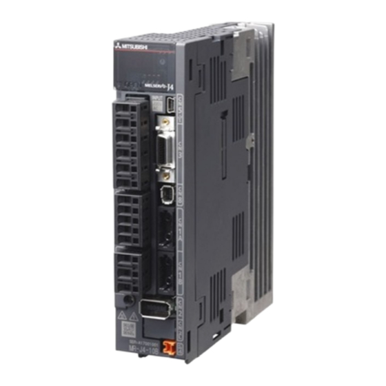
- Page 24 1. FUNCTIONS AND CONFIGURATION 1.7 Structure 1.7.1 Parts identification (1) MR-J4-200B or less Detailed Name/Application explanati Display Chapter The 3-digit, seven-segment LED shows the servo status and the alarm number. Axis selection rotary switch (SW1) Used to set the axis No. of servo amplifier. Inside of the display cover Section Control axis setting switch (SW2)
- Page 25 1. FUNCTIONS AND CONFIGURATION (2) MR-J4-350B Detailed The broken line area is the same as MR-J4-200B or less. MR-J4-200B Name/Application explanati Main circuit power supply connector (CNP1) Section Connect the input power supply. Section Rating plate Section Servo motor power supply connector (CNP3) Section Connect the servo motor.
- Page 26 1. FUNCTIONS AND CONFIGURATION (3) MR-J4-500B POINT The servo amplifier is shown with the front cover open. The front cover cannot be removed. Detailed The broken line area is the same as MR-J4-200B or less. MR-J4-200B Name/Application explanati Control circuit terminal block (TE2) Section Used to connect the control circuit power supply.
- Page 27 1. FUNCTIONS AND CONFIGURATION (4) MR-J4-700B POINT The servo amplifier is shown without the front cover. For removal of the front cover, refer to section 1.7.2. Detailed The broken line area is the same as MR-J4-200B or less. MR-J4-200B Name/Application explanati Power factor improving reactor terminal block (TE3) Used to connect the DC reactor.
- Page 28 1. FUNCTIONS AND CONFIGURATION 1.7.2 Removal and reinstallation of the front cover Before removing or installing the front cover, turn off the power and wait for 15 minutes or more until the charge lamp turns off. Then, confirm that the voltage CAUTION between P+ and N- is safe with a voltage tester and others.
- Page 29 1. FUNCTIONS AND CONFIGURATION Reinstallation of the front cover Front cover setting tab 1) Insert the front cover setting tabs into the sockets of 2) Push down the cover, supporting at point A). servo amplifier (2 places). Setting tab 3) Press the cover against the terminal box until the installing knobs click.
- Page 30 1. FUNCTIONS AND CONFIGURATION 1.8 Configuration including auxiliary equipment POINT Equipment other than the servo amplifier and servo motor are optional or recommended products. (1) MR-J4-200B or less R S T (Note 2) ( 2) Power supply Molded case circuit Personal (MCCB) breaker (MCCB)
- Page 31 1. FUNCTIONS AND CONFIGURATION (2) MR-J4-350B R S T (Note 2) ( 2) Power supply Molded case circuit (MCCB) Personal breaker (MCCB) computer MR Configurator2 (Note 3) ( 3) Magnetic contactor (MC) (MC) (Note 1) ( 1) Junction terminal block Line noise filter To safety relay or MR-J3-...
- Page 32 1. FUNCTIONS AND CONFIGURATION (3) MR-J4-500B R S T (Note 2) ( 2) Power supply Molded case circuit Personal breaker (MCCB) (MCCB) computer MR Configurator2 (Note 3) ( 3) Magnetic contactor (MC) (MC) (Note 1) ( 1) Junction terminal block Line noise To safety relay or MR-J3- filter...
- Page 33 1. FUNCTIONS AND CONFIGURATION (4) MR-J4-700B R S T (Note 2) ( 2) Power supply Personal computer Molded case circuit MR Configurator2 (MCCB) breaker (MCCB) (Note 3) ( 3) Magnetic contactor Junction (MC) (MC) terminal block (Note 1) ( 1) To safety relay or MR-J3- MR-J3-D05 D05 safety logic unit...
- Page 34 2. INSTALLATION 2. INSTALLATION WARNING To prevent electric shock, ground each equipment securely. Stacking in excess of the specified number of product packages is not allowed. Install the equipment on incombustible material. Installing it directly or close to combustibles will lead to a fire. Install the servo amplifier and the servo motor in a load-bearing place in accordance with the Instruction Manual.
- Page 35 2. INSTALLATION 2.1 Installation direction and clearances The equipment must be installed in the specified direction. Otherwise, it may cause a malfunction. CAUTION Leave specified clearances between the servo amplifier and the cabinet walls or other equipment. Otherwise, it may cause a malfunction. (1) 7 kW or less (a) Installation of one servo amplifier Cabinet...
- Page 36 2. INSTALLATION (b) Installation of two or more servo amplifiers POINT Close mounting is possible depending on the capacity of the servo amplifier. Refer to section 1.3 for availability of close mounting. When mounting the servo amplifiers closely, do not install the servo amplifier whose depth is larger than that of the left side servo amplifier since CNP1, CNP2, and CNP3 connectors cannot be disconnected.
- Page 37 2. INSTALLATION (3) When installing the cabinet in a place where toxic gas, dirt and dust exist, conduct an air purge (force clean air into the cabinet from outside to make the internal pressure higher than the external pressure) to prevent such materials from entering the cabinet.
- Page 38 2. INSTALLATION (3) Precautions for migrating plasticizer added materials Generally, soft polyvinyl chloride (PVC), polyethylene resin (PE) and fluorine resin contain non-migrating plasticizer and they do not affect the optical characteristic of SSCNET III cable. However, some wire sheaths and cable ties, which contain migrating plasticizer (phthalate ester), may affect MR-J3BUS_M and MR-J3BUS_M-A cables (plastic).
- Page 39 2. INSTALLATION (7) Twisting If optical fiber is twisted, it will become the same stress added condition as when local lateral pressure or bend is added. Consequently, transmission loss increases, and the breakage of optical fiber may occur. (8) Disposal When incinerating optical cable (cord) used for SSCNET III, hydrogen fluoride gas or hydrogen chloride gas which is corrosive and harmful may be generated.
- Page 40 2. INSTALLATION 2.6 Parts having service lives Service lives of the following parts are listed below. However, the service lives vary depending on operation and environment. If any fault is found in the parts, they must be replaced immediately regardless of their service lives.
- Page 41 2. INSTALLATION MEMO 2 - 8...
- Page 42 3. SIGNALS AND WIRING 3. SIGNALS AND WIRING Any person who is involved in wiring should be fully competent to do the work. Before wiring, turn off the power and wait for 15 minutes or more until the charge lamp turns off. Then, confirm that the voltage between P+ and N- is safe with a voltage tester and others.
- Page 43 3. SIGNALS AND WIRING Connect the servo amplifier power output (U, V, and W) to the servo motor power input (U, V, and W) directly. Do not let a magnetic contactor, etc. intervene. Otherwise, it may cause a malfunction. Servo amplifier Servo motor Servo amplifier Servo motor...
- Page 44 3. SIGNALS AND WIRING Configure the wiring so that the main circuit power supply is shut off and the servo-on command turned off after deceleration to a stop due to an alarm occurring, an enabled servo forced stop, or an enabled controller forced stop.
- Page 45 3. SIGNALS AND WIRING (1) For 3-phase 200 V AC to 240 V AC power supply of MR-J4-10B to MR-J4-350B (Note 4) Malfunction EMG stop switch Servo amplifier Servo motor MCCB CNP1 (Note 7) 3-phase CNP3 (Note 6) 200 V AC to Motor 240 V AC (Note 10)
- Page 46 3. SIGNALS AND WIRING (2) For 1-phase 200 V AC to 240 V AC power supply of MR-J4-10B to MR-J4-70B POINT Connect the 1-phase 200 V AC to 240 V AC power supply to L1 and L3. One of the connecting destination is different from MR-J3 Series Servo Amplifier. When using MR-J4 as a replacement for MR-J3, be careful not to connect the power to L2.
- Page 47 3. SIGNALS AND WIRING (3) MR-J4-500B (Note 4) Malfunction EMG stop switch Servo amplifier Servo motor MCCB (Note 7) 3-phase (Note 6) 200 V AC to Motor 240 V AC (Note 10) (Note 1) (Note 3) Encoder Encoder cable (Note 2) (Note 8) Main circuit power supply 24 V DC...
- Page 48 3. SIGNALS AND WIRING (4) MR-J4-700B (Note 4) Malfunction EMG stop switch Servo amplifier Servo motor MCCB MCCB (Note 7) 1-phase (Note 6) Built-in 200 V AC to regenerative Motor 240 V AC resistor (Note 2) (Note 10) (Note 3) Encoder Encoder cable...
- Page 49 3. SIGNALS AND WIRING 3.2 I/O signal connection example POINT EM2 has the same function as EM1 in the torque control mode. 3.2.1 For sink I/O interface Servo amplifier (Note 16) Short-circuit connector (Packed with the servo amplifier) (Note 12) 10 m or less 10 m or less DICOM...
- Page 50 3. SIGNALS AND WIRING Note 1. To prevent an electric shock, always connect the protective earth (PE) terminal (marked ) of the servo amplifier to the protective earth (PE) of the cabinet. Connect the diode in the correct direction. If it is connected reversely, the servo amplifier will malfunction and will not output signals, disabling EM2 (Forced stop 2) and other protective circuits.
- Page 51 3. SIGNALS AND WIRING 3.2.2 For source I/O interface POINT For notes, refer to section 3.2.1. Servo amplifier (Note 16) Short-circuit connector (Packed with the servo amplifier) (Note 12) (Note 15) (Note 12) (Note 2) Main circuit power supply (Note 3, 4) Electromagnetic brake interlock 13 MBR Forced stop 2...
- Page 52 3. SIGNALS AND WIRING 3.3 Explanation of power supply system 3.3.1 Signal explanations POINT For the layout of connector and terminal block, refer to chapter 9 DIMENSIONS. Connection target Abbreviation Description (Application) Supply the following power to L1, L2, and L3. For 1-phase 200 V AC to 240 V AC, connect the power supply to L1 and L3.
- Page 53 3. SIGNALS AND WIRING 3.3.2 Power-on sequence (1) Power-on procedure 1) Always wire the power supply as shown in above section 3.1 using the magnetic contactor with the main circuit power supply (3-phase: L1, L2, and L3, 1-phase: L1 and L3). Configure up an external sequence to switch off the magnetic contactor as soon as an alarm occurs.
- Page 54 3. SIGNALS AND WIRING 3.3.3 Wiring CNP1, CNP2, and CNP3 POINT For the sizes of wires used for wiring, refer to section 11.11. MR-J3-500B or more do not have these connectors. Use the servo amplifier power supply connector for wiring CNP1, CNP2 and CNP3. (1) Connectors (a) MR-J4-10B to MR-J4-100B Servo amplifier...
- Page 55 3. SIGNALS AND WIRING (2) Cable connection procedure (a) Cable making Refer to table 3.1 and 3.2 for stripped length of cable insulator. The appropriate stripped length of cables depends on their type, etc. Set the length considering their status. Insulator Core Stripped length...
- Page 56 3. SIGNALS AND WIRING 3.4 Connectors and pin assignment POINT The pin assignment of the connectors are as viewed from the cable connector wiring section. For the STO I/O signal connector (CN8), refer to chapter 13. In the case of the CN3 connector, securely connect the shielded external conductor of the cable to the ground plate and fix it to the connector shell.
- Page 57 3. SIGNALS AND WIRING The servo amplifier front view shown is that of the MR-J4-20B or less. Refer to chapter 9 DIMENSIONS for the appearances and connector layouts of the other servo amplifiers. CN5(USB connector) Refer to section 11.8 For the STO I/O signal connector, refer to chapter DOCOM DICOM...
- Page 58 3. SIGNALS AND WIRING 3.5 Signal (device) explanations For the I/O interfaces (symbols in I/O division column in the table), refer to section 3.8.2.In the control mode field of the table The pin No.s in the connector pin No. column are those in the initial status. 3.5.1 Input device Connector Device...
- Page 59 3. SIGNALS AND WIRING 3.5.2 Output device (1) Output device pin The following shows the output device pins and parameters for assigning devices. Connector pin No. Parameter Initial device I/O division CN3-13 [Pr. PD07] CN3-15 [Pr. PD09] DO-1 CN3-9 [Pr. PD08] (2) Output device explanations Device Abbreviation...
- Page 60 3. SIGNALS AND WIRING Device Abbreviation Function and application Warning When warning has occurred, WNG turns on. Without warning occurring, WNG turns off about 2.5 s to 3.5 s after power-on. Battery warning BWNG BWNG turns on when [AL. 92 Battery cable disconnection warning] or [AL. 9F Battery warning] has occurred.
- Page 61 3. SIGNALS AND WIRING 3.6 Forced stop deceleration function POINT When alarms not related to the forced stop function occur, control of motor deceleration can not be guaranteed. (Refer to section 8.1.) In the torque control mode, the forced stop deceleration function is not available. 3.6.1 Forced stop deceleration function (SS1) When EM2 is turned off, dynamic brake will start to stop the servo motor after forced stop deceleration.
- Page 62 3. SIGNALS AND WIRING 3.6.2 Base circuit shut-off delay time function The base circuit shut-off delay time function is used to maintain power at the motor for a specified time delay after a forced stop activation (EM2 goes off). The time between completion of EM2 (Forced stop 2) or activation of MBR (Electromagnetic brake interlock) due to an alarm occurrence, and the time at which the base is cut, is the base cut delay time and is set by [Pr.
- Page 63 3. SIGNALS AND WIRING 3.6.3 Vertical axis freefall prevention function The vertical axis freefall prevention function avoids machine damage by pulling up the shaft slightly the following case. When the servo motor is used for operating vertical axis, the servo motor electromagnetic brake and the base circuit shut-off delay time function avoid dropping axis at forced stop.
- Page 64 3. SIGNALS AND WIRING 3.6.4 Residual risks of the forced stop function (EM2) (1) The forced stop function is not available for alarms that activate the dynamic brake when the alarms occur. (2) When an alarm that activates the dynamic brake during forced stop deceleration occurs, the braking distance until the servo motor stops will be longer than that of normal forced stop deceleration without the dynamic brake.
- Page 65 3. SIGNALS AND WIRING 3.7 Alarm occurrence timing chart When an alarm has occurred, remove its cause, make sure that the operation CAUTION signal is not being input, ensure safety, and reset the alarm before restarting operation. POINT In the torque control mode, the forced stop deceleration function is not available. To deactivate the alarm, cycle the control circuit power or give the error reset or CPU reset command from the servo system controller.
- Page 66 3. SIGNALS AND WIRING (2) When the forced stop deceleration function is invalid Alarm occurrence Braking by the dynamic brake Dynamic brake + Braking by the electromagnetic brake Servo motor speed 0 r/min Base circuit (Energy supply to the servo motor) Servo amplifier No alarm Alarm No.
- Page 67 3. SIGNALS AND WIRING 3.8 Interfaces 3.8.1 Internal connection diagram POINT Refer to section 13.3.1 for the CN8 connector. Servo amplifier Forced stop 2 Approximately 6.2 k DICOM (Note) (Note 2) (Note 1) Approximately (Note 3) 6.2 k 24 V DC DICOM DOCOM Isolated...
- Page 68 3. SIGNALS AND WIRING 3.8.2 Detailed description of interfaces This section provides the details of the I/O signal interfaces (refer to the I/O division in the table) given in section 3.5. Refer to this section and make connection with the external device. (1) Digital input interface DI-1 Turn on/off the input signal with a relay or open collector transistor.
- Page 69 3. SIGNALS AND WIRING (3) Encoder output pulses DO-2 (differential line driver type) (a) Interface Max. output current: 35 mA Servo amplifier Servo amplifier Am26LS32 or equivalent (LB, LZ) (LB, LZ) High-speed photocoupler (LBR, LZR) (LBR, LZR) (b) Output pulse Servo motor CCW rotation Time cycle (T) is determined by the settings of [Pr.
- Page 70 3. SIGNALS AND WIRING 3.8.3 Source I/O interface In this servo amplifier, source type I/O interfaces can be used. In this case, all DI-1 input signals and DO-1 output signals are of source type. Perform wiring according to the following interfaces. (1) Digital input interface DI-1 Servo amplifier For transistor...
- Page 71 3. SIGNALS AND WIRING 3.9 SSCNET III cable connection POINT Do not look directly at the light generated from CN1A/CN1B connector of the servo amplifier or the end of SSCNET III cable. The light can be a discomfort when it enters the eye. (The light source of SSCNET III/H complies with class1 defined in JIS C6802 or IEC 60825-1.) (1) SSCNET III cable connection For the CN1A connector, connect the SSCNET III cable connected to a controller in host side or a servo...
- Page 72 3. SIGNALS AND WIRING 3) With holding a tab of SSCNET III cable connector, make sure to insert it into the CN1A and CN1B connector of the servo amplifier until you hear the click. If the end face of optical cord tip is dirty, optical transmission is interrupted and it may cause malfunctions.
- Page 73 3. SIGNALS AND WIRING 3.10 Servo motor with an electromagnetic brake 3.10.1 Safety precautions Configure an electromagnetic brake circuit so that it is activated also by an external EMG stop switch. Contacts must be opened when ALM (Malfunction) Contacts must be opened with the or MBR (Electromagnetic brake interlock) turns off.
- Page 74 3. SIGNALS AND WIRING 3.10.2 Timing chart (1) When you use the forced stop deceleration function POINT To enable the function, set "2 _ _ _(initial value)" in [Pr. PA04]. (a) Servo-on command (from controller) on/off Tb [ms] after the servo-on is switched off, the servo lock is released and the servo motor coasts. If the electromagnetic brake is enabled during servo-lock, the brake life may be longer.
- Page 75 3. SIGNALS AND WIRING (b) EMG stop 2 switch on/off POINT In the torque control mode, the forced stop deceleration function is not available. (Note 2) Model speed command 0 and equal to or less than Servo motor zero speed speed 0 r/min Base circuit...
- Page 76 forced stop deceleration Dynamic brake Dynamic brake Time until voltage decrease Servo motor speed + Electromagnetic brake is detected Electromagnetic brake Main circuit power supply Base circuit (Energy supply to the servo motor) MBR (Electromagnetic brake interlock) Operation delay time of the electromagnetic brake ON (no alarm) ALM (Malfunction)
- Page 77 3. SIGNALS AND WIRING (2) When you do not use the forced stop deceleration function POINT To disable the function, set "0 _ _ _" in [Pr. PA04]. (a) Servo-on command (from controller) on/off It is the same as (1) (a) in this section. (b) Off/on of the forced stop command (from controller) or EM1 (Forced stop 1) Dynamic brake Dynamic brake...
- Page 78 3. SIGNALS AND WIRING (f) Ready-off command from controller It is the same as (1) (f) in this section. 3.11 Grounding Ground the servo amplifier and servo motor securely. WARNING To prevent an electric shock, always connect the protective earth (PE) terminal (marked ) of the servo amplifier to the protective earth (PE) of the cabinet.
- Page 80 4. STARTUP 4. STARTUP Do not operate the switches with wet hands. Otherwise, it may cause an electric WARNING shock. Before starting operation, check the parameters. Improper settings may cause some machines to operate unexpectedly. The servo amplifier heat sink, regenerative resistor, servo motor, etc. may be hot while power is on or for some time after power-off.
- Page 81 4. STARTUP 4.1.1 Startup procedure Check whether the servo amplifier and servo motor are wired correctly using visual inspection, DO forced output function (section 4.5.1), etc. (Refer to section 4.1.2.) Check the surrounding environment of the servo amplifier and servo motor. (Refer to section 4.1.3.) Confirm that the control axis No.
- Page 82 4. STARTUP 4.1.2 Wiring check (1) Power supply system wiring Before switching on the main circuit and control circuit power supplies, check the following items. (a) Power supply system wiring The power supplied to the power input terminals (L1, L2, L3, L11, and L21) of the servo amplifier should satisfy the defined specifications.
- Page 83 4. STARTUP 3) When you use a brake unit and power regenerative converter for over 7 kW The lead wire of built-in regenerative resistor connected to P+ terminal and C terminal should not be connected. Brake unit, power regenerative converter or power regenerative common converter should be connected to P+ terminal and N- terminal.
- Page 84 4. STARTUP 4.2 Startup Connect the servo motor with a machine after confirming that the servo motor operates properly alone. (1) Power on When the main and control circuit power supplies are turned on, "b01" (for the first axis) appears on the servo amplifier display.
- Page 85 4. STARTUP (5) Stop If any of the following situations occurs, the servo amplifier suspends the running of the servo motor and brings it to a stop. Refer to section 3.10. for the servo motor with an electromagnetic brake. Operation/command Stopping condition Servo-off command The base circuit is shut off and the servo motor coasts.
- Page 86 4. STARTUP The following explains the test operation select switch, the disabling control axis switch, auxiliary axis number setting switches, and the axis selection rotary switch. 3-dight, 7-segment LED digit, Rotary axis setting switch (SW1) (SW1) (SW2) Control axis setting switch (SW2) 2 3 4 Auxiliary axis number setting switch Control axis deactivation switch...
- Page 87 4. STARTUP (3) Switches for setting control axis No. POINT The control axis No. set to the auxiliary axis number setting switches (SW2-3 and SW2-4) and the axis selection rotary switch (SW1) should be the same as the one set to the servo system controller. The number of the axes you can set depends on the controller.
- Page 88 4. STARTUP (c) Switch combination list for the control axis No. setting The following lists show the setting combinations of the auxiliary axis number setting switches and the axis selection rotary switch. Axis Axis Auxiliary axis number selection Control Auxiliary axis number selection Control setting switch...
- Page 89 4. STARTUP 4.3.2 Scrolling display (1) Normal display When there is no alarm, the axis No. and blank are displayed in rotation. After 1.6 s Status Blank After 0.2 s Axis No. Status (1 ) (2 ) (2 digits) (1 digit) "b"...
- Page 90 4. STARTUP 4.3.3 Status display of an axis (1) Display sequence Servo amplifier power on System check in progress Waiting for servo system controller power to switch on (SSCNET /H (SSCNET III/H communication) Servo system controller power on (SSCNET /H (SSCNET III/H communication begins) Initial data communication with the servo system controller...
- Page 92 4. STARTUP 4.4 Test operation Before starting actual operation, perform test operation to make sure that the machine operates normally. Refer to section 4.2 for the power on and off methods of the servo amplifier. POINT If necessary, verify controller program by using motor-less operation. Refer to section 4.5.2 for the motor-less operation.
- Page 93 4. STARTUP 4.5.1 Test operation mode in MR Configurator2 POINT When the test operation mode is selected with the test operation select switch (SW2-1), the SSCNET III/H communication for the servo amplifier in the test operation mode and the following servo amplifiers is blocked. (1) Test operation mode (a) Jog operation Jog operation can be performed without using the servo system controller.
- Page 94 4. STARTUP 2) Operation method Operation Screen control Forward rotation start Click the "Forward" button. Reverse rotation start Click the "Reverse" button. Pause Click the "Pause" button. Stop Click the "Stop" button. Forced stop Click the "Forced stop" button. (c) Program operation Positioning operation can be performed in two or more operation patterns combined, without using the servo system controller.
- Page 95 4. STARTUP (2) Operation procedure 1) Turn off the power. 2) Turn "ON (up)" SW2-1. SW2-1 " Set SW2-1 to "ON (up)". ( )" 2 3 4 Turning "ON (up)" SW2-1 during power-on will not start the test operation mode. 3) Turn on the servo amplifier.
- Page 96 4. STARTUP 4.5.2 Motor-less operation in controller POINT Use motor-less operation which is available by making the servo system controller parameter setting. Motor-less operation is done while connected with the servo system controller. The motor-less operation using a controller is available with rotary servo motors only.
- Page 97 4. STARTUP (2) Operation procedure 1) Set the servo amplifier to the servo-off status. 2) Set [Pr. PC05] to "_ _ _ 1", turn "OFF (down: normal condition side)" the test operation mode switch (SW2-1), and then turn on the power supply. SW2-1 "...
- Page 98 5. PARAMETERS 5. PARAMETERS Never adjust or change the parameter values extremely as it will make operation unstable. CAUTION If fixed values are written in the digits of a parameter, do not change these values. Do not change parameters for manufacturer setting. POINT When you connect the amplifier to a servo system controller, servo parameter values of the servo system controller will be written to each parameters.
- Page 99 5. PARAMETERS 5.1.1 Basic setting parameters ([Pr. PA_ _ ]) Operation mode Initial Symbol Name Unit value PA01 **STY Operation mode 1000h PA02 Regenerative option 0000h PA03 Absolute position detection system 0000h AOP1 PA04 Function selection A-1 2000h PA05 For manufacturer setting 10000 PA06 PA07...
- Page 100 5. PARAMETERS 5.1.2 Gain/filter setting parameters ([Pr. PB_ _ ]) Operation mode Initial Symbol Name Unit value PB01 FILT Adaptive tuning mode (adaptive filter II) 0000h PB02 VRFT Vibration suppression control tuning mode (advanced vibration 0000h suppression control II) PB03 TFBGN Torque feedback loop gain 18000...
- Page 101 5. PARAMETERS Operation mode Initial Symbol Name Unit value PB46 Machine resonance suppression filter 3 4500 [Hz] PB47 NHQ3 Notch shape selection 3 0000h PB48 Machine resonance suppression filter 4 4500 [Hz] PB49 NHQ4 Notch shape selection 4 0000h PB50 Machine resonance suppression filter 5 4500 [Hz]...
- Page 102 5. PARAMETERS Operation mode Initial Symbol Name Unit value COP4 Function selection C-4 PC17 0000h PC18 COP5 Function selection C-5 0000h PC19 For manufacturer setting 0000h COP7 PC20 Function selection C-7 0000h PC21 Alarm history clear 0000h PC22 For manufacturer setting PC23 0000h PC24...
- Page 103 5. PARAMETERS 5.1.4 I/O setting parameters ([Pr. PD_ _ ]) Operation mode Initial Symbol Name Unit value PD01 For manufacturer setting 0000h DIA2 PD02 Input signal automatic on selection 2 0000h PD03 For manufacturer setting 0020h PD04 0021h PD05 0022h PD06 0000h PD07...
- Page 104 5. PARAMETERS 5.1.5 Extension setting 2 parameters ([Pr. PE_ _ ]) Operation mode Initial Symbol Name Unit value FCT1 PE01 Fully closed loop function selection 1 0000h PE02 For manufacturer setting 0000h FCT2 PE03 Fully closed loop function selection 2 0003h PE04 Fully closed loop control - Feedback pulse electronic gear 1 - Numerator...
- Page 105 5. PARAMETERS Operation mode Initial Symbol Name Unit value PE49 For manufacturer setting 0000h PE50 0000h PE51 0000h PE52 0000h PE53 0000h PE54 0000h PE55 0000h PE56 0000h PE57 0000h PE58 0000h PE59 0000h PE60 0000h PE61 0.00 PE62 0.00 PE63 0.00 PE64...
-
Page 106: Pl01 Lit1
5. PARAMETERS Operation mode Initial Symbol Name Unit value PF25 CVAT Instantaneous power failure tough drive - Detection time [ms] PF26 For manufacturer setting PF27 PF28 PF29 0000h PF30 0000h PF31 FRIC Machine diagnosis function - Friction judgement speed [r/min]/ [mm/s] PF32 For manufacturer setting... - Page 107 5. PARAMETERS Operation mode Initial Symbol Name Unit value PL15 For manufacturer setting PL16 PL17 LTSTS Magnetic pole detection - Minute position detection method - Function 0000h selection PL18 IDLV Magnetic pole detection - Minute position detection method - Identification signal amplitude PL19 For manufacturer setting...
- Page 108 5. PARAMETERS 5.2 Detailed list of parameters POINT "x" in the "Setting digit" columns means which digit to set a value. The fully closed loop system will be available in the future. 5.2.1 Basic setting parameters ([Pr. PA_ _ ]) Initial Setting Symbol...
- Page 109 5. PARAMETERS Initial Setting Symbol Name and function value range (unit) PA02 Regenerative option Refer to Name and function Used to select the regenerative option. column. Incorrect setting may cause the regenerative option to burn. If a selected regenerative option is not for use with the servo amplifier, [AL. 37 Parameter error] occurs.
- Page 110 5. PARAMETERS Initial Setting Symbol Name and function value range (unit) AOP1 PA04 Refer to Name Table 5.1 Deceleration method and function column. Deceleration method Setting EM2/EM1 value EM2 or EM1 is off Alarm occurred 0 0 _ _ MBR (Electromagnetic brake MBR (Electromagnetic brake interlock) turns off without the interlock) turns off without the...
- Page 111 5. PARAMETERS Initial Setting Symbol Name and function value range (unit) PA09 Auto tuning response 1 to 40 Set a response of the auto tuning. Machine characteristic Setting Response Guideline for machine value resonance frequency [Hz] response 10.0 11.3 12.7 14.3 16.1 18.1...
- Page 112 5. PARAMETERS Initial Setting Symbol Name and function value range (unit) PA14 Rotation direction selection/travel direction selection 0 to 1 This is used to select a rotation direction or travel direction. Servo motor rotation direction/linear servo motor travel Setting direction value Positioning address Positioning address...
- Page 113 5. PARAMETERS Initial Setting Symbol Name and function value range (unit) PA17 Servo motor series setting 0000h Refer to Name When you use a linear servo motor, select its model from [Pr. PA17] and [Pr. PA18]. Set this and [Pr. PA18] at a time. function Refer to the following table for settings.
- Page 114 5. PARAMETERS Initial Setting Symbol Name and function value range (unit) PA19 Parameter writing inhibit 00ABh Refer to Name Select a reference range and writing range of the parameter. Refer to table 5.3 for settings. function column. Table 5.3 [Pr. PA19] setting value and reading/writing range Setting PA19 operation...
- Page 115 5. PARAMETERS Initial Setting Symbol Name and function value range (unit) PA20 Tough drive setting Refer to Name and function Alarms may not be avoided with the tough drive function depending on the situations of the column. power supply and load fluctuation. You can assign MTTR (During tough drive) to pins CN3-11 to CN3-13, CN3-24, and CN3-25 with [Pr.
- Page 116 5. PARAMETERS Initial Setting Symbol Name and function value range (unit) PA23 DRAT Drive recorder arbitrary alarm trigger setting Refer to Name and function column. Setting Initial Explanation digit value _ _ x x Alarm detail No. setting Set the digits when you execute the trigger with arbitrary alarm detail No.
- Page 117 5. PARAMETERS 5.2.2 Gain/filter setting parameters ([Pr. PB_ _ ]) Initial Setting Symbol Name and function value range (unit) PB01 FILT Adaptive tuning mode (adaptive filter II) Refer to Name and function Set the adaptive filter tuning. column. Setting Initial Explanation digit value...
- Page 118 5. PARAMETERS Initial Setting Symbol Name and function value range (unit) PB06 Load to motor inertia ratio/load to motor mass ratio 7.00 0.00 to Multiplier 300.00 This is used to set the load to motor inertia ratio or load to motor mass ratio. (×1) The setting of the parameter will be the automatic setting or manual setting depending on the [Pr.
- Page 119 5. PARAMETERS Initial Setting Symbol Name and function value range (unit) PB11 Speed differential compensation 0 to 1000 This is used to set the differential compensation. To enable the parameter, select "Continuous PID control enabled (_ _ 3 _)" of "PI-PID switching control selection"...
- Page 120 5. PARAMETERS Initial Setting Symbol Name and function value range (unit) PB16 NHQ2 Notch shape selection 2 Refer to Name and function Set the shape of the machine resonance suppression filter 2. column. Setting Initial Explanation digit value _ _ _ x Machine resonance suppression filter 2 selection 0: Disabled 1: Enabled...
- Page 121 5. PARAMETERS Initial Setting Symbol Name and function value range (unit) PB17 Refer to Name Table 5.4 Shaft resonance suppression filter setting and function frequency selection column. Setting Setting Frequency [Hz] Frequency [Hz] value value Disabled Disabled 4500 3000 2250 1800 1500 1285...
- Page 122 5. PARAMETERS Initial Setting Symbol Name and function value range (unit) PB23 VFBF Low-pass filter selection Refer to Name and function Select the shaft resonance suppression filter and low-pass filter. column. Setting Initial Explanation digit value _ _ _ x Shaft resonance suppression filter selection 0: Automatic setting 1: Manual setting...
- Page 123 5. PARAMETERS Initial Setting value Symbol Name and function range (unit) PB26 Gain switching function Refer to Name and function Select the gain switching condition. column. Set conditions to enable the gain switching values set in [Pr. PB29] to [Pr. PB36] and [Pr. PB56] to [Pr.
- Page 125 5. PARAMETERS Initial Setting value Symbol Name and function range (unit) PB45 CNHF Command notch filter Refer to Name and function Set the command notch filter. column. Setting Initial Explanation digit value _ _ x x Command notch filter setting frequency selection Refer to table 5.5 for the relation of setting values to frequency.
- Page 126 5. PARAMETERS Initial Setting Symbol Name and function value range (unit) PB45 CNHF Refer to Name Table 5.6 Notch depth selection and function Setting Depth [dB] Setting Depth [dB] column. -40.0 -6.0 -24.1 -5.0 -18.1 -4.1 -14.5 -3.3 -12.0 -2.5 -10.1 -1.8 -8.5...
- Page 127 5. PARAMETERS Initial Setting Symbol Name and function value range (unit) PB49 NHQ4 Notch shape selection 4 Refer to Name and function Set the shape of the machine resonance suppression filter 4. column. Setting Initial Explanation digit value _ _ _ x Machine resonance suppression filter 4 selection 0: Disabled 1: Enabled...
- Page 128 5. PARAMETERS Initial Setting Symbol Name and function value range (unit) PB53 VRF22 Vibration suppression control 2 - Resonance frequency 100.0 0.1 to [Hz] 300.0 Set the resonance frequency for vibration suppression control 2 to suppress low-frequency machine vibration. To enable this, select "3 inertia mode (_ _ _ 1)" of "Vibration suppression mode selection" in [Pr.
- Page 129 5. PARAMETERS Initial Setting Symbol Name and function value range (unit) PB58 VRF23B Vibration suppression control 2 - Vibration frequency damping after gain switching 0.00 0.00 to 0.30 Set a damping of the vibration frequency for vibration suppression control 2 when the gain switching is enabled.
- Page 130 5. PARAMETERS 5.2.3 Extension setting parameters ([Pr. PC_ _ ]) Initial Setting Symbol Name and function value range (unit) PC01 Error excessive alarm level 0 to [rev]/ 1000 Set an error excessive alarm level. [mm] Set this per rev. for rotary servo motors and direct drive motors. Set this per mm for linear (Note) servo motors.
- Page 131 5. PARAMETERS Initial Setting Symbol Name and function value range (unit) COP1 Function selection C-1 PC04 Refer to Name and function Select the encoder cable communication method selection. column. Setting Initial Explanation digit value _ _ _ x For manufacturer setting _ _ x _ _ x _ _ x _ _ _...
- Page 132 5. PARAMETERS Initial Setting Symbol Name and function value range (unit) PC09 MOD1 Analog monitor 1 output Refer to Name and function Used to selection the signal provided to MO1 (Analog monitor 1) output. Refer to app. 13 (3) column. for detection point of output selection.
- Page 133 5. PARAMETERS Initial Setting Symbol Name and function value range (unit) PC10 MOD2 Analog monitor 2 output Refer to Name and function Used to selection the signal provided to MO2 (Analog monitor 2) output. Refer to app. 13 (3) column. for detection point of output selection.
- Page 134 5. PARAMETERS Initial Setting Symbol Name and function value range (unit) COP7 PC20 Function selection C-7 Refer to Name and function This is used to select an undervoltage alarm detection method. column. Setting Explanation Initial digit value _ _ _ x Undervoltage alarm detection method selection When you use FR-RC, FR-CV, or FR-BU2, select "Method 2 (_ _ _ 1)".
- Page 135 5. PARAMETERS Initial Setting Symbol Name and function value range (unit) COP9 Function selection C-9 PC27 Refer to Name and function This is used to select a polarity of the linear encoder or load-side encoder. column. Setting Initial Explanation digit value _ _ _ x Selection of encoder pulse count polarity...
- Page 136 5. PARAMETERS 5.2.4 I/O setting parameters ([Pr. PD_ _ ]) Initial Setting Symbol Name and function value range (unit) PD02 DIA2 Input signal automatic on selection 2 Refer to Name and function column. Setting digit Initial Explanation value HEX. BIN. _ _ _ x _ _ _ x FLS (Upper stroke limit) selection...
- Page 137 5. PARAMETERS Initial Setting Symbol Name and function value range (unit) PD08 Output device selection 2 Refer to Name and function You can assign any output device to the CN3-9 pin. INP (In-position) is assigned in the initial column. setting. The devices that can be assigned and the setting method are the same as in [Pr.
- Page 138 5. PARAMETERS Initial Setting Symbol Name and function value range (unit) DOP3 PD14 Function selection D-3 Refer to Name and function column. Setting Initial Explanation digit value _ _ _ x For manufacturer setting _ _ x _ Selection of output device at warning occurrence Select WNG (Warning) and ALM (Malfunction) output status at warning occurrence.
- Page 139 5. PARAMETERS 5.2.5 Extension setting 2 parameters ([Pr. PE_ _ ]) Initial Setting Symbol Name and function value range (unit) PE01 FCT1 Fully closed loop function selection 1 Refer to Name and function column. Setting Initial Explanation digit value _ _ _ x Fully closed loop function selection 0: Always enabled 1: Switching with the control command of controller...
- Page 140 5. PARAMETERS Initial Setting Symbol Name and function value range (unit) PE07 Fully closed loop control - Position deviation error detection level 1 to [kpulse] 20000 This is used to set [AL. 42.1 Servo control error by position deviation] of the fully closed loop control error detection.
- Page 141 5. PARAMETERS 5.2.6 Extension setting 3 parameters ([Pr. PF_ _ ]) Initial Setting Symbol Name and function value range (unit) PF21 Drive recorder switching time setting -1 to 32767 This is used to set a drive recorder switching time. When a USB communication is cut during using a graph function, the function will be changed to the drive recorder function after the setting time of this parameter.
-
Page 142: Pl02 Lim
5. PARAMETERS 5.2.7 Linear servo motor/DD motor setting parameters ([Pr. PL_ _ ]) Initial Setting Symbol Name and function value range (unit) PL01 LIT1 Linear servo motor/DD motor function selection 1 Refer to Name and function Select a magnetic pole detection timing of the linear servo motor/DD motor and stop interval of column. -
Page 143: Pl04 Lit2
5. PARAMETERS Initial Setting Symbol Name and function value range (unit) LIT2 PL04 Linear servo motor/DD motor function selection 2 Refer to Name and function This is used to select a detection function and detection controller reset condition of [AL. 42 column. -
Page 144: Pl08 Lit3
5. PARAMETERS Initial Setting Symbol Name and function value range (unit) LIT3 PL08 Linear servo motor/DD motor function selection 3 Refer to Name and function column. Setting Initial Explanation digit value _ _ _ x Magnetic pole detection method selection 0: Position detection method 4: Minute position detection method _ _ x _... - Page 145 5. PARAMETERS Initial Setting Symbol Name and function value range (unit) PL17 LTSTS Refer to Name Table 5.10 Load to motor mass ratio/load to motor inertia ratio and function Load to motor mass Load to motor mass column. Setting value ratio/load to motor Setting value ratio/load to motor...
- Page 146 6. NORMAL GAIN ADJUSTMENT 6. NORMAL GAIN ADJUSTMENT POINT In the torque control mode, you do not need to make gain adjustment. Before making gain adjustment, check that your machine is not being operated at maximum torque of the servo motor. If operated over maximum torque, the machine may vibrate and may operate unexpectedly.
- Page 147 6. NORMAL GAIN ADJUSTMENT (2) Adjustment sequence and mode usage Start 2 gain adjustment mode 1 Interpolation made for 2 or more axes? (interpolation mode) The load fluctuation is large during driving? One-touch tuning Handle the error. Error handling is Auto tuning mode 1 Finished normally? possible?
- Page 148 6. NORMAL GAIN ADJUSTMENT 6.2 One-touch tuning Connect Mr Configurator2 and open the one-touch tuning window, and you can use the function. The following parameters are set automatically with one-touch tuning. Table 6.1 List of parameters automatically set with one-touch tuning Parameter Symbol Name...
- Page 149 6. NORMAL GAIN ADJUSTMENT 6.2.2 Display transition and operation procedure of one-touch tuning (1) Response mode selection Select a response mode from 3 modes in the one-touch tuning window of MR Configurator2. Response mode Explanation High mode This mode is for high rigid system. Basic mode This mode is for normal system.
- Page 150 6. NORMAL GAIN ADJUSTMENT Response Machine characteristic mode Response Low mode Basic mode High mode Guideline of corresponding machine Low response Arm robot General machine tool conveyor Precision working machine Inserter Mounter Bonder High response 6 - 5...
- Page 151 6. NORMAL GAIN ADJUSTMENT (2) One-touch tuning execution After the response mode is selected in (1), pushing the start button during driving will start one-touch tuning. If the start button is pushed while the motor stops, "C 0 0 2" or "C 0 0 4" will be displayed at status in error code.
- Page 152 6. NORMAL GAIN ADJUSTMENT (3) One-touch tuning execution During one-touch tuning, pushing the stop button stops one-touch tuning. If the one-touch tuning is stopped, "C 0 0 0" will be displayed at status in error code. (4) If an error occur If a tuning error occurs during tuning, one-touch tuning will be forcibly terminated.
- Page 153 6. NORMAL GAIN ADJUSTMENT (7) Clearing one-touch tuning You can clear the parameter values set with one-touch tuning. Refer to table 6.1 for the parameters which you can clear. Pushing "Return to before tuning" in the one-touch tuning window of MR Configurator2 enables to rewrite the parameter to the value before pushing the start button.
- Page 154 6. NORMAL GAIN ADJUSTMENT 6.3 Auto tuning 6.3.1 Auto tuning mode The servo amplifier has a real-time auto tuning function which estimates the machine characteristic (load to motor inertia ratio) in real time and automatically sets the optimum gains according to that value. This function permits ease of gain adjustment of the servo amplifier.
- Page 155 6. NORMAL GAIN ADJUSTMENT 6.3.2 Auto tuning mode basis The block diagram of real-time auto tuning is shown below. Load moment Automatic setting of inertia Encoder Loop gain Command Current PG1 PG2 control VG2 VIC Current feedback Servo motor Set 0 or 1 to turn on. Real-time auto tuning Position/speed section feedback...
- Page 156 6. NORMAL GAIN ADJUSTMENT 6.3.3 Adjustment procedure by auto tuning Since auto tuning is made valid before shipment from the factory, simply running the servo motor automatically sets the optimum gains that match the machine. Merely changing the response level setting value as required completes the adjustment.
- Page 157 6. NORMAL GAIN ADJUSTMENT 6.3.4 Response level setting in auto tuning mode Set the response of the whole servo system by [Pr. PA09]. As the response level setting is increased, the track ability and settling time for a command decreases, but a too high response level will generate vibration. Hence, make setting until desired response is obtained within the vibration-free range.
- Page 158 6. NORMAL GAIN ADJUSTMENT 6.4 Manual mode If you are not satisfied with the adjustment of auto tuning, you can make simple manual adjustment with three parameters. POINT If machine resonance occurs, filter tuning mode selection in [Pr. PB01] or machine resonance suppression filter in [Pr.
- Page 159 6. NORMAL GAIN ADJUSTMENT (c) Parameter adjustment 1) [Pr. PB09 Speed loop gain] This parameter determines the response level of the speed control loop. Increasing this value enhances response but a too high value will make the mechanical system liable to vibrate. The actual response frequency of the speed loop is as indicated in the following expression.
- Page 160 6. NORMAL GAIN ADJUSTMENT (b) Adjustment procedure Step Operation Description Brief-adjust with auto tuning. Refer to section 6.2.3. Change the setting of auto tuning to the manual mode ([Pr. PA08]: 0 0 0 3). Set the estimated value to the load to motor inertia ratio/load to motor mass ratio.
- Page 161 6. NORMAL GAIN ADJUSTMENT 3) [Pr. PB08 Position loop gain] This parameter determines the response level to a disturbance to the position control loop. Increasing the value increases the response level to the disturbance, but a too high value will increase vibration of the mechanical system.
- Page 162 6. NORMAL GAIN ADJUSTMENT 6.5 2 gain adjustment mode The 2 gain adjustment mode is used to match the position loop gains of the axes when performing the interpolation operation of servo motors of two or more axes for an X-Y table or the like. In this mode, manually set the model loop gain that determines command track ability.
- Page 163 6. NORMAL GAIN ADJUSTMENT (3) Adjustment procedure of 2 gain adjustment mode POINT Set the same value in [Pr. PB07 Model loop gain] for the axis used in 2 gain adjustment mode. Step Operation Description Select the auto tuning Set to the auto tuning mode. mode 1.
- Page 164 7. SPECIAL ADJUSTMENT FUNCTIONS 7. SPECIAL ADJUSTMENT FUNCTIONS POINT The functions given in this chapter need not be used normally. Use them if you are not satisfied with the machine status after making adjustment in the methods in chapter 6. 7.1 Filter setting The following filters are available with MR-J4 servo amplifiers.
- Page 165 7. SPECIAL ADJUSTMENT FUNCTIONS (1) Function The machine resonance suppression filter is a filter function (notch filter) which decreases the gain of the specific frequency to suppress the resonance of the mechanical system. You can set the gain decreasing frequency (notch frequency), gain decreasing depth and width. Machine resonance point Frequency Notch width...
- Page 166 7. SPECIAL ADJUSTMENT FUNCTIONS (2) Parameter (a) Machine resonance suppression filter 1 ([Pr. PB13] and [Pr. PB14]) Set the notch frequency, notch depth and notch width of the machine resonance suppression filter 1 ([Pr. PB13] and [Pr. PB14]) When you select "Manual setting (_ _ _ 2)" of "Filter tuning mode selection" in [Pr. PB01], the setting of the machine resonance suppression filter 1 is enabled.
- Page 167 7. SPECIAL ADJUSTMENT FUNCTIONS 7.1.2 Adaptive filter II POINT The machine resonance frequency which adaptive filter II (adaptive tuning) can respond to is about 100 Hz to 2.25 kHz. As for the resonance frequency out of the range, set manually. When adaptive tuning is executed, vibration sound increases as an excitation signal is forcibly applied for several seconds.
- Page 168 7. SPECIAL ADJUSTMENT FUNCTIONS (3) Adaptive tuning mode procedure Adaptive tuning Operation Is the target response reached? Increase the response setting. Has vibration or unusual noise occurred? Execute or re-execute adaptive tuning. (Set [Pr. PB01] to "_ _ _ 1".) ([Pr.PB01] "_ _ _ 1"...
- Page 169 7. SPECIAL ADJUSTMENT FUNCTIONS 7.1.3 Shaft resonance suppression filter (1) Function When a load is mounted to the servo motor shaft, resonance by shaft torsion during driving may generate a mechanical vibration at high frequency. The shaft resonance suppression filter suppresses the vibration.
- Page 170 7. SPECIAL ADJUSTMENT FUNCTIONS 7.1.4 Low-pass filter (1) Function When a ball screw or the like is used, resonance of high frequency may occur as the response level of the servo system is increased. To prevent this, the low-pass filter is enabled for a torque command as a default.
- Page 171 7. SPECIAL ADJUSTMENT FUNCTIONS (1) Function Vibration suppression control is used to further suppress load-side vibration, such as work-side vibration and base shake. The servo motor-side operation is adjusted for positioning so that the machine does not vibrate. Servo motor-side Servo motor-side Load side Load side...
- Page 172 7. SPECIAL ADJUSTMENT FUNCTIONS (3) Vibration suppression control tuning procedure The following flow chart is for the vibration suppression control 1. For the vibration suppression control 2, set "_ _ 1 _" in [Pr. PB02] to execute the vibration suppression control tuning. Vibration suppression control tuning Operation...
- Page 174 7. SPECIAL ADJUSTMENT FUNCTIONS (a) When a vibration peak can be confirmed with machine analyzer using MR Configurator2, or external equipment. Vibration suppression control 2 - Vibration frequency (anti-resonance frequency) [Pr.PB52] Vibration suppression control 2 - Resonance frequency [Pr.PB53] Gain characteristics 300Hz Resonance of more than 300 Hz 300Hz...
- Page 175 7. SPECIAL ADJUSTMENT FUNCTIONS 7.1.6 Command notch filter POINT By using the advanced vibration suppression control II and the command notch filter, the load-side vibration of three frequencies can be suppressed. The frequency range of machine vibration, which can be supported by the command notch filter, is between 4.5 Hz and 2250 Hz.
- Page 176 7. SPECIAL ADJUSTMENT FUNCTIONS (2) Parameter Set [Pr. PB45 Command notch filter] as shown below. For the command notch filter setting frequency, set the closest value to the vibration frequency [Hz] at the load side. [Pr.PB45] Control command from controller Notch depth Setting [dB]...
- Page 177 7. SPECIAL ADJUSTMENT FUNCTIONS 7.2 Gain switching function You can switch gains with the function. You can switch gains during rotation and during stop, and can use a control command from a controller to switch gains during operation. 7.2.1 Applications The following shows when you use the function.
- Page 178 7. SPECIAL ADJUSTMENT FUNCTIONS 7.2.2 Function block diagram The control gains, load to motor inertia ratio, and vibration suppression control settings are changed according to the conditions selected by [Pr. PB26 Gain switching function] and [Pr. PB27 Gain switching condition]. [Pr.PB26] Control command from controller...
- Page 179 7. SPECIAL ADJUSTMENT FUNCTIONS 7.2.3 Parameter When using the gain switching function, always select "Manual mode (_ _ _ 3)" of "Gain adjustment mode selection" in [Pr. PA08 Auto tuning mode]. The gain switching function cannot be used in the auto tuning mode.
- Page 180 7. SPECIAL ADJUSTMENT FUNCTIONS (2) Switchable gain parameter Before switching After switching Loop gain Parameter Symbol Name Parameter Symbol Name Load to motor inertia PB06 Load to motor inertia PB29 GD2B Load to motor inertia ratio/load to motor mass ratio/load to motor mass ratio/load to motor mass ratio ratio...
- Page 181 7. SPECIAL ADJUSTMENT FUNCTIONS (c) [Pr. PB29 Load to motor inertia ratio/load to motor mass ratio after gain switching] Set the load to motor inertia ratio or load to motor mass ratio after gain switching. If the load to motor inertia ratio does not change, set it to the same value as [Pr.
- Page 182 7. SPECIAL ADJUSTMENT FUNCTIONS 7.2.4 Gain switching procedure This operation will be described by way of setting examples. (1) When you choose switching by control command from the controller (a) Setting Parameter Symbol Name Setting value Unit PB06 Load to motor inertia ratio/load to motor 4.00 [Multiplier] mass ratio...
- Page 183 7. SPECIAL ADJUSTMENT FUNCTIONS (b) Switching timing chart Control command from controller After-switching gain 63.4% Before-switching gain Gain switching CDT = 100ms Model loop gain Load to motor inertia ratio/load to motor 4.00 10.00 4.00 mass ratio Position loop gain Speed loop gain 3000 4000...
- Page 184 7. SPECIAL ADJUSTMENT FUNCTIONS (b) Switching timing chart Command pulse Droop pulses +CDL [pulse] Droop pulses After-switching gain 63.4% Before-switching gain Gain switching CDT = 100ms Load to motor inertia ratio/load to motor 4.00 10.00 4.00 10.00 mass ratio Position loop gain Speed loop gain 3000 4000...
- Page 185 7. SPECIAL ADJUSTMENT FUNCTIONS 7.3 Tough drive function POINT Set enable/disable of the tough drive function with [Pr. PA20 Tough drive setting]. (Refer to section 5.2.1.) This function makes the equipment continue operating even under the condition that an alarm occurs. 7.3.1 Vibration tough drive function This function prevent from vibrating by resetting a filter instantaneously when machine resonance occurs due to varied vibration frequency caused machine aging.
- Page 186 7. SPECIAL ADJUSTMENT FUNCTIONS The following shows the function block diagram of the vibration tough drive function. The function detects machine resonance frequency and compare it with [Pr. PB13] and [Pr. PB15], and reset a machine resonance frequency of a parameter whose set value is closer. Filter Setting parameter Precaution...
- Page 187 7. SPECIAL ADJUSTMENT FUNCTIONS 7.3.2 Instantaneous power failure tough drive function During the instantaneous power failure tough drive, the torque may be limited due to the load conditions or the set value of [Pr. PF25 Instantaneous power failure tough drive - Detection time]. CAUTION The immunity to instantaneous power failures is increased by the instantaneous power failure tough drive function.
- Page 188 7. SPECIAL ADJUSTMENT FUNCTIONS (1) Instantaneous power failure time of the control circuit power supply > [Pr. PF25 Instantaneous power failure tough drive - Detection time] The alarm occurs when the instantaneous power failure time of the control circuit power supply exceeds [Pr.
- Page 189 7. SPECIAL ADJUSTMENT FUNCTIONS (2) Instantaneous power failure time of the control circuit power supply < [Pr. PF25 Instantaneous power failure tough drive - Detection time] Operation status differs depending on how bus voltage decrease. (a) When the bus voltage decrease lower than 158 V DC within the instantaneous power failure time of the control circuit power supply [AL.
- Page 190 7. SPECIAL ADJUSTMENT FUNCTIONS (b) When the bus voltage does not decrease lower than 158 V DC within the instantaneous power failure time of the control circuit power supply The operation continues without alarming. Instantaneous power failure time of the control circuit power supply Control circuit power supply...
- Page 191 7. SPECIAL ADJUSTMENT FUNCTIONS MEMO 7 - 28...
- Page 192 8. TROUBLESHOOTING 8. TROUBLESHOOTING POINT Refer to MELSERVO-J4 Servo Amplifier Instruction Manual (Troubleshooting) for details of alarms and warnings. 8.1 Alarm and warning list When an error occurs during operation, the corresponding alarm or warning is displayed. When the alarm or the warning occurs, refer to "MELSERVO-J4 Servo Amplifier Instruction Manual (Troubleshooting)"...
- Page 193 8. TROUBLESHOOTING Stop Alarm reset Operation mode metho Power Detail Name Detail name Error Standar off o display Linear (Note 4, reset reset Encoder initial communication - Receive 16.1 data error 1 Encoder initial communication - Receive 16.2 data error 2 Encoder initial communication - Receive 16.3 data error 3...
- Page 194 8. TROUBLESHOOTING Stop Alarm reset Operation mode metho Power Detail Name Detail name Error Standar off o display Linear (Note 4, reset reset 21.1 Encoder error 1 21.2 Encoder data update error 21.3 Encoder data waveform error Encoder normal 21.4 Encoder non-signal error communication error 2 21.5...
- Page 195 8. TROUBLESHOOTING Stop Alarm reset Operation mode metho Detail Power Name Detail name Error Standar display off o Linear (Note 4, reset reset 37.1 Parameter setting range error Parameter error 37.2 Parameter combination error Inrush current suppression 3A.1 Inrush current suppression circuit error circuit error Operation mode error 3E.1...
- Page 196 8. TROUBLESHOOTING Stop Alarm reset Operation mode metho Detail Power Name Detail name Error Standar display off o Linear (Note 4, reset reset Oscillation detection 54.1 Oscillation detection error 56.2 Over speed during forced stop Forced stop error 56.3 Estimated distance over during forced stop 63.1 STO1 off STO timing error...
- Page 197 8. TROUBLESHOOTING Stop Operation mode Detail method Name Detail name Standar display (Note 2, Linear Servo amplifier overheat 91.1 Main circuit device overheat warning warning (Note 1) Encoder battery cable disconnection 92.1 Battery cable warning disconnection warning 92.3 Battery degradation 95.1 STO1 off detection STO warning...
- Page 198 8. TROUBLESHOOTING 8.2 Troubleshooting at power on When the servo system does not boot and system error occurs at power on of the servo system controller, improper boot of the servo amplifier might be the cause. Check the display of the servo amplifier, and take actions according to this section.
- Page 199 8. TROUBLESHOOTING MEMO 8 - 8...
- Page 210 10. CHARACTERISTICS 10. CHARACTERISTICS POINT For the characteristics of the linear servo motor and the direct drive motor, refer to sections 14.4 and 15.4. 10.1 Overload protection characteristics An electronic thermal is built in the servo amplifier to protect the servo motor, servo amplifier and servo motor power wires from overloads.
- Page 211 10. CHARACTERISTICS 1000 1000 Operating Operating Servo-lock Servo-lock (Note 1, 2) Load ratio [%] (Note 1, 2) Load ratio [%] HG-KR053, HG-KR13 HG-KR23, HG-KR43, HG-KR73 HG-MR053 HG-MR13 HG-MR23, HG-MR43, HG-MR73 HG-SR51, HG-SR81, HG-SR52, HG-SR102 1000 10000 Operating 1000 Operating Servo-lock Servo-lock (Note 1) Load ratio [%] (Note 1) Load ratio [%]...
- Page 212 10. CHARACTERISTICS 10.2 Power supply capacity and generated loss (1) Amount of heat generated by the servo amplifier Table 10.1 indicates servo amplifiers' power supply capacities and losses generated under rated load. For thermal design of an enclosed type cabinet, use the values in the table in consideration for the worst operating conditions.
- Page 213 10. CHARACTERISTICS (2) Heat dissipation area for an enclosed type cabinet The enclosed type cabinet (hereafter called the cabinet) which will contain the servo amplifier should be designed to ensure that its temperature rise is within +10 C at the ambient temperature of 40 C. (With an approximately 5 C safety margin, the system should operate within a maximum 55 C limit.) The necessary cabinet heat dissipation area can be calculated by equation 10.1.
- Page 214 10. CHARACTERISTICS 10.3 Dynamic brake characteristics POINT Do not use dynamic brake to stop in a normal operation as it is the function to stop in emergency. For a machine operating at the recommended load to motor inertia ratio or less, the estimated number of usage times of the dynamic brake is 1000 times while the machine decelerates from the rated speed to a stop once in 10 minutes.
- Page 215 10. CHARACTERISTICS (2) Dynamic brake time constant The following shows necessary dynamic brake time constant for equation 10.2. [ms] [ms] 1000 2000 3000 4000 5000 6000 1000 2000 3000 4000 5000 6000 [r/min] [r/min] Speed [r/min] Speed [r/min] HG-MR series HG-KR series [ms] [ms]...
- Page 216 10. CHARACTERISTICS 10.4 Cable bending life The bending life of the cables is shown below. This graph calculated values. Since they are not guaranteed values, provide a little allowance for these values. 1 × 10 5 × 10 1 × 10 bending life encoder cable a: Long flex life encoder cable 5 ×...
- Page 217 10. CHARACTERISTICS MEMO 10 - 8...
- Page 218 11. Options and peripheral devices 11. OPTIONS AND AUXILIARY EQUIPMENT Before connecting any option or peripheral equipment, turn off the power and wait for 15 minutes or more until the charge lamp turns off. Then, confirm that the WARNING voltage between P+ and N- is safe with a voltage tester and others. Otherwise, an electric shock may occur.
- Page 219 11. Options and peripheral devices 11.1.1 Combinations of cable/connector sets Safety logic unit Personal Servo system MR-J3-D05 computer controller CN10 Servo Servo 2)3)4) amplifier amplifier (Servo amplifier attachment) (Note 3) (Note 1) CNP1 (Note 2) CN1A CN1A CNP2 2)3)4) CN1B CN1B CNP3 (Servo amplifier attachment)
- Page 220 11. Options and peripheral devices Name Type Description Application Servo amplifier Supplied power supply with servo connector set amplifiers of 1 kW or less CNP1 CNP2 CNP3 Connector: 06JFAT- Connector: 05JFAT- Connector: 03JFAT- SAXGDK-H7.5 SAXGDK-H5.0 SAXGDK-H7.5 (JST) (JST) (JST) Applicable wire size:0.8 mm (AWG10) to 2.1 (AWG 8) (AWG 18 to 14)
- Page 221 11. Options and peripheral devices Name Type Description Application STO cable MR-D05UDL3M-B Connector set: 2069250-1 Connection cable for (TE Connectivity) the CN8 connector Short-circuit Supplied connector with servo amplifier 11.1.2 MR-D05UDL3M-B STO cable This cable is for connecting an external device to the CN8 connector. Cable model Cable length Application...
- Page 222 11. Options and peripheral devices 11.1.3 SSCNET III cable POINT Do not look directly at the light generated from CN1A/CN1B connector of servo amplifier or the end of SSCNET III cable. The light can be a discomfort when it enters the eye. Refer to appendix.3 for long distance cable over 50 m and ultra-long bending life cable.
- Page 223 11. Options and peripheral devices (3) Dimensions (a) MR-J3BUS015M [Unit: mm] (6.7) (15) (13.4) (37.65) Protective tube (b) MR-J3BUS03M to MR-J3BUS3M Refer to the table shown in (1) of this section for cable length (L). [Unit: mm] Protective tube (Note) (100) (100) Note.
- Page 224 11. Options and peripheral devices 11.2 Regenerative options Do not use servo amplifiers with regenerative options other than the combinatons CAUTION specified below. Otherwise, it may cause a fire. 11.2.1 Combination and regenerative power The power values in the table are resistor-generated powers and not rated powers. Regenerative Power [W] Servo (Note)
- Page 225 11. Options and peripheral devices 11.2.2 Selection of the regenerative option (1) For rotary servo motor and direct drive motor Use the following method when regeneration occurs continuously in vertical motion applications or when it is desired to make an in-depth selection of the regenerative option. (a) Regenerative energy calculation tf (1 cycle) Time...
- Page 226 11. Options and peripheral devices (b) Losses of servo motor and servo amplifier in regenerative mode The following table lists the efficiencies and other data of the servo motor and servo amplifier in the regenerative mode. Inverse Capacitor Inverse Capacitor Servo amplifier Servo amplifier efficiency [%]...
- Page 227 11. Options and peripheral devices (2) For linear servo motor (a) Calculation of thrust and energy Liner servo motor Feed speed secondary-side (magnet) Load Positive direction Time Negative Liner servo motor direction primary-side (coil) Liner servo motor psa1 psd1 psa2 psd2 The following shows equations of the linear servo motor thrust and energy at the driving pattern above.
- Page 228 11. Options and peripheral devices 11.2.3 parameter setting Set [Pr. PA02] according to the option to be used. [Pr. PA02] Selection of regenerative option 00: Regenerative option is not used. For servo amplifier of 100 W, regenerative resistor is not used. For servo amplifier of 0.2 kW to 7 kW, built-in regenerative resistor is used.
- Page 229 11. Options and peripheral devices (1) MR-J4-500B or less Always remove the wiring from across P+ - D and fit the regenerative option across P+ - C. G3 and G4 are thermal sensor's terminals. Between G3 and G4 is opened when the regenerative option overheats abnormally.
- Page 230 11. Options and peripheral devices (2) MR-J4-700B Always remove the wiring (across P+ - C) of the servo amplifier built-in regenerative resistor and fit the regenerative option across P+ - C. G3 and G4 are thermal sensor's terminals. Between G3 and G4 is opened when the regenerative option overheats abnormally.
- Page 231 11. Options and peripheral devices 11.2.5 Dimensions (1) MR-RB12 [Unit: mm] TE1 Treminal block Applicable wire size: 0.2 mm to 2.5 mm (AWG 24 to Tigjtning torque: 0.5 to 0.6 [N•m] Mounting screw Screw size: M5 Tightening torque: 3.24 [N•m] Mass: 1.1 [kg] Approx.
- Page 232 11. Options and peripheral devices (3) MR-RB50/MR-RB51/MR-RB5N [Unit: mm] Terminal block Cooling fan mounting screw (2-M3 screw) On opposite side 7 × 14 82.5 slotted hole Screw size: M4 Tightening torque: 1.2 [N•m] Mounting screw Screw size: M6 intake Tightening torque: 5.4 [N•m] Mass: 5.6 [kg] Approx.
- Page 233 11. Options and peripheral devices 11.3 FR-BU2 Brake unit POINT When a brake unit and a resistor unit are installed horizontally or diagonally, the heat dissipation effect diminishes. Install them on a flat surface vertically. Temperature of the resistor unit case rises to higher than 100 °C. Keep cables and flammable materials away from the case.
- Page 234 11. Options and peripheral devices 11.3.3 Connection example POINT EM2 is the same signal as EM1 in the torque control mode. Connecting PR terminal of the brake unit to P terminal of the servo amplifier results in brake unit malfunction. Always connect the PR terminal of the brake unit to the PR terminal of the resistor unit.
- Page 235 11. Options and peripheral devices (b) When connecting two brake units to a servo amplifier POINT To use brake units with a parallel connection, use two sets of FR-BU2 brake unit. Combination with other brake unit results in alarm occurrence or malfunction.
- Page 236 11. Options and peripheral devices Emergency stop switch (Note 12) Servo amplifier Main circuit (Note 11) power supply MCCB (Note 1) Power supply DOCOM 24 V DC DICOM FR-BR (Note 5) (Note 13) (Note 3) FR-BU2 (Note 10) (Note 9) (Note 4) (Note 7) (Note 6)
- Page 237 11. Options and peripheral devices (2) Connection instructions The cables between the servo amplifier and the brake unit, and between the resistor unit and the brake unit should be as short as possible. Always twist the cable longer than 5 m (twist five times or more per one meter).
- Page 238 11. Options and peripheral devices 2) Control circuit terminal POINT Under tightening can cause a cable disconnection or malfunction. Over tightening can cause a short circuit or malfunction due to damage to the screw or the brake unit. Sheath SD SD Core Jumper 6 mm...
- Page 239 11. Options and peripheral devices (b) Applicable tool Servo amplifier side crimp terminals Symbol Crimp terminal Applicable tool Manufacturer FVD5.5-S4 YNT-1210S FVD5.5-6 8-4NS YHT-8S 11.3.4 Dimensions (1) FR-BU2 Brake unit [Unit: mm] FR-BU2-15K (Screw size: M4) Rating plate 18.5 132.5 FR-BU2-30K (Screw size: M4) Rating...
- Page 240 11. Options and peripheral devices (2) FR-BR Resistor unit [Unit: mm] (Note) Control circuit (Note) terminal Main circuit terminal Approx. 35 Approx. 35 W1 ± 1 W ± 5 Note. Ventilation ports are provided on both sides and the top. The bottom is open. Approximate Resistor unit mass [kg]...
- Page 241 11. Options and peripheral devices (2) Connection example POINT In this configuration, only the STO function is supported. The forced stop deceleration function is not available. Servo amplifier (Note 7) Power factor improving reactor MCCB FR-HAL (Note 5) Power supply 24 V DC Forced stop 1 DOCOM...
- Page 242 11. Options and peripheral devices (3) Dimensions Mounting foot (removable) Mounting foot movable Rating plate Display panel Front cover window Cooling fan Heat generation area outside mounting dimension [Unit: mm] Approxim Power regenerative ate mass converter [kg] FR-RC-15K FR-RC-30K (4) Mounting hole machining dimensions When the power regenerative converter is installed to an enclosed type cabinet, mount the heat generating area of the converter outside the box to provide heat generation measures.
- Page 243 11. Options and peripheral devices 11.5 Power regenerative common converter POINT For details of the power regenerative common converter FR-CV, refer to the FR- CV-(H) Installation Guide (IB(NA)0600075). Do not supply power to the main circuit power supply terminals (L1, L2, and L3) of the servo amplifier.
- Page 244 11. Options and peripheral devices When using the FR-CV, always install the dedicated stand-alone reactor (FR-CVL). Power regenerative common Dedicated stand-alone converter reactor FR-CV-7.5K(-AT) FR-CVL-7.5K FR-CV-11K(-AT) FR-CVL-11K FR-CV-15K(-AT) FR-CVL-15K FR-CV-22K(-AT) FR-CVL-22K FR-CV-30K(-AT) FR-CVL-30K FR-CV-37K FR-CVL-37K FR-CV-55K FR-CVL-55K (3) Connection diagram POINT In this configuration, only the STO function is supported.
- Page 245 11. Options and peripheral devices (4) Selection example of wires used for wiring POINT Selection condition of wire size is as follows. Wire type: 600 V Polyvinyl chloride insulated wire (IV wire) Construction condition: One wire is constructed in the air (a) Wire sizes 1) Across P - P4, N - N- The following table indicates the connection wire sizes of the DC power supply (P4, N- terminals)
- Page 246 11. Options and peripheral devices (5) Other precautions (a) Always use the dedicated stand-alone reactor (FR-CVL) as the power factor improving reactor. Do not use the power factor improving AC reactor (FR-HAL) or Power factor improving DC reactor (FR- HEL). (b) The inputs/outputs (main circuits) of the FR-CV and servo amplifiers include high-frequency components and may provide electromagnetic wave interference to communication equipment (such as AM radios) used near them.
- Page 247 11. Options and peripheral devices 11.6 Junction terminal block PS7DW-20V14B-F (recommended) (1) Usage Always use the junction terminal block (PS7W-20V14B-F(YOSHIDA ELECTRIC INDUSTRY)) with the option cable (MR-J2HBUS_M) as a set. A connection example is shown below. Servo amplifier Junction terminal block Cable clamp PS7DW-20V14B-F (AERSBAN-ESET)
- Page 248 11. Options and peripheral devices (3) Dimensions of junction terminal block [Unit: mm] 44.11 7.62 M3 × 5L 1.42 M3 × 6L 11.7 MR Configurator2 MR Configurator2 (SW1DNC-MRC2-E) uses the communication function of the servo amplifier to perform parameter setting changes, graph display, test operation, etc. on a personal computer. (1) Specifications Item Description...
- Page 249 11. Options and peripheral devices (2) System configuration (a) Components To use this software, the following components are required in addition to the servo amplifier and servo motor. Equipment (Note 1) Description ® ® Microsoft Windows 7 Ultimate [Service Pack none/1] ®...
- Page 250 11. Options and peripheral devices (b) Connection with servo amplifier Personal computer Servo amplifier USB cable To USB MR-J3USBCBL3M connector (Option) 11.8 Battery POINT Refer to appendix 7 and 8 for battery transportation and the new EU Battery Directive. (1) Purpose of use for MR-BAT6V1SET This battery is used to construct an absolute position detection system.
- Page 251 11. Options and peripheral devices 11.9 Selection example of wires POINT Refer to section 11.1.3 for SSCNET III cable. To comply with the UL/CSA standard, use the wires shown in appendix 9 for wiring. To comply with other standards, use a wire that is complied with each standard.
- Page 252 11. Options and peripheral devices (1) When using the 600 V Grade heat-resistant polyvinyl chloride insulated wire (HIV wire) Selection example of wire size when using HIV wires is indicated below. Table 11.1 Wire size selection example 1 (HIV wire) Wires [mm Servo amplifier 4) U/V/W/...
- Page 253 11. Options and peripheral devices 11.10 Molded case circuit breakers, fuses, magnetic contactors (1) For main circuit power supply Always use one molded case circuit breaker and one magnetic contactor with one servo amplifier. When using a fuse instead of the molded case circuit breaker, use the one having the specifications given in this section.
- Page 254 11. Options and peripheral devices 2-d mounting hole (Varnish is removed from right mounting hole (face and back side).) (Note 1) 4-d mounting hole (Varnish is removed from front right mounting hole (face and back side).) (Note 1) Max. D Max.
- Page 255 11. Options and peripheral devices 11.12 Power factor improving AC reactors The following shows the advantages of using power factor improving AC reactor. It improves the power factor by increasing the form factor of the servo amplifier's input current. It decreases the power supply capacity. The input power factor is improved to be about 80%.
- Page 256 11. Options and peripheral devices Power factor Dimensions [mm] Terminal Mass Servo amplifier improving DC Reference screw [kg] reactor size (Note) MR-J4-10B/MR- FR-HAL-0.4K J4-20B MR-J4-40B FR-HAL-0.75K MR-J4-60B/ Fig. 11.3 FR-HAL-1.5K MR-J4-70B MR-J4-100B FR-HAL-2.2K 115 (Note) MR-J4-200B FR-HAL-3.7K 115 (Note) MR-J4-350B FR-HAL-7.5K MR-J4-500B FR-HAL-11K...
- Page 257 11. Options and peripheral devices (b) Reduction techniques for external noises that cause the servo amplifier to malfunction If there are noise sources (such as a magnetic contactor, an electromagnetic brake, and many relays which make a large amount of noise) near the servo amplifier and the servo amplifier may malfunction, the following countermeasures are required.
- Page 258 11. Options and peripheral devices Sensor power supply Servo amplifier Instrument Receiver Sensor Servo motor Noise transmission Suppression techniques route When measuring instruments, receivers, sensors, etc. which handle weak signals and may malfunction due to noise and/or their signal cables are contained in a cabinet together with the servo amplifier or run near the servo amplifier, such devices may malfunction due to noises transmitted through the air.
- Page 259 11. Options and peripheral devices (2) Noise reduction techniques (a) Data line filter (recommended) Noise can be prevented by installing a data line filter onto the encoder cable, etc. For example, the ZCAT3035-1330 by TDK, the ESD-SR-250 by NEC TOKIN, and GRFC-13 by Kitagawa Industries are available as data line filters.
- Page 260 11. Options and peripheral devices (c) Cable clamp fitting AERSBAN-_SET Generally, the grounding of the shielded wire may only be connected to the connector's SD terminal. However, the effect can be increased by directly connecting the cable to an grounding plate as shown below.
- Page 261 11. Options and peripheral devices (d) Line noise filter (FR-BSF01/ FR-BLF) This filter is effective in suppressing noises radiated from the power supply side and output side of the servo amplifier and also in suppressing high-frequency leakage current (0-phase current). It especially affects the noises between 0.5 MHz and 5 MHz band.
- Page 262 11. Options and peripheral devices (e) Radio noise filter (FR-BIF) This filter is effective in suppressing noises radiated from the power supply side of the servo amplifier especially in 10 MHz and lower radio frequency bands. The FR-BIF is designed for the input only.
- Page 263 11. Options and peripheral devices (f) Varistor for input power supply (recommended) Varistors are effective to prevent exogenous noise and lightning surge from entering the servo amplifier. When using a varistor, connect it between each phase of the input power supply of the equipment.
- Page 264 11. Options and peripheral devices 11.15 Leakage current breaker (1) Selection method High-frequency chopper currents controlled by pulse width modulation flow in the AC servo circuits. Leakage currents containing harmonic contents are larger than those of the motor which is run with a commercial power supply.
- Page 265 11. Options and peripheral devices Table 11.3 Servo motor’s leakage current example (lgm) Servo motor power [kW] Leakage current [mA] 0.05 to 1 Table 11.4 Servo amplifier's leakage current example (Iga) Servo amplifier capacity [kW] Leakage current [mA] 0.1 to 0.6 0.75 to 3.5 0.15 5 / 7...
- Page 266 11. Options and peripheral devices (2) Selection example Indicated below is an example of selecting a leakage current breaker under the following conditions. 2 mm × 5 m 2 mm × 5 m Servo motor Servo amplifier MR-J4-40B HG-KR43 Use a leakage current breaker designed for suppressing harmonics/surges. Find the terms of Equation (11.1) from the diagram.
- Page 267 11. Options and peripheral devices 11.16 EMC filter (recommended) It is recommended that one of the following filters be used to comply with EN standard's EMC directive. Some EMC filters have large in leakage current. (1) Combination with the servo amplifier Recommended filter (Soshin Electric) Mass Servo amplifier...
- Page 268 11. Options and peripheral devices (3) Dimensions (a) EMC filter HF3010A-UN [Unit: mm] 3-M4 4-5.5 × 7 3-M4 (41) 258 ± 4 65 ± 4 273 ± 2 288 ± 4 300 ± 5 HF3030A-UN/HF-3040A-UN [Unit: mm] J ± 2 C ±...
- Page 269 11. Options and peripheral devices (b) Surge protector RSPD-250-U4 [Unit: mm] Resin Lead Case 41 ± 1 11 - 52...
- Page 278 on/off...
- Page 279 Pin assignment...
- Page 288 14. USING A LINEAR SERVO MOTOR 14. USING A LINEAR SERVO MOTOR When using the linear servo motor, read the Linear Servo Motor Instruction WARNING Manual (SH(NA)030110) and the Linear Encoder Instruction Manual (SH(NA)030111). 14.1 Functions and configuration 14.1.1 Summary The fields of semiconductor/LCD manufacturing systems, mounters, and others have strong demands for high accuracy, high speed, and efficiency.
- Page 289 14. USING A LINEAR SERVO MOTOR 14.1.2 Servo system with auxiliary equipment Connecting an inappropriate linear servo motor to the CNP3 and CN2 will cause CAUTION an unexpected operation or an alarm. POINT Equipment other than the servo amplifier and linear servo motor are optional or recommended products.
- Page 290 14. USING A LINEAR SERVO MOTOR 14.2 Signals and wiring Any person who is involved in wiring should be fully competent to do the work. Before wiring, turn off the power and wait for 15 minutes or more until the charge lamp turns off.
- Page 291 14. USING A LINEAR SERVO MOTOR Do not modify the equipment. The cables such as power wires deriving from the primary side cannot stand the CAUTION long-term flexing action. Avoid the flexing action by fixing the cables to the moving part, etc.
- Page 292 14. USING A LINEAR SERVO MOTOR 14.3 Operation and functions 14.3.1 Startup POINT When using the linear servo motor, set [Pr. PA01] to "_ _ 4 _". (1) Startup procedure Start up the linear servo in the following procedure. Installation and wiring (Note) Settings of the linear encoder direction and the linear servo motor direction (Refer to (2) of this section.) What is the type of...
- Page 293 14. USING A LINEAR SERVO MOTOR (2) Settings of the linear encoder direction and the linear servo motor direction Set the first digit of [Pr. PC27] ( ) so that the positive direction of the linear servo motor matches with the increasing direction of the linear encoder feedback. [Pr.PC27] Selection of encoder pulse count polarity Selection of encoder pulse count polarity...
- Page 294 14. USING A LINEAR SERVO MOTOR servo motor matches with the increasing direction of the linear encoder, if the linear servo motor operates in the positive direction, the motor speed will be a negative value. 14 - 7...
- Page 295 14. USING A LINEAR SERVO MOTOR (3) Linear encoder resolution setting Set the ratio of the electronic gear to the linear encoder resolution with [Pr. PL02 Linear encoder resolution numerator setting] and [Pr. PL03 Linear encoder resolution denominator setting]. POINT To enable the parameter value, cycle the power after setting.
- Page 296 14. USING A LINEAR SERVO MOTOR (1) Magnetic pole detection method by using MR Configurator2 The following shows the magnetic pole detection procedure by using MR Configurator2. (a) Magnetic pole detection by the position detection method Magnetic pole detection Check that FLS (Upper stroke limit), RLS (Lower stroke limit), and EM2 (Forced stop 2) 1) FLS( ) RLS( EM2(...
- Page 297 14. USING A LINEAR SERVO MOTOR (b) Magnetic pole detection by the minute position detection method Magnetic pole detection Check that FLS (Upper stroke limit), RLS (Lower stroke limit), and EM2 (Forced stop 2) 1) FLS( ) RLS( EM2( are on, and turn the servo amplifier power off and on again. Set the test operation select switch (SW2-1) of the servo amplifier to "Up", and turn the (SW2-1) "...
- Page 298 14. USING A LINEAR SERVO MOTOR (c) State transition of the servo amplifier display (3-digit, 7-segment LED) at the magnetic pole detection When the magnetic pole detection with MR Configurator2 is normally executed, the servo amplifier display (3-digit, 7-segment LED) shows the state as below. During the magnetic Magnetic pole detection completion Servo-off status...
- Page 299 14. USING A LINEAR SERVO MOTOR (3) Operation at the magnetic pole detection Note that the magnetic pole detection automatically starts simultaneously with the WARNING turning-on of the servo-on command. If the magnetic pole detection is not executed properly, the linear servo motor CAUTION may operates unexpectedly.
- Page 300 14. USING A LINEAR SERVO MOTOR (a) For the incremental linear encoder POINT When the incremental linear encoder is used, the magnetic pole detection is required when the power is turned on. For the incremental linear encoder, the magnetic pole detection is required every time the power is turned on.
- Page 301 14. USING A LINEAR SERVO MOTOR 3) Linear servo motor movement (when FLS (Upper stroke limit) or RLS (Lower stroke limit) is off) When FLS or RLS is off at servo-on, the magnetic pole detection is carried out as follows. The linear servo motor moves to a magnetic pole detection start position upon servo-on, and the magnetic pole detection is executed.
- Page 302 14. USING A LINEAR SERVO MOTOR (4) Magnetic pole detection method setting POINT In the following cases, set the magnetic pole detection method to the minute position detection method. When a shorten travel distance at the magnetic pole detection is required When the magnetic pole detection by the position detection method is not completed Set the magnetic pole detection method using the first digit of [Pr.
- Page 303 14. USING A LINEAR SERVO MOTOR (c) Setting example Linear encoder magnetic pole detection [Pr. PL09] setting [Pr.PL09] Occurring Alarm Not occurring An alarm has occurred when the setting While increasing the setting value of [Pr. PL09], carry out the [Pr.PL09] [Pr.PL09] value of [Pr.
- Page 304 14. USING A LINEAR SERVO MOTOR The following shows the relation between the stop interval at the home position return and the linear encoder resolution. For example, when the linear encoder resolution is 0.001 [ m] and the parameter for the stop interval at the home position return, [Pr.PL01], is set to "_ 5 _ _" (16777216 pulses), the stop interval is 16.777 [mm].
- Page 305 14. USING A LINEAR SERVO MOTOR (b) When the linear encoder home position does not exist in the home position return direction If the home position return is performed from the position where the linear encoder does not exist in the home position return direction, a home position return error occurs on the controller.
- Page 306 14. USING A LINEAR SERVO MOTOR (2) Absolute position linear encoder When an absolute linear encoder is used, the reference home position is the position per 1048576 pulses (changeable with the third digit of [Pr. PL01]) with reference to the linear encoder home position (absolute position data = 0).
- Page 307 14. USING A LINEAR SERVO MOTOR 14.3.4 Test operation mode in MR Configurator2 The test operation mode is designed for checking servo operation. It is not for checking machine operation. Do not use this mode with the machine. Always use CAUTION the linear servo motor alone.
- Page 308 14. USING A LINEAR SERVO MOTOR Output signals can be switched on/off forcibly independently of the servo status. This function is used for output signal wiring check, etc. Exercise control on the DO forced output screen of MR Configurator2. (c) Program operation Positioning operation can be performed in two or more operation patterns combined, without using the servo system controller.
-
Page 309: Table Of Contents
14. USING A LINEAR SERVO MOTOR 14.3.5 Operation from controller The linear servo can be used with any of the following controllers. Servo system controller Model Motion controller Q17_DSCPU Simple motion module QD77MS_ (1) Operation method For the system using the incremental linear encoder, the magnetic pole detection is automatically performed at the first servo-on after the power-on. - Page 310 14. USING A LINEAR SERVO MOTOR Note. The parameter whose symbol is preceded by * is enabled with the following conditions: * : After setting the parameter, power off and on the servo amplifier or reset the controller. **: After setting the parameter, cycle the power of the servo amplifier. (b) Settings of the number of pulses (AP) and travel distance (AL) Servo amplifier Controller...
- Page 311 14. USING A LINEAR SERVO MOTOR (a) Position deviation error detection Set [Pr. PL04] to "_ _ _ 1" to enable the position deviation error detection. [Pr. PL04] [Pr.PL04] Position deviation error detection enabled When you compare the model feedback position ( 1)) and the feedback position ( 2)) in figure 14.1, if the deviation is more than the value of [Pr.
- Page 312 14. USING A LINEAR SERVO MOTOR (2) Auto tuning function The auto tuning function during the linear servo operation is the same as that of the rotary servo motor. However, the calculation method of the load to motor mass ratio (J ratio) differs. The load to motor mass ratio (J ratio) on the linear servo is calculated by dividing the load mass by the mass of the linear servo motor primary side.
- Page 313 14. USING A LINEAR SERVO MOTOR 14.4 Characteristics 14.4.1 Overload protection characteristics An electronic thermal is built in the servo amplifier to protect the linear servo motor, servo amplifier and linear servo motor power wires from overloads. [AL. 50 Overload 1] occurs if overload operation performed is above the electronic thermal protection curve shown in fig.
- Page 314 14. USING A LINEAR SERVO MOTOR 14.4.2 Power supply capacity and generated loss Table 14.1 indicates servo amplifiers' power supply capacities and losses generated under rated load. For thermal design of an enclosed type cabinet, use the values in the table in consideration for the worst operating conditions.
- Page 315 14. USING A LINEAR SERVO MOTOR 14.4.3 Dynamic brake characteristics POINT Do not use dynamic brake to stop in a normal operation as it is the function to stop in emergency. For a machine operating at the recommended load to motor mass ratio or less, the estimated number of usage times of the dynamic brake is 1000 times while the machine decelerates from the rated speed to a stop once in 10 minutes.
- Page 316 14. USING A LINEAR SERVO MOTOR 14.4.4 Permissible load to motor mass ratio when the dynamic brake is used Use the dynamic brake under the load to motor mass ratio indicated in the following table. If the load to motor mass ratio is higher than this value, the dynamic brake may burn. If there is a possibility that the load inertia moment may exceed the value, contact your local sales office.
- Page 317 14. USING A LINEAR SERVO MOTOR MEMO 14 - 30...
- Page 318 15. USING A DIRECT DRIVE MOTOR 15. USING A DIRECT DRIVE MOTOR When using the direct drive motor, read the Direct Drive Motor Instruction Manual CAUTION (SH(NA)030112). 15.1 Functions and configuration 15.1.1 Summary The fields of semiconductor/LCD manufacturing systems, mounters, and others have strong demands for high accuracy and efficiency.
- Page 319 15. USING A DIRECT DRIVE MOTOR 15.1.2 Servo system with auxiliary equipment Connecting an inappropriate servo motor to the CNP3_ and CN2_ will cause an CAUTION unexpected operation or an alarm. POINT Equipment other than the servo amplifier and direct drive motor are optional or recommended products.
- Page 320 15. USING A DIRECT DRIVE MOTOR Note 1. The power factor improving AC reactor can also be used. In this case, the power factor improving DC reactor cannot be used. When not using the power factor improving DC reactor, short P3 and P4. A 1-phase 200 V AC to 240 V AC power supply may be used with the servo amplifier of MR-J4-70B or less.
- Page 321 15. USING A DIRECT DRIVE MOTOR When using the regenerative resistor, switch power off with the alarm signal. Otherwise, a transistor fault or the like may overheat the regenerative resistor, causing a fire. Do not modify the equipment. During power-on, do not open or close the power line of the direct drive motor. Otherwise, it may cause a malfunction.
- Page 322 15. USING A DIRECT DRIVE MOTOR 15.3.1 Startup procedure Start up the direct drive servo in the following procedure. Perform this procedure once at startup. Set [Pr. PA01]. (Refer to section 3.14.) Installation and wiring Absolute position detection system Incremental system Absolute position detection system? Can you manually turn...
- Page 323 15. USING A DIRECT DRIVE MOTOR 15.3.2 Magnetic pole detection POINT The magnetic pole detection is not required for the configured absolute position detection system where the Z-phase pulse of the direct drive motor can be turned on manually. For this operation, always connect the direct drive motor encoder and the servo amplifier and turn on the control power supply of the servo amplifier.
- Page 324 15. USING A DIRECT DRIVE MOTOR (1) Magnetic pole detection method by using MR Configurator2 The following shows the magnetic pole detection procedure by using MR Configurator2. (a) Magnetic pole detection by the position detection method Magnetic pole detection Check that FLS (Upper stroke limit), RLS (Lower stroke limit), and EM2 (Forced stop 2) are on, and turn the servo amplifier power off and on again.
- Page 325 15. USING A DIRECT DRIVE MOTOR (b) Magnetic pole detection by the minute position detection method Magnetic pole detection Check that FLS (Upper stroke limit), RLS (Lower stroke limit), and EM2 (Forced stop 2) are on, and turn the servo amplifier power off and on again. Set the test operation select switch (SW2-1) of the servo amplifier to "Up", and turn the servo Turn "On (up)"...
- Page 326 15. USING A DIRECT DRIVE MOTOR (c) State transition of the servo amplifier display (3-digit, 7-segment LED) at the magnetic pole detection When the magnetic pole detection with MR Configurator2 is normally executed, the servo amplifier display (3-digit, 7-segment LED) shows the state as below. Magnetic pole During the detection...
- Page 327 15. USING A DIRECT DRIVE MOTOR (3) Operation at the magnetic pole detection Note that the magnetic pole detection automatically starts simultaneously with the WARNING turning-on of the servo-on command. If the magnetic pole detection is not executed properly, the direct drive motor may CAUTION operates unexpectedly.
- Page 328 15. USING A DIRECT DRIVE MOTOR 2) Direct drive motor movement (when FLS and RLS are on) Center of the direct drive motor rotation part Center of direct drive motor rotation part (Note) RLS FLS (Note) Servo-on position (Magnetic pole detection start position) Magnetic pole detection completion position 10 degrees or less Note.
- Page 329 15. USING A DIRECT DRIVE MOTOR 2) Execute the magnetic pole detection. (Refer to (2) (a) 1), 2) of this section.) 3) After the completion of the magnetic pole detection, change [Pr. PL01] to "_ _ _ 0" (Magnetic pole detection [Pr.PL01] Magnetic pole detection invalid...
- Page 330 15. USING A DIRECT DRIVE MOTOR 3) Perform the magnetic pole detection again with the final setting value. (c) Setting example Magnetic pole detection [Pr. PL09] setting value Existent Alarm Non-existent While increasing the setting value of [Pr. PL09], carry out the An alarm has occurred when the setting magnetic pole detection repeatedly.
- Page 331 15. USING A DIRECT DRIVE MOTOR (2) Servo system controller setting The following parameters will be valid by turning the servo amplifier power off and on again after the controller writes the parameters to the servo amplifier. Setting Setting item Simple motion module Motion controller Q17_DSCPU...
- Page 332 15. USING A DIRECT DRIVE MOTOR 15.3.4 Function (1) Servo control error detection function POINT For the servo control error detection function, the position and speed deviation error detections are enabled by default. ([Pr. PL04]: _ _ _ 3) If the servo control gets unstable for some reasons, the direct drive motor may not operate properly. To detect this state and to stop operation, the servo control error detection function is used as a protective function.
- Page 333 15. USING A DIRECT DRIVE MOTOR (c) Torque deviation error detection level Set [Pr. PL04] to "_ _ _ 4" to enable the torque deviation error detection. [Pr.PL04] Torque deviation error detection valid Torque deviation error detection enabled When you compare the command torque ( 5)) and the feedback torque ( 6)) in figure 15.1, if the deviation is more than the value of [Pr.
- Page 334 15. USING A DIRECT DRIVE MOTOR 1000 1000 Operating Operating Servo-lock Servo-lock (Note) Load ratio [%] (Note) Load ratio [%] TM-RFM002C20, TM-RFM004C20, TM-RFM048G20, TM-RFM072G20, TM-RFM006C20, TM-RFM006E20, TM-RFM120J10 TM-RFM012E20, TM-RFM018E20, TM-RFM012G20, TM-RFM040J10 10000 1000 Operating Servo-lock (Note) Load ratio [%] TM-RFM240J10 Note.
- Page 335 15. USING A DIRECT DRIVE MOTOR 15.4.2 Power supply capacity and generated loss Table 15.1 indicates servo amplifiers' power supply capacities and losses generated under rated load. For thermal design of an enclosed type cabinet, use the values in the table in consideration for the worst operating conditions.
- Page 336 15. USING A DIRECT DRIVE MOTOR (1) Dynamic brake operation (a) Calculation of coasting distance Fig. 15.3 shows the pattern in which the servo motor comes to a stop when the dynamic brake is operated. Use equation 15.1 to calculate an approximate coasting distance to a stop. The dynamic brake time constant varies with the direct drive motor and machine operation speeds.
- Page 337 15. USING A DIRECT DRIVE MOTOR (b) Dynamic brake time constant The following shows necessary dynamic brake time constant for equation 15.1. Speed [r/min] Speed [r/min] TM-RFM_C20 TM-RFM_E20 [ms] [ms] [r/min] [r/min] Speed [r/min] Speed [r/min] TM-RFM_G20 TM-RFM_J10 (2) Permissible load to motor inertia ratio when the dynamic brake is used Use the dynamic brake under the load to motor inertia ratio indicated in the following table.
- Page 338 16. FULLY CLOSED LOOP SYSTEM (available in the future) 16. FULLY CLOSED LOOP SYSTEM (available in the future) POINT When fully closed loop control system is used with this servo amplifier, Linear Encoder Instruction Manual is needed. Fully closed loop control system is available with position control mode. When fully closed loop control system is configured with MR-J4-B servo amplifier, the following restrictions apply.
- Page 339 16. FULLY CLOSED LOOP SYSTEM (available in the future) The following table shows the functions of each control mode. Feature Position is controlled according to the servo motor-side data. Advantag Since this control is insusceptible to machine influence (such as machine resonance), the Semi closed loop control gains of the servo amplifier can be raised and the settling time shortened.
- Page 340 16. FULLY CLOSED LOOP SYSTEM (available in the future) 16.1.2 Selecting procedure of control mode (1) Control mode configuration In this servo, a semi closed loop system or fully closed loop system can be selected as a control system. In addition, on the fully closed loop system, the semi closed loop control, fully closed loop control and dual feedback control can be selected by the [Pr.
- Page 341 16. FULLY CLOSED LOOP SYSTEM (available in the future) 16.1.3 System configuration (1) For a linear encoder Servo amplifier SSCNET III/H controller SSCNET /H SSCNET III/H SSCNET /H (Note) Position command Serial interface compatible linear encoder control signal To the next servo amplifier Load-side encoder signal Servo motor encoder signal Linear encoder head...
- Page 342 16. FULLY CLOSED LOOP SYSTEM (available in the future) 16.2 Load-side encoder POINT Always use the load-side encoder cable introduced in this section. Using other products may cause a malfunction. For details of the load-side encoder specifications, performance and assurance, contact each encoder manufacturer.
- Page 343 16. FULLY CLOSED LOOP SYSTEM (available in the future) (2) Rotary encoder Refer to Linear Encoder Instruction Manual for encoder cables for rotary encoder. MR-J4FCCBL03M branch cable MR-J4FCCBL03M (Refer to section 16.2.4) (16.2.4 Servo amplifier MOTOR Encoder of rotary servo motor SCALE Servo motor HG-KR...
- Page 344 16. FULLY CLOSED LOOP SYSTEM (available in the future) 16.2.4 MR-J4FCCBL03M branch cable Use MR-J4FCCBL03M branch cable to connect the rotary encoder and the load-side encoder to CN2 connector. When fabricating the branch cable using MR-J3THMCN2 connector set, refer to Linear Encoder Instruction Manual.
- Page 345 16. FULLY CLOSED LOOP SYSTEM (available in the future) 16.3 Operation and functions 16.3.1 Startup (1) Startup procedure Start up the fully closed loop system in the following procedure. Completion of installation and wiring Adjustment and operation check in semi closed loop system Check that the servo equipment is normal.
- Page 346 16. FULLY CLOSED LOOP SYSTEM (available in the future) (2) Selection of fully closed loop system By setting [Pr. PA01], [Pr. PE01] and the control command of controller, the control method can be selected as shown in the following table. Semi closed loop control/ Absolute position fully closed loop control...
- Page 347 16. FULLY CLOSED LOOP SYSTEM (available in the future) (3) Setting of feedback pulse electronic gear POINT If an incorrect value is set in the feedback pulse electronic gear ([Pr. PE04], [Pr. PE05], [Pr. PE34], and [Pr. PE35]), [AL. 37 Parameter error] and an abnormal operation may occur.
- Page 348 16. FULLY CLOSED LOOP SYSTEM (available in the future) (b) Setting example when using the rotary encoder for the load-side encoder of roll feeder Conditions Servo motor resolution: 4194304 pulses/rev Pulley diameter on the servo motor side: 30 mm Pulley diameter on the rotary encoder side: 20 mm Rotary encoder resolution: 4194304 pulse/rev Drive part Pulley diameter...
- Page 349 16. FULLY CLOSED LOOP SYSTEM (available in the future) (4) Confirmation of load-side encoder position data Check the load-side encoder mounting and parameter settings for any problems. POINT Depending on the check items, MR Configurator2 may be used. Refer to section 16.3.6 for the data displayed on the MR Configurator2. When checking the following items, the fully closed loop control mode must be set.
- Page 350 16. FULLY CLOSED LOOP SYSTEM (available in the future) (5) Setting of fully closed loop dual feedback filter With the initial value (setting = 10) set in [Pr. PE08 Fully closed loop dual feedback filter the dual feedback filter], make gain adjustment by auto tuning, etc. as in semi closed loop control. While observing the servo operation waveform with the graph function, etc.
- Page 351 16. FULLY CLOSED LOOP SYSTEM (available in the future) 16.3.2 Home position return (1) General instruction Home position return is all performed according to the load-side encoder feedback data, independently of the load-side encoder type. It is irrelevant to the Z-phase position of the servo motor encoder. In the case of a home position return using a dog signal, the scale home position (reference mark) must be passed through when an incremental type linear encoder is used, or the Z-phase be passed through when a rotary encoder is used, during a period from a home position return start until the dog signal...
- Page 352 16. FULLY CLOSED LOOP SYSTEM (available in the future) (b) About proximity dog type home position return using incremental linear encoder 1) When the linear encoder home position (reference mark) exists in the home position return direction When an incremental linear encoder is used, the home position is the position per servo motor revolution to the linear encoder home position (reference mark) passed through first after a home position return start.
- Page 353 16. FULLY CLOSED LOOP SYSTEM (available in the future) POINT To execute a home position return securely, start a home position return after moving the axis to the opposite stroke end by jog operation, etc. of the controller. A home position return cannot be made if the incremental linear encoder does not have a linear encoder home position (reference mark).
- Page 354 16. FULLY CLOSED LOOP SYSTEM (available in the future) 16.3.3 Operation from controller The fully closed loop control compatible servo amplifier can be used with any of the following controllers. Motion controller Q17nDSCPU Speed control (II) instructions (VVF and VVR) cannot be used.
- Page 355 16. FULLY CLOSED LOOP SYSTEM (available in the future) (a) When using a linear encoder (unit setting: mm) Load-side encoder resolution unit Controller User Servo amplifier Command [mm] Servo motor Linear encoder Position feedback [mm] Electronic gear Speed feedback Differen -tiation [r/min] Load-side encoder resolution unit...
- Page 356 16. FULLY CLOSED LOOP SYSTEM (available in the future) 16.3.4 Fully closed loop control error detection functions If fully closed loop control becomes unstable for some reason, the speed at servo motor side may increase abnormally. The fully closed loop control error detection function is a protective function designed to pre- detect it and stop operation.
- Page 357 16. FULLY CLOSED LOOP SYSTEM (available in the future) (b) Position deviation error detection Set [Pr. PE03] to "_ _ _ 2" to enable the position deviation error detection. [Pr. PE03] [Pr.PE03] Position deviation error detection Comparing the servo motor-side feedback position (2)) and load-side feedback position (4)), if the deviation is not less than the set value (1 kpulses to 20000 kpulses) of [Pr.
- Page 358 16. FULLY CLOSED LOOP SYSTEM (available in the future) 16.3.5 Absolute position detection system under fully closed loop system An absolute type linear encoder is necessary to configure an absolute position detection system under fully closed loop control using a linear encoder. In this case, the encoder battery (MR-BAT6V1SET) need not be installed to the servo amplifier.
- Page 359 16. FULLY CLOSED LOOP SYSTEM (available in the future) 16.3.6 About MR Configurator 2 Using MR Configurator2 can confirm if the parameter setting is normal or if the servo motor and the load- side encoder operate properly. This section explains the fully closed diagnosis screen. Click "Monitor start"...
- Page 360 16. FULLY CLOSED LOOP SYSTEM (available in the future) Symb Motor side cumu. feedback Feedback pulses from the servo motor encoder are counted and displayed. (Servo pulse pulses (before gear) motor encoder unit) When the set value exceeds 999999999, it starts with 0. Click "Clear"...
- Page 361 16. FULLY CLOSED LOOP SYSTEM (available in the future) MEMO 16 - 24...
- Page 362 APPENDIX App. 1 Auxiliary equipment manufacturer (for reference) Names given in the table are as of January 2012. Manufacturer Reference J.S.T. Mfg. Co., Ltd. Junkosha Purchase from Toa Electric Industry Co. Ltd., Nagoya Branch Soshin Electric Soshin Electric Co., Ltd. TE Connectivity TE Connectivity Molex...
- Page 363 APPENDIX (c) New handling label design containing battery illustration must be used. (only air transportation) Figure. Example of Mitsubishi Label with Battery Illustration (4) Action taken by Mitsubishi The following caution will be added to the packages of the target batteries. "Containing lithium metal battery.
- Page 364 Note. This symbol mark is for EU countries only. This symbol mark is according to the directive 2006/66/EC Article 20 Information for end-users and Annex II. Your MITSUBISHI ELECTRIC product is designed and manufactured with high quality materials and components which can be recycled and/or reused.
- Page 365 APPENDIX (3) Machinery directive The MR-J4 series servo amplifiers comply with the safety component laid down in the Machinery directive. Do not allow using the machine until the machine in which this servo amplifier is mounted is declared to comply with the machinery directive. 4.2 For compliance Be sure to perform an appearance inspection of every unit before installation.
- Page 366 APPENDIX (4) Power supply (a) This servo amplifier can be supplied from star-connected supply with earthed neutral point of overvoltage category III set forth in EN 61800-5-1. However, when you use the neutral point of 400 V system for single phase supply, a reinforced insulating transformer is required in the power input section.
- Page 367 APPENDIX (e) Use the surge protector of RSPD-250-U4 manufactured by Okaya Electric Industries. (8) Performing EMC tests When EMC tests are run on a machine and device into which the servo amplifier has been installed, it must conform to the electromagnetic compatibility (immunity/emission) standards after it has satisfied the operating environment/electrical equipment specifications.
- Page 368 APPENDIX (2) Installation The MR-J4 series have been approved as the products which have been installed in a cabinet. The minimum cabinet size is based on 150% of each MR-J4 combination. And also, design the cabinet so that the ambient temperature in the cabinet is 55 C or less. The servo amplifier must be installed in the metal cabinet.
- Page 369 APPENDIX Table: Recommended crimp terminals Servo amplifier side crimp terminals Symbol Manufacturer (Note 2) Crimp Applicable tool terminals FVD5.5-4 YNT-1210S (Note 1) 8-4NS YHT-8S FVD2-4 YNT-1614 Note 1. Coat the crimping part with an insulation tube. Always use recommended crimp terminals or equivalent since some crimp terminals cannot be installed depending on the size.
- Page 370 APPENDIX (9) Configuration diagram Representative configuration diagram example to conform to the UL/CSA standard is shown below. The grounding wiring is excluded from the figure configuration. Malfunction EMG stop switch MCCB MCCB Servo amplifier fuse 3-phase AC200V 200 V AC to 240V 240 V AC CN1A...
- Page 371 APPENDIX App. 7 MR-J3-D05 Safety logic unit App. 7.1 Contents of the package Open packing, and confirm the content of packing. Contents Quantity MR-J3-D05 Safety logic unit Connector for CN9 1-1871940-4 (TE Connectivity) Connector for CN10 1-1871940-8 (TE Connectivity) MR-J3-D05 Installation Guide App.
- Page 372 (4) Be sure that all safety related switches, relays, sensors, etc., meet the required safety standards. The Mitsubishi Electric safety related components mentioned in this manual are certified by Certification Body as meeting the requirements of ISO/EN ISO 13849-1 Category 3, PL d and IEC/EN 61508 SIL 2.
- Page 373 APPENDIX (7) Perform all risk assessments and safety level certification to the machine or the system as a whole. It is recommended that a Certification Body final safety certification of the system be used. (8) To prevent accumulation of multiple malfunctions, perform a malfunction check at regular intervals as deemed necessary by the applicable safety standard.
- Page 374 APPENDIX App. 7.6 Maintenance and disposal MR-J3-D05 safety logic unit is equipped with LED displays to check errors for maintenance. Please dispose this unit according to your local laws and regulations. App. 7.7 Functions and configuration App. 7.7.1 Introduction The safety logic unit MR-J3-D05 has two systems in which the each system has SS1 function (delay time) and output of STO function.
- Page 375 APPENDIX App. 7.7.2 Specifications Safety logic unit model MR-J3-D05 Voltage 24 V DC Control circuit Permissible 24 V DC ± 10% power supply voltage fluctuation Power supply 0.5 (Note 1,2) capacity Compatible 2 systems (A-axis, B-axis independent) system Shut-off input 4 points (2 point ×...
- Page 376 APPENDIX App. 7.7.3 When using MR-J3-D05 with a MR-J4 series servo amplifier (1) System configuration diagram POINT The STO cable (MR-D05UDL-M) for MR-J3 series is not available. MR-J3-D05 Servo amplifier Power Magnetic supply contactor MCCB STO switch MR-D05UDL3M-B cable STO release switch CN10 Servo motor App.
- Page 377 APPENDIX (2) Connection example DC24V MR-J3-D05 SDI1A+ SDI1A- Servo amplifier SDO1A+ SDO1A- STO1 STO2 CN10 SDI2A+ STOCOM STOA SDI2A- TOFB1 SRESA+ RESA TOFB2 SRESA- SDO2A+ TOFCOM SDO2A- TOFA EM2(A ) EM2 (A-axis) SDI1B+ SDI1B- Servo amplifier SDO1B+ SDO1B- STO1 STO2 CN10 SDI2B+ STOCOM...
- Page 378 APPENDIX (3) Description of signal and function The following table lists which operation, the forced stop deceleration or the dynamic brake, will function for each signal input or power-off. Forced stop deceleration Input signal to MR-J4 series Signal logic Definition : operates Remarks servo amplifier...
- Page 379 APPENDIX App. 7.8 Signal App. 7.8.1 Connector/pin assignment (1) CN8A (Note) Device Symbol Function/application A-axis STO1 STO1A- Outputs STO1 to A-axis driving device. STO1A+ Outputs the same signal as A-axis STO2. STO state (base shutdown): Between STO1A+ and STO1A- is opened. STO release state (in driving): Between STO1A+ and STO1A- is closed.
- Page 380 APPENDIX (4) CN10 Device Symbol Function/application division A-axis SDI2A+ Connect this device to a safety switch for A-axis driving device. DI-1 shutdown 2 SDI2A- Input the same signal as A-axis shutdown 1. STO state (base shutdown): Open between SDI2A+ and SDI2A-. STO release state (in driving): Close between SDI2A+ and SDI2A-.
- Page 381 APPENDIX (b) Digital output interface DO-1 A lamp, relay or photocoupler can be driven. Install a diode (D) for an inductive load, or install an inrush current suppressing resistor (R) for a lamp load. (Rated current: 40 mA or less, maximum current: 50 mA or less, inrush current: 100 mA or less) A maximum of 2.6 V voltage drop occurs in the MR-J3-D05.
- Page 382 APPENDIX App. 7.8.3 Wiring CN9 and CN10 connectors Handle with the tool with care when connecting wires. (1) Wire strip (a) Use wires with size of AWG 24 to 20 (0.22 mm to 0.5 mm ) (recommended electric wire: UL1007) and strip the wires to make the stripped length 7.0 mm ±...
- Page 383 APPENDIX 2) Connecting wires a) Confirm the model number of the housing, contact and tool to be used. b) Insert the tool diagonally into the receptacle assembly. c) Insert the tool until it hits the surface of the receptacle assembly. At this stage, the tool is vertical to the receptacle assembly.
- Page 384 APPENDIX (b) Using a screwdriver To avoid damaging housings and springs when wiring with screwdriver, do not put excessive force. Be cautious when connecting. 1) Adjusting screw driver Diameter: 2.3 mm ± 0.05 mm Diameter: 2.5 mm ± 0.05 mm Length: 120 mm or less Length: 120 mm or less Width: 2.3 mm, Blade thickness: 0.25 mm...
- Page 385 APPENDIX (3) Connector insertion Insert the connector all the way straight until you hear or feel clicking. When removing the connector, depress the lock part completely before pulling out. If the connector is pulled out without depressing the lock part completely, the housing, contact and/or wires may be damaged. (4) Compatible wire Compatible wire size is listed below.
- Page 386 APPENDIX App. 7.9 LED display I/O status, malfunction and power on/off are displayed with LED for each A-axis and B-axis. Definition Column Column Monitor LED for start/reset Off: The start/reset is off. (The switch contact is SRES opened.) On: The start/reset is on. (The switch contact is closed.) Monitor LED for shut-off 1 Off: The shut-off 1 is off.
- Page 387 APPENDIX App. 7.11 Troubleshooting When power is not supplied or FAULT LED turns on, refer the following table and take the appropriate action. Event Definition Cause Action Power is not supplied. Power LED does not turn on 1. 24 V DC power supply is Replace the 24 V DC power supply.
- Page 388 APPENDIX App. 7.13 Installation Follow the instructions in this chapter and install MR-J3-D05 in the specified direction. Leave clearances between MR-J3-D05 and other equipment including the cabinet. Cabinet Cabinet Cabinet 40mm 40 mm 100mm 100 mm or longer or longer 80 mm or longer for 10mm 10 mm or longer...
- Page 389 APPENDIX Product Model Description Connector MR-J3-D05 attachment connector Connector for CN9: 1-1871940-4 Connector for CN10: 1-1871940-8 (TE Connectivity) (TE Connectivity) STO cable Connector set: 2069250-1 D05UDL3M-B (TE Connectivity) Cable length: 0.3/1/3 m COMPLIANCE WITH THE MACHINERY DIRECTIVES The MR-J3-D05 complies with the safety components laid down in the directive 2006/42/EC (Machinery). App.
- Page 390 APPENDIX App. 8 EC declaration of conformity The MR-J3-D05 safety logic unit complies with the safety component laid down in the Machinery directive. App. - 29...
- Page 391 APPENDIX App. 9 How to replace servo amplifier without magnetic pole detection Be sure to write the magnetic pole information of the servo amplifier before the replacement to the servo amplifier after the replacement. If the information before CAUTION and after replacement are not the same, the servo motor may operate unexpectedly.
- Page 392 APPENDIX App. 10 Two-wire type encoder cable for HG-MR/HG-KR Use a two-wire type encoder cable for the fully closed loop control (available in the future). For MR-EKCBL_M-_ encoder cables for HG-MR and HG-KR, up to 20 m cables are two-wire type. Therefore, when you need a longer encoder cable of two-wire type than 20 m, fabricate one using MR- ECNM connector set.
- Page 393 APPENDIX App. 10.2 Connector set Connector set 1) Servo amplifier-side connector 2) Servo motor-side connector MR-ECNM Receptacle: 36210-0100PL Connector set: 54599-1019 Housing: 1-172161-9 Shell kit: 36310-3200-008 (Molex) Connector pin: 170359-1 (3M) (TE Connectivity or equivalent) Cable clamp: MTI-0002 (Toa Electric Industry) MRR BAT P5 MR CONT...
- Page 394 APPENDIX App. 11 SSCNET III cable (SC-J3BUS_M-C) manufactured by Mitsubishi Electric System & Service POINT For the details of the SSCNET III cables, contact your local sales office. Do not look directly at the light generated from CN1A/CN1B connector of servo amplifier or the end of SSCNET III cable.
- Page 395 APPENDIX (2) Setting POINT When you use a linear servo motor, replace the following left words to the right words. (servo motor) speed [r/min] (linear servo motor) speed [mm/s] CCW direction Positive direction CW direction Negaative direction Torque [N•m] Thrust [N] The servo amplifier is factory-set to output the servo motor speed to MO1 (Analog monitor 1) and the torque to MO2 (Analog monitor 2).
- Page 396 APPENDIX Setting Output item Description Setting Output item Description value value Feedback position Feedback position CCW direction CCW direction 10[V] 10[V] 10 [V] 10 [V] (Note 1, 2, 4) (Note 1, 2, 4) (±10 V/1 Mpulse) (±10 V/10 Mpulse) 1M[pulse] 10M[pulse] 1M [pulse] 10M [pulse]...
- Page 397 APPENDIX Note 1. Encoder pulse unit. Available in position control mode For 400 V class servo amplifier, the bus voltage becomes +8 V/800 V. This cannot be used in the torque control mode. This can be used with MR Configurator2 with software version 1.02C or later. This cannot be used in the speed control mode.
- Page 398 APPENDIX (b) Fully closed loop control (Available in the future.) Speed Speed Current Droop pulses Bus voltage command 2 command command Current Servo Differen- Speed motor encoder tiation Speed command Position Current Load-side Position command control control control encoder Encoder inside temperature Current feedback Encoder...
- Page 399 This manual confers no industrial property rights or any rights of any other kind, nor does it confer any patent licenses. Mitsubishi Electric Corporation cannot be held responsible for any problems involving industrial property rights which may occur as a result of using the contents noted in this manual.
- Page 401 Warranty 1. Warranty period and coverage We will repair any failure or defect hereinafter referred to as "failure" in our FA equipment hereinafter referred to as the "Product" arisen during warranty period at no charge due to causes for which we are responsible through the distributor from which you purchased the Product or our service provider.
- Page 402 MODEL MR-J4-B INSTRUCTIONMANUAL MODEL 1CW805 CODE HEAD OFFICE : TOKYO BLDG MARUNOUCHI TOKYO 100-8310 This Instruction Manual uses recycled paper. SH (NA) 030106-A (1203) MEE Printed in Japan Specifications subject to change without notice.
- Page 404 Phone: +380 (0)44 / 490 92 29 Fax: +380 (0)44 / 248 88 68 Mitsubishi Electric Europe B.V. /// FA - European Business Group /// Gothaer Straße 8 /// D-40880 Ratingen /// Germany Tel.: +49(0)2102-4860 /// Fax: +49(0)2102-4861120 /// info@mitsubishi-automation.com /// www.mitsubishi-automation.com...
Need help?
Do you have a question about the MR-J4 B Series and is the answer not in the manual?
Questions and answers