
Subscribe to Our Youtube Channel
Related Manuals for Steris Reliance EPS Endoscope Processing System


Summary of Contents for Steris Reliance EPS Endoscope Processing System
- Page 1 OPERATOR MANUAL Reliance EPS Endoscope Processing System ™ (2022-03-10) P920011-649...
-
Page 3: A Word From Steris
STERIS for replacement copies, providing the serial number of the processor. STERIS provides a line of accessories and Flow Units for use with this processor. A STERIS representative will gladly review these with you. Please familiarize all users with this manual and store in an accessible location. -
Page 4: Waste Products Disposal
• Current Safety Data Sheets (SDS) should be available to all users in the department. For current SDS, contact STERIS. Serious incidents that have occurred in relation to relation to this medical device should be reported to the manufacturer and competent authority in the country where the incident occurred. -
Page 5: Overview
The Reliance EPS automated process, detailed below, is scientifically proven to offer quality and outcomes you have come to expect from STERIS. Optional Washing Phase The Reliance EPS Processor offers a programmable washing phase. -
Page 6: Indications For Use
Reliance EPS Processor. A STERIS chemical indicator that is validated for use with the Reliance EPS is a single use chemical indicator designed to change from the color of the “START” reference block on the label to the “ENDPOINT”... -
Page 7: Service Information
STERIS maintains a global staff of well- equipped, qualified service technicians to provide this service, as well as expert repair services. - Page 8 Manufactured by: The base language of this document STERIS Canada ULC is ENGLISH. Any translation must 490 boulevard Armand-Paris be made from the base language Québec (Québec) document. CANADA G1C 8A3 Sales and Service -- Americas, Oceania (except Australia and New Zealand)
-
Page 9: Table Of Contents
TABLE OF CONTENTS Section Number Description Page A WORD FROM STERIS..................-I Advisory ................................-i Waste Products Disposal ..........................-ii Overview................................ -ii Indications for Use............................-iv Service Information............................-iv Trademarks..............................-v Certification ..............................-v 1 SAFETY PRECAUTIONS ..................1-1 2 INSTALLATION VERIFICATION ................2-1 Technical Specifications ........................ - Page 10 Endoscope With Air/Water System ..................3-15 4 PROCESSING INSTRUCTIONS ................4-1 Principles of Operation – Overview ....................4-1 4.1.1 Reliance EPS Endoscope Processing System ..............4-1 4.1.2 Optional Automated Leak Test Assembly ................4-2 General Processing Guidelines ......................4-3 Loading Endoscope Processing Support ..................4-3 Optional Automated Leak Test ......................
- Page 11 TABLE OF CONTENTS Cont’d) Section Number Description Page 4 PROCESSING INSTRUCTIONS (CONT’D) Inserting STERIS Chemical Indicator Strip ..................4-26 Pre-Processing Checklist ........................ 4-27 Processing Cycle ..........................4-28 4.8.1 Optional Testing Prior to Starting Cycle ................4-29 4.8.2 Starting Cycle ........................4-30 4.8.3...
- Page 12 TABLE OF CONTENTS (Cont’d) Section Number Description Page 5 CYCLE AND CONTROL VALUE PROGRAMMING ..........5-1 General .............................. 5-1 Supervisor Mode ..........................5-3 5.2.1 Accessing Supervisor Mode ....................5-3 5.2.2 Changing Cycle Values ......................5-4 5.2.3 Setting Miscellaneous Values ....................5-8 5.2.4 Performing Bar Code Test and Programming Operator and Physician ID Lists ....
- Page 13 920011-649 Operator Manual Table of Contents...
- Page 14 LIST OF ILLUSTRATIONS Figure Description Page 3 COMPONENT IDENTIFICATION Figure 3-1. Processor With Countertop (Option) ..................3-2 Figure 3-2. Processor Without Countertop (Option) ................. 3-2 Figure 3-3. Chamber and Service Access Interior ................... 3-4 Figure 3-4. Endoscope Processing Support .................... 3-6 Figure 3-5.
- Page 15 LIST OF ILLUSTRATIONS (Cont’d) Figure Description Page 4 PROCESSING INSTRUCTIONS (CONT’D) Figure 4-24. Typical Cycle Printout ......................4-36 Figure 4-25. Typical Cycle Printout – Details..................... 4-37 Figure 4-26. Door Manual Safety Latch...................... 4-53 Figure 4-27. Insertion Tube Sleeve......................4-54 Figure 4-28. Test Cord..........................4-55 6 ROUTINE MAINTENANCE Figure 6-1.
- Page 16 Table 1-1. Definition of Symbols ....................... 1-5 Table 1-2. Definition of Symbols ....................... 1-6 5 CYCLE AND CONTROL VALUE PROGRAMMING Table 5-1. Reliance EPS Endoscope Processing System – Cycle Description Chart ......5-2 6 ROUTINE MAINTENANCE Table 6-1. Routine Maintenance Guide ....................6-2 8 RECOMMENDED SPARE PARTS AND CONSUMABLE PRODUCTS Table 8-1.
- Page 17 920011-649 Operator Manual List of Tables...
-
Page 18: Safety Precautions
Contact STERIS regarding service options. The performance of the 510k cleared Reliance EPS Endoscope Processing System is validated as a system including components defined by STERIS in the Operator Manual and Maintenance Manual for the Reliance EPS Endoscope Processing System. - Page 19 WARNING – ELECTRIC SHOCK AND/OR BURN HAZARD: Fasteners and star washers are used to ensure protective bonding continuity. Always reinstall any star washer which may have been removed during installation or servicing. Pressing bottom portion of POWER (ON/OFF) toggle switch to turn off processor DOES NOT cut off electrical power.
- Page 20 Before starting a cycle, ensure to verify Reliance dry chemistry container's expiration date and STERIS chemical indicator bottle's expiration date are valid. If expiration date is not valid, use a new Reliance dry chemistry container or a new chemical indicator strip.
- Page 21 WARNING – INEFFECTIVE PROCESS HAZARD (Cont’d): Using washing phase of the cycle does not replace the requirement for manual cleaning. When placing an endoscope in control handle boot, ensure endoscope suction barb is not trapped in the flaps of universal cord port. Also ensure light guide cable is correctly placed between the flaps of universal cord port.
- Page 22 CAUTION – POSSIBLE EQUIPMENT DAMAGE (Cont’d): Use silicone lubricant to lubricate squeeze tubes. Petroleum-based lubricants, such as petroleum jelly or grease, will damage squeeze tubes. Wear clean gloves when replacing air supply filter cartridge. Do not touch cartridge with bare hands to prevent oils from being deposited.
-
Page 23: Table 1-1. Definition Of Symbols
The table below contains symbols which may be on your Reliance EPS Processor components: Table 1-1. Definition of Symbols Symbol Definition Protective Earth (Ground). Warning! Risk of Electric Shock. Attention. Refer to Manual For Further Instructions. Fuse Identification. Lubricate Cleaner Squeeze Tubes With Silicone Lubricant. Laser Radiation (Bar Code Reader Accessory). -
Page 24: Table 1-2. Definition Of Symbols
The table below contains symbols which may be on the identification nameplate of your Reliance EPS Processor: Table 1-2. Definition of Symbols Symbol Definition Model of Washer/Disinfector Serial Number of Washer/Disinfector Unique Device Identification Year of Manufacture of Washer/Disinfector Safe Disposal of the Device - Refer for Instruction for Use Medical Device Power Rating of Washer/Disinfector Voltage Frequency (Hertz). - Page 25 920011-649 Operator Manual Safety Precautions...
-
Page 26: Installation Verification
EN/IEC 61010-1, Third Edition). Refer to Reliance dry chemistry package insert for storage conditions. Refer to STERIS chemical indicator for Reliance EPS package insert for storage conditions. 2.1.2 Noise Level Equivalent Sound Pressure Level at work station (measured 1 m [36"] away from equipment and at 1.6 m [63"] from ground: 65.4 dB [A]). -
Page 27: Seismic Anchorage System (Accessory)
Uncrating/Installation Instructions (P920011-648) are provided with the processor. If these documents are missing or misplaced, contact STERIS and provide the serial number of the processor. Replacement copies will be shipped promptly. After installing the equipment according to the Uncrating/Installation... - Page 28 HAZARD: When processor is installed on a combustible Order a supply of Reliance dry chemistry containers, STERIS � floor, floor must be covered chemical indicators for the Reliance EPS, CIP 200 Acid-Based ®...
-
Page 29: Chemical Additive Descriptions
(4-minute generation segment followed by a 6-minute exposure segment). 2.3.3 Decontamination To help prevent contamination of the processor that may occur during Chemistry periods of inactivity, STERIS requires the following product be used with the D-LONG cycle (refer to S 6.11, D-LONG C ECTION YCLE –... -
Page 30: Component Identification
COMPONENT IDENTIFICATION 3.1 Processor – Before operating the Reliance EPS Processor, it is important to ™ General become familiar with the location and function of all major components and controls (see Figures 3-1 to 3-4). NOTE: For a 50 Hz processor, also refer to Operator Manual Information Supplement (P920501-322) for specific components. -
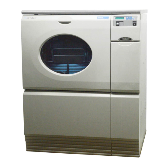
Page 31: Figure 3-1. Processor With Countertop (Option)
Countertop Control Panel (Option) Side Enclosure Panel(s) Window Chamber Door Service Access Panel Bag-in-a-Box Base Compartment Figure 3-1. Processor With Countertop (Option) Identification Nameplate Base Figure 3-2. Processor Without Countertop (Option) 920011-649 Operator Manual Component Identification... -
Page 32: Chamber
3.1.5 Chamber See Figure 3-3. The high-quality stainless-steel chamber is insulated to reduce heat loss and noise level. Four manifold connectors are provided at the back of the chamber: one is the hot water inlet to the Reliance ™ Chemical Delivery System, two are connectors for the pressure sensors and one is for the endoscope processing support. -
Page 33: Figure 3-3. Chamber And Service Access Interior
Pressure Sensor Connector For Pressure Sensor Connector For " " " " Control Handle Boot Control Handle Boot Hot Water Inlet (to Reliance CDS) Interior Main Manifold Fluorescent Connector Light (to Endoscope Processing Support) Sump 0.2 µm Bacterial- Retentive Removable Filter Debris Screen REF:#MB30_PP_51_2... -
Page 34: Endoscope Processing Support
(e.g., small diameters and no light guide cables). A dedicated chemical indicator clip on control handle boot "A" is designed to firmly hold the STERIS chemical indicator validated for use with the Reliance EPS Endoscope Processing System in place during the ™... -
Page 35: Figure 3-4. Endoscope Processing Support
Detail A Control Handle " " Boot Insertion Tube Diameter Template Slots Control Handle " " Boot Reliance CDS Accessory Basket Chemical Delivery Chemical System Universal Indicator Cord Port Clip Control Handle Boot Plug (x Two) Insertion Tube Sleeves (x Six) Large Mesh Fluid Flow Basket... -
Page 36: Control
3.3 Control IMPORTANT: Become familiar with all control locations and functions before operating the Reliance EPS (see Figure 3-5). The Reliance EPS Processor is equipped with a microprocessor control system. The control system monitors and automatically CAUTION – POSSIBLE EQUIPMENT controls all cycle operations and functions. -
Page 37: Figure 3-5. Control Panel
Figure 3-5. Control Panel 920011-649 Operator Manual Component Identification... -
Page 38: Supervisor Mode
3.3.2 Supervisor Mode The Supervisor mode section of the control panel is accessed behind the control panel cover. Once the cover is removed, this section of the control panel allows the supervisor to modify preprogrammed parameters within a range of factory set values such as date and time, and to disable/enable printer functions. -
Page 39: Display Screen
6-minute exposure segment). For ordering information, contact STERIS. IMPORTANT: Review the information provided in the Reliance dry chemistry package insert prior to use. Contact STERIS with any questions regarding the safe and proper use of Reliance dry chemistry. 3-10 920011-649... -
Page 40: Steris Chemical Indicator
Refer to the bottle label and product insert for details on storage conditions, expiration date, handling, use instructions and Safety Precautions. NOTE: From this point forward in this manual the "STERIS chemical indicator validated for use with the Reliance EPS" will be referred to as "chemical indicator". -
Page 41: Dual Pre-Filter And Pressure Regulator Assembly (Required Accessory)
3.7 Dual Pre-Filter and See Figure 3-8. Pressure Regulator The Dual Pre-Filter and Pressure Regulator Assembly (required Assembly (Required accessory) is designed to help reduce the particulate and microbial Accessory) load on the final 0.2 μm bacterial-retentive filter. This required accessory includes: •... -
Page 42: Endoscope Overview And Vocabulary
Reliance EPS. 3.8.1 Endoscope Vocabulary The following is the list of terms used by STERIS and their possible List equivalents: Term used by STERIS Can also be referred to as... -
Page 43: Endoscope With Biopsy/Suction System
3.8.2 Endoscope With Biopsy/ See Figures 3-9 and 3-10. Suction System Channeled flexible endoscopes have at a minimum a suction/biopsy channel. The suction/biopsy channel may be accessed at three ports: the suction barb (which may be on the control handle or the light guide);... -
Page 44: Endoscope With Air/Water System
3.8.3 Endoscope With Air/ See Figure 3-10. Water System Flexible gastrointestinal (GI) endoscopes have an air/water system in addition to a biopsy/suction system. The air/water system consists of two channels that begin at the air/water port on the light guide connector. - Page 45 3-16 920011-649 Operator Manual Component Identification...
-
Page 46: Processing Instructions
Endoscopes with additional channels that do not have channel openings on the control handle must be processed with the aid of a STERIS Flow Unit. Refer to the Endoscope Quick Reference Guide and the Quick Reference Wall Chart - Flow Units for details. -
Page 47: Optional Automated Leak Test Assembly
INSIDE PRESSURIZED CONTROL HANDLE BOOT Air/Water Valve Port Suction Biopsy Valve Port Port Auxiliary OUTSIDE PRESSURIZED Water Inlet CONTROL HANDLE BOOT AUXILIARY WATER INLET Air/Water Port Air/Pipe Suction Barb Figure 4-1. Solution Flow Schematic 920-013-571 4.1.2 Optional Automated The automated leak test feature offered on the Reliance ™... - Page 48 IMPORTANT: The list of devices given in the Endoscope Quick Reference Guide may not be all-inclusive but reflects the complete information available to STERIS Corporation at the date of its publication. Medical devices can be added to the list without further notice.
- Page 49 WARNING – INEFFECTIVE STERIS CORP PROCESS HAZARD: • Follow COPYRIGHT (C) 2011 applicable instructions provided by the then: endoscope manufacturer for preparing endoscope and READY accessories for immersion. MM-DD-YY HH:MM XM Failure to do so may result in damage to endoscope and/ and printer records, for example: or ineffective processing.
-
Page 50: Figure 4-2. Large Mesh Basket And Accessory Basket
d. Place cover on accessory basket and push downward to lock. e. Insert basket in holder located on back section of endoscope processing support. If processing dilators and bougies, follow instructions in Endoscope Quick Reference Guide for Flow Unit 5. Detail A Wire Mesh Cover Valve Irrigator... -
Page 51: Figure 4-3. Accessory Basket Insertion From Control Side
NOTE: If accessory basket has been mounted to be accessed from right side of Reliance EPS Processor (see Figure 4-3, Detail A), push accessory basket on guiding rails from right side of endoscope processing support toward center of support. Insert handle into locking slot to prevent accessory basket from sliding out (see Figure 4-3, Detail B). -
Page 52: Figure 4-4. Carefully Insert Insertion Tube In Template Slot
10. Determine if endoscope requires an insertion tube sleeve as follows (see Figures 4-4 and 4-5): CAUTION–POSSIBLEEQUIPMENT NOTE: Insertion tube should fit easily with no force applied. DAMAGE: When using insertion tube sleeve, ensure that sleeve • Locate three diameter template slots in front of endoscope handle pushed down. -
Page 53: Figure 4-5. Insertion Tube Sleeves For Small Diameter Insertion Tubes
11. If using insertion tube sleeve labeled with a RED dot or a proceed as follows (see Figure 4-5): BLUE dot, WARNING – INEFFECTIVE a. Insert insertion tube sleeve into control handle boot opening, PROCESS HAZARD: When as shown in Figure 4-5. Verify insertion tube sleeve handle is placing endoscope pushed down. -
Page 54: Figure 4-6. Insert Insertion Tube Into Control Handle Boot Opening
b. Carefully feed distal end of insertion tube into insertion tube slide (see Figures 4-6 and 4-7). Feed entire insertion tube CAUTION–POSSIBLE EQUIPMENT into slide. DAMAGE: Do not place light guide/ultrasound connectors IMPORTANT: Hold insertion tube near control handle boot on their cables or damage opening to ease insertion and prevent damage caused by may result. -
Page 55: Figure 4-9. Feeding Distal Tip Into Sleeve
b. Carefully feed distal tip of insertion tube into split insertion tube sleeve (see Figure 4-9). c. When split insertion tube sleeve is located further up insertion tube, away from distal tip bigger end, close sleeve carefully around insertion tube (see Figure 4-10). d. -
Page 56: Figure 4-11. Coil Light Guide Cable And Connect Flow Units
While control handle is resting on control handle boot frame, secure split insertion tube sleeve into control handle boot opening (see Figure 4-6). Verify split insertion tube sleeve handle is pushed down. Insertion tube must be inserted over sleeve handle to avoid possible damage (see Figure 4-10). -
Page 57: Figure 4-12. Plug To Process Only One Endoscope
18. If processing endoscopes without a light guide cable (model numbers are indicated in Endoscope Quick Reference Guide), insert a control handle boot plug into universal cord port of control handle boot (see Figure 4-13). 19. Before closing control handle boot “A”, ensure light guide cable from control handle boot “B”... -
Page 58: General Processing Guidelines
WARNING – INEFFECTIVE DOUBLE endoscope processing cycle with washing phase using PROCESS HAZARD: Before Reliance dry chemistry and STERIS chemical indicator. See starting a cycle, ensure rotary 4.2, G , through S ECTION ENERAL... -
Page 59: Figure 4-14. Insertion Tube Sleeve
Insertion Tube Sleeve With a Blue Dot Identification Flaps Figure 4-14. Insertion Tube Sleeve Test Cord Universal Cord Port Figure 4-15. Test Cord 4-14 920011-649 Operator Manual Processing Instructions... -
Page 60: Preparation
Open Reliance CDS. h. Insert one Reliance dry chemistry container (refer to Reliance dry chemistry package insert). Close Reliance CDS and latch. Insert one STERIS chemical indicator strip in clip on control handle boot "A" (see S 4.6, I STERIS... -
Page 61: Figure 4-16. Automated Leak Test Hose Assembly (Fujifilm Shown)
(see Figure 4-18). water to enter hoses. Inspect leak test hose assemblies for 6. Insert Reliance dry chemistry container and STERIS presence of water prior to chemical indicator strip in endoscope processing support processing a cycle. Water in (see 4.5,... -
Page 62: Figure 4-17. Connect Quick Connect Extremity Of Leak Test Hose(S) To Flexible Connection(S)
7. Push endoscope processing support back into chamber. 8. Close door. PROCESSOR IS NOW READY TO PROCESS A CYCLE. Flexible Connection Leak Test Hose Quick Connect Extremity Quick Connect Locking Sleeve Figure 4-17. Connect Quick Connect Extremity of Leak Test Hose(s) to Flexible Connection(s) Endoscope Leak Test Port... -
Page 63: Pentax Leak Test Adapter For I10C Series
After cycle is completed, disconnect extremity of leak test hose(s) from endoscope leak test port(s) (see Figure 4-18). After cycle is completed, when you need to disconnect quick connect extremity of leak test hose(s) from flexible connection(s), proceed as follows: 1. -
Page 64: Status
4.4.4 Status See Figure 4-20. When an automated leak test is performed and leak test hose(s) is (are) connected, no further action is required. The SINGLE or DOUBLE CAUTION–POSSIBLEEQUIPMENT cycle runs and the following printout is printed immediately after the leak test sequence: DAMAGE: Remove... - Page 65 ========================= HH:MM:SS XM MM-DD-YY ========================= FAULT 53 ========================= NOTE: If an error message is displayed at any time during cycle, refer to S 7, T , for possible causes and solutions. ECTION ROUBLESHOOTING Alarm can be silenced by pressing ALARM REPLY touch pad. 4-20 920011-649 Operator Manual...
-
Page 66: Figure 4-20. Leak Test Hoses Connections Flowchart
DETECTION BY CONTROL Leak Test Hose(s) Connected ? ▼ ▼ ▼ No: “Audible Signal” * ▼ ▼ ▼ Ignore Stop Touch Pad ▼ Draining ▼ ▼ ▼ ▼ No Further Action Required Resume Cancel ▼ ▼ ▼ ▼ Leak Test No Leak Test Go to Step 1 of S 4.4.4,... -
Page 67: Audible Signal
4.4.5 Audible Signal See Figure 4-20. When an automated leak test is performed, there may be an audible signal to notify the operator the control detected a disconnected or a non-connected hose while a SINGLE or DOUBLE cycle is running. The audible signal can be either ignored or acknowledged. -
Page 68: Self-Diagnostic
4.4.6 Self-Diagnostic The leak test self-diagnostic is available to the user and is to be performed without any endoscope to verify the integrity of the system. The leak test self-diagnostic lasts approximately 90 seconds. Leak test self-diagnostic can be performed with either the CAUTION–POSSIBLEEQUIPMENT door opened or closed. - Page 69 5. In Idle mode (when READY is shown on display), activate leak test self-diagnostic by pressing START touch pad four times. A message is displayed to indicate self-diagnostic is running: LEAK TEST SELF-DIAGNOSTIC The following printout is printed at the end of the leak test self- diagnostic: ======================== HH:MM:SS XM...
-
Page 70: Installing Reliance Dry Chemistry Container
• Before starting a cycle, ensure to verify Reliance dry chemistry container's Figure 4-22. Reliance Dry Chemistry expiration date and STERIS chemical indicator bottle's expiration date are valid. If expiration date is not valid, use a new Reliance dry... -
Page 71: Inserting Steris Chemical Indicator Strip
4.6 I nserting STERIS 1. Refer to chemical indicator package insert for directions for use, Chemical Indicator Strip interpretation of results, storage and disposal information. 2. Place chemical indicator strip in chemical indicator clip found on control handle boot "A" (see Figure 4-23). Ensure indicator pad is WARNING –... -
Page 72: Pre-Processing Checklist
4.7 Pre-Processing The following conditions are necessary to achieve successful Checklist processing of the endoscopes and accessory types listed in the Endoscope Quick Reference Guide. – ENDOSCOPE PREPARATION – Endoscope and accessories were: inspected and found to be in proper working order; �... -
Page 73: Processing Cycle
Reliance CDS (see 4.5, I ECTION NSTALLING ELIANCE HEMISTRY ONTAINER STERIS chemical indicator bottle's expiration date is valid and � chemical indicator strip is placed in the clip on control handle boot "A" (see 4.6, I STERIS C ECTION... -
Page 74: Optional Testing Prior To Starting Cycle
4.8.1 Optional Testing Prior NOTE: The following steps may be performed if the Reliance EPS to Starting Cycle Processor is equipped with an optional Automated Leak Test Assembly. IMPORTANT: The following steps are optional and only used as a method of testing the endoscope(s) status prior to the initiation of a standard endoscope processing cycle. -
Page 75: Starting Cycle
8. In Idle mode (when READY is shown again on display), press START touch pad four times. The following printout is printed at end of testing: ======================== HH:MM:SS XM MM-DD-YY ======================== LEAK TEST SELF-DIAGNOSTIC = ======================== TEST 1: XXXX TEST 2: XXXX ======================== XXXX shows "PASS"... - Page 76 4. To process one endoscope in a cycle with a washing phase, press SINGLE touch pad once. Display shows: SINGLE WITH WASHING ...or... To process one endoscope in a cycle without a washing phase (high level disinfection phase only), press SINGLE touch pad twice.
- Page 77 NOTE: When using bar code reader, note the following: 1) Customizable STERIS bar code lists are included in instructions for "Bar Code Reader Installation" (P920011- 654). 2) Alphanumeric bar codes present on devices or identification cards (with a maximum of 20 alphanumeric characters) can also be used with bar code reader.
-
Page 78: Endoscope Detection
Once filling is completed, displays shows: Countdown to OPERATING Cycle Completion MMM MIN NOTE: After selecting cycle, if START touch pad is not pressed within ten seconds, display returns to READY mode. 4.8.3 Endoscope Detection If present and selected in Miscellaneous Values menu of Supervisor mode (refer to S 5.2.3, S ECTION... -
Page 79: Low Chemical Warning
4.8.4 Low Chemical Warning This option is used to warn operator when level of chemical in Bag- in-a-Box indicated in display message is getting low. It should prevent having a chemical empty alarm during a cycle. Low chemical warning is enabled in Miscellaneous Values menu of Supervisor mode by setting CHEMICAL WARNING option to YES (refer to S 5.2.3, S... -
Page 80: Monitoring Cycle
4.8.5 Monitoring Cycle During cycle, information is printed about cycle in progress. See Figures 4-24 and 4-25 for typical sample printout. At any time during cycle, operator can display temperature and pressure inside control handle boots by pressing touch pad of cycle in process (SINGLE or DOUBLE). -
Page 81: Figure 4-24. Typical Cycle Printout
====================== ====================== COMPLETED HH:MM:SS XM CYCLE – SINGLE PHASE TIME TOTAL CYCLE HH:MM:SS WITH WASHING ====================== ====================== HH:MM:SS XM MAXIMUM CYCLE START HH:MM:SS XM WASH FILLING TIME MM:SS CYCLE DATE MM-DD-YY WATER TYPE CYCLE NUMBER XXXXXXXX TEMPERATURE XX.X C STOP PRESSED HH:MM:SS XM UNIT NUMBER 36XXXXXXXX RECIRC. -
Page 82: Figure 4-25. Typical Cycle Printout - Details
DISINFECTION: Duration of exposure to high level disinfection solution. In question DID CI PASS YES/NO; Identification PROCEDURE CI = STERIS chemical indicator number of procedure. RECIRC. TIME: Duration of solution/air recirculation. PHYSICIAN ID: Physician's code and name. COMPLETED: Time at which cycle... -
Page 83: Completing Cycle
4.8.6 Completing Cycle 1. After four minutes of air purge (adjustable from 4 to 30 minutes in Supervisor mode), buzzer sounds and display shows: CYCLE COMPLETE PRESS STOP It is now possible to unload processor or let air purge phase continue. -
Page 84: Process Verification And Unloading Procedure
(see Figures 4-24 and 4- PROCESS HAZARD: 25). • Correct function of the • Process verification is achieved through use of a STERIS system is only ensured chemical indicator and fresh dry chemistry container detection after any diagnosed errors meter. -
Page 85: Verification 1 - Parametric Controls
4.9.1 VERIFICATION 1 – NOTE: For a 50 Hz processor, refer to Operator Manual Information Parametric Controls Supplement (P920501-322) for specific information. After the processing cycle is completed: 1. Verify display shows: CYCLE COMPLETE READY TO UNLOAD Printer records a complete cycle printout (see Figures 4-24 and 4-25 to view an example of a typical printout). - Page 86 See Troubleshooting Chemical Indicator for Reliance EPS section for procedure. A STERIS chemical indicator validated for use with the Reliance EPS • If chemical indicator strip is used as an independent monitor of the Reliance EPS Cycle. The exhibits incomplete color...
-
Page 87: Water Sampling Test
7. If used, remove control handle boot plug and insertion tube sleeve. Store on their dedicated holders on endoscope processing support. IMPORTANT: After processing, use immediately or store and use per facility department policy and procedures. The "Multi- society Guideline for Reprocessing Flexible Gastrointestinal Endoscopes"... - Page 88 TEST then: OPEN DOOR 6. When chamber door is opened, operator can take a sample of water from sump. Then display shows: CLOSE DOOR 7. Close chamber door. Display shows: PRESS START 8. Press START touch pad to resume cycle. 9.
-
Page 89: Post-Processing Checklist
4.11 Post-Processing The following conditions are necessary to achieve successful Checklist processing of the endoscopes and accessory types listed in the Endoscope Quick Reference Guide: Cycle is complete and printout "READY TO UNLOAD" message � verified (see 4.9.1, VERIFICATION 1 – P ECTION ARAMETRIC ONTROLS... - Page 90 alternating with: WARNING – INEFFECTIVE PROCESS HAZARD: STOP PRESSED • Correct function CYCLE DELAYED system is only ensured after any diagnosed errors have and printer records: been found, corrected and a successful processing cycle ========================== has been completed. CYCLE PAUSE HH:MM:SS XM •...
- Page 91 alternating with: PLEASE WAIT MMM MIN then: WARNING CYCLE CANCELLED then: If Disinfection CHEM CONTAINER Solution Was Generated Within MUST BE REPLACED Processor If Disinfection CHEM CONTAINER Solution Was Not Generated Within STILL USABLE Processor then: LOAD NOT H-L DISINFECTED and printer records: ****************************************** WARNING...
-
Page 92: Responding To A Fault
4.13 Responding to a Fault messages warn operator if the processor is experiencing an Fault abnormal condition. Fault conditions can be caused by failure of utility supplies or by processor components. Refer to S 7.2, F , for a detailed listing of fault ECTION AULT HART... - Page 93 Printer records: ========================= CYCLE RESUME HH:MM:SS XM ========================= If FAULT alarm occurs during HLD GENERATION DISINFECTION phase, the cycle must be aborted (refer to 7, T ), display shows: ECTION ROUBLESHOOTING STOP TO CANCEL Press STOP touch pad to abort. Processor performs Abort sequence three times: chamber is filled with filtered tap water and water is recirculated and then drained (approximately 15 minutes total).
-
Page 94: Maintenance Due Faults
========================== CYCLE CANCEL HH:MM:SS: XX ========================== IMPORTANT: If a recurring alarm occurs that prevents the Abort sequence from being completed, call STERIS. 4.13.2 Maintenance Due There are four MAINTENANCE DUE alarms indicating when specific Faults routine maintenance needs to be performed on the processor. -
Page 95: Shutdown
4.14 Shutdown There is no Shutdown mode on the Reliance EPS Processor. The processor should remain ON at all times except when performing maintenance or repairs. WARNING – ELECTRIC SHOCK If it is necessary to turn OFF the processor, wait until cycle is AND/OR BURN HAZARD:... - Page 96 then: WARNING CYCLE CANCELLED then: If Disinfection CHEM CONTAINER Solution Was Generated Within MUST BE REPLACED Processor If Disinfection CHEM CONTAINER Solution Was Not Generated Within STILL USABLE Processor then: LOAD NOT H-L DISINFECTED and printer records: ****************************************** WARNING LOAD NOT H-L DISINFECTED ****************************************** When Abort sequence is completed, display shows:...
-
Page 97: Unlocking Processor Door During A Power Failure
4.15.2 Unlocking Processor On occasion it may be necessary to manually open the Reliance EPS Door During a Power Failure Processor chamber door, for example during a prolonged power failure. Operator should remove flexible endoscopes accessories. Thoroughly rinse endoscopes, accessories and Flow Units. -
Page 98: Dry Chemistry Container Disposal
Door Manual Safety Latch Control Panel Cover Bag-in-a-Box Compartment Door Base Figure 4-26. Door Manual Safety Latch 4.16 Dry Chemistry If Reliance dry chemistry container is leaking, damaged or expired, Container Disposal follow disposal instructions provided in the dry chemistry package insert. -
Page 99: Disposing Of Expired Dry Chemistry
4.17 Disposing of To dispose of expired Reliance dry chemistry, run a DOUBLE Expired Dry Chemistry endoscope processing cycle without washing phase, and without endoscopes. See S 4.2, G , through S ECTION ENERAL ROCESSING UIDELINES ECTION 4.7, P , for additional information. ROCESSING HECKLIST WARNING –... -
Page 100: Figure 4-28. Test Cord
5. Insert test cord in insertion tube sleeve and in flaps of universal cord port of control handle boots "A" and "B" (see Figure 4-28). Let test cord extend approximately 51 mm (2") outside of universal cord port (see Figure 4-28). Close control handle boots and latch. 6. - Page 101 and printer message is: ========================= HH:MM:SS XM MM-DD-YY ========================= FAULT 38 ========================= 13. Press ALARM REPLY touch pad to silence audible alarm. Display shows: STOP TO CANCEL 14. Press STOP touch pad to abort cycle. Processor performs Abort sequence three times: chamber is filled with filtered tap water and water is recirculated and then drained (approximately 15 minutes total).
-
Page 102: Cycle And Control Value Programming
CYCLE AND CONTROL VALUE PROGRAMMING IMPORTANT: A listing of the Safety Precautions to be observed when operating and servicing this processor can be found in S 1 of this manual. Do not operate the equipment until you have become ECTION familiar with this information. -
Page 103: Table 5-1. Reliance Eps Endoscope Processing System - Cycle Description Chart
Table 5-1. Reliance EPS Endoscope Processing System – Cycle Description Chart – RELIANCE EPS CYCLE SINGLE OR DOUBLE OPTIONAL PHASES WITH WASHING REPEAT WASHING Sub-Phase WASH RINSE WASH RINSE RINSE 1 RINSE 2 AIR PURGE Water type Temperature set point... -
Page 104: Supervisor Mode
5.2 Supervisor Mode Supervisor mode touch pads are hidden behind plastic control cover to limit access. Supervisor mode includes following menus: • Change Cycle Values – Includes displays to modify phase values (see Table 5-1, Cycle Description Chart, for adjustable phase values). -
Page 105: Changing Cycle Values
STERIS CORP COPYRIGHT (C) 2011 then: READY MM-DD-YY HH:MM XM 3. Press CHANGE VALUES touch pad to enter Supervisor mode. Display shows for example: SCROLL TO MODIFY SINGLE __ blinking and printer records: =========================== HH:MM:SS XM MM-DD-YY =========================== SUPERVISOR MODE =========================== 5.2.2 Changing Cycle Values... - Page 106 3. Press ENTER touch pad to confirm selection. Display moves on to WASH segment of selected cycle. Display shows, for example: WASH RECIRC MM:SS __ blinking and printer records, for example: ========================== HH:MM:SS XM MM-DD-YY ========================== MODIFY: SINGLE ========================== 4. Press SCROLL arrows (left or right) to change time value of WASH 1 segment (adjustable from five to ten minutes).
- Page 107 and printer records, for example: ========================== HH:MM:SS XM MM-DD-YY ========================== MODIFY : SINGLE ========================== 7. Press SCROLL arrows (left or right) to change time value of AIR PURGE phase (adjustable from 4 to 30 minutes). IMPORTANT: A decrease in air purge efficiency may be caused by a clogged HEPA filter or pre-filter.
- Page 108 If YES is selected, printer records values of cycle just modified, for example: =========================== HH:MM:SS XM MM-DD-YY =========================== CYCLE - SINGLE WITH WASHING =========================== WASH WATER TYPE TEMPERATURE 48.0 C RECIRC. TIME 05:00 CHEMICAL KLENZYME CONCENTR. 2 mL/L RINSE WATER TYPE RECIRC.
-
Page 109: Setting Miscellaneous Values
5.2.3 Setting Miscellaneous Miscellaneous menu allows supervisor to set time and date, to Values enable or disable printer functions or to print cycle values during cycle. Miscellaneous menu includes the following settings: MENU FUNCTION To set programmed language selection. Language To set current time of day. - Page 110 2. Press SCROLL arrows (up or down) until MISCELLANEOUS appears. 3. Press ENTER touch pad to confirm selection. Display shows: LANGUAGE ENGLISH __ blinking 4. Press SCROLL arrows (up or down) to scroll through available languages for display messages and printouts. 5.
- Page 111 10. Press SCROLL arrows (up or down) to enable (YES) or disable (NO) bar code reader. If NO is selected, display goes to Step 21. 11. Press ENTER touch pad to confirm setting. Display shows: OPERATOR ID __ blinking 12. Operator ID function allows operator to scan a bar code to identify processor operator.
- Page 112 19. Press ENTER touch pad to confirm setting. Display shows: PHYSICIAN ID __ blinking 20. Physician ID function allows operator to scan a bar code to identify physician who used endoscope to be processed. Physician ID is recorded on cycle printout. Press SCROLL arrows (up or down) to enable (YES) or disable (NO) optional Physician ID function.
- Page 113 25. Press ENTER touch pad to confirm setting. Display shows: REPEAT WASHING __ blinking 26. REPEAT WASHING screen allows supervisor to choose if WASHING phase (WASH segment followed by RINSE segment) is to be performed once or twice during SINGLE endoscope processing cycle WITH WASHING or DOUBLE endoscope processing cycle WITH WASHING (see Table 5-1, Cycle Description Chart).
- Page 114 31. Press ENTER touch pad to confirm setting. Display shows: AUTO D-SHORT __ blinking 32. AUTOMATIC D-SHORT screen allows operator to activate or deactivate second D-SHORT starting after 36 hours of inactivity. Press SCROLL arrows (up or down) to enable (YES) or disable (NO) AUTOMATIC D-SHORT feature.
- Page 115 38. MULTIPLE PRINTOUTS feature is set to YES to allow operator to generate more than one printout after each cycle. Press SCROLL arrows (up or down) to enable (YES) or disable (NO) MULTIPLE PRINTOUTS feature. Display shows: CYCLE PRINTS PER ENDOSCOPE X After each cycle in progress, number of cycle printouts requested is generated for each endoscope.
- Page 116 and printer records, for example: ======================== HH:MM:SS XM MM-DD-YY ======================== SUPERVISOR MODE CONFIGURATION ======================== BAR CODE READER: OPERATOR ID: PATIENT ID: DEVICE ID: PROCEDURE ID: PHYSICIAN ID: 0.2 μm FILTER REMAINING DAYS: WASHING SELECT: REPEAT WASHING: WATER SAMPLING: CHEMICAL WARNING: AUTOMATIC D-SHORT LEAK TEST DUPLICATE PRINTOUT:...
-
Page 117: Performing Bar Code Test And Programming Operator And Physician Id Lists
47. Press ENTER touch pad to confirm selection. Display shows, for example: SINGLE PRINTING and printer records, for example: =========================== HH:MM:SS XM MM-DD-YY =========================== CYCLE - SINGLE WITH WASHING =========================== WASH WATER TYPE TEMPERATURE XX.X C RECIRC. TIME MM:SS CHEMICAL KLENZYME CONCENT. -
Page 118: Routine Maintenance
Maintenance Manual (P764333-736) for complete replacement Maintenance Manual parts list. preventive maintenance is done by the Customer. • Repairs and adjustments to this equipment must be made only by STERIS or STERIS- trained service personnel. Nonroutine maintenance performed unqualified... -
Page 119: Routine Maintenance
6.2 Routine Procedures included in this Routine Maintenance Guide should be Maintenance carried out only by operators who have received proper STERIS training. Refer appropriate sections containing detailed instructions following this table for complete procedures. Table 6-1. Routine Maintenance Guide Recommended frequency of inspection is indicated in the right column. -
Page 120: Debris Screen
4 X/year 6.10.2). ECTION *Contact STERIS for this service. Service charges may be incurred. Consult your warranty for details. 6.3 Debris Screen After last cycle of the day, remove debris screen and clean under running water. Replace in bottom of chamber. Always clean debris screen while it is still wet, before debris dries. -
Page 121: D-Short Cycle
No cleaner or Reliance dry chemistry is used for this cycle. STERIS recommends a D-SHORT cycle be processed at end of each workday or at the end of the workday each Monday, Wednesday and Friday. D-SHORT cycle is approximately 45 minutes long. - Page 122 7. Close chamber door. 8. Press DECONTAM touch pad once. Display shows: D-SHORT PRESS START IMPORTANT: If a D-SHORT cycle has not been completed within 54 hours, processor control will be automatically locked, i.e. no SINGLE or DOUBLE endoscope processing cycle can be started until a D-LONG cycle is performed (see S 6.11, D-LONG ECTION...
-
Page 123: Figure 6-1. D-Short Sample Printout
IMPORTANT: If door is not opened and no touch pad or pushbutton is pressed once D-SHORT cycle is completed (during a weekend for example), a second D-SHORT cycle automatically starts after 36 hours so the processor is ready to use on Monday. AUTOMATIC D-SHORT feature is set in Miscellaneous menu 5.2.3, S ). -
Page 124: Surfaces Of Processor
6.6 Surfaces of The following cleaning procedures should be performed once per week: Processor 1. Clean front of processor using a general purpose cleaner (nonabrasive). Rinse with tap water and dry with a lint-free cloth. 2. Wipe all inside and outside plastic surfaces or painted surfaces CAUTION –... -
Page 125: Replacing Bag-In-A-Box Container
6.8 Replacing Bag-in-a- NOTE: It is possible to change a Bag-in-a-Box container while a cycle Box Container is in progress. Processor is self-priming. When Bag-in-a-Box container is empty, display shows: FAULT 08 (OR 09)* CYCLE DELAYED *Fault 08 = CIP200, Fault 09 = Klenzyme alternating with: SEE FAULT CHART CYCLE DELAYED... - Page 126 See Figures 6-3 and 6-4. Wearing appropriate Personal Protective Equipment (PPE), replace WARNING – PERSONAL INJURY Bag-in-a-Box container as follows: AND/OR EQUIPMENT DAMAGE 1. Open Bag-in-a-Box compartment door. Raise locking plate to HAZARD: Bag-in-a-Box release feed line connector. compartment door can support 2.
-
Page 127: Figure 6-3. Bag-In-A-Box Compartment
CAUTION – POSSIBLE EQUIPMENT DAMAGE: To ensure cleanliness Upper Shelf (Klenzyme) during operation and to avoid damage to zinc-coated steel, wipe any cleaner spills or drippage inside Bag-in-a-Box Middle Shelf compartment. Clean (CIP 200) surface that might have been in contact with any cleaner inside Bag-in-a-Box compartment. -
Page 128: Figure 6-4. Changing Bag-In-A-Box Container
Detail B Detail A Bag-in-a-Box Container Exterior Groove Box (and Flap) With Fitting in Exterior Groove Snap-On Closure Interior Groove Feed Line Snap-On Connector Closure Bag-in-a-Box Drip Tray Fitting Container Drip Tray Locking Plate Fitting Detail C Bag-in-a-Box Container Locking Plate Locking Pin Feed Line Connector Drip Tray Fitting... -
Page 129: Changing Printer Ribbon And Paper Roll
Keep printer User's Manual in an easily accessible place along with other documentation for Reliance EPS. IMPORTANT: The use of STERIS paper and ribbon cartridge is recommended. Using non-STERIS paper and cartridge can result in defects or other problems and can void the warranty. For information... -
Page 130: Changing Pre-Filters
6.10 Changing Pre- Filters 6.10.1 Dual Pre-Filter and To evaluate how frequently filter cartridges must be changed in your Pressure Regulator Assembly facility, review last ten cycle printouts. An increase in filling time indicates cartridges are clogged and need to be changed. Change Cartridges (Required filter cartridge "A"... -
Page 131: Figure 6-6. Changing Dual Pre-Filter And Pressure Regulator Assembly Cartridges
Manual Ball Valve Lever Purge Buttons Housing Body O-Ring Manual Ball Valve Lever O-Ring Multi-Layer Depth Media Filter Cartridge Pressure Gauge Dual-Layer Absolute Membrane Filter Cartridge Spanner Wrench Filter Bowl Figure 6-6. Changing Dual Pre-Filter and Pressure Regulator Assembly Cartridges (Required Accessory) 6-14 920011-649 Operator Manual... -
Page 132: Μm Bacterial-Retentive Filter Cartridge
6.10.2 0.2 µm Bacterial- See Figure 6-7. Retentive Filter Cartridge 0.2 μm bacterial-retentive filter must be replaced at least every 90 days (default, adjustable from 0 to 90 days in Supervisor mode; WARNING – PERSONAL INJURY refer to S ). This time 5.2.3, S ECTION ETTING... - Page 133 Housing Cap Venting Connection Turn Counterclockwise Housing Cap Figure 6-7. Replacing 0.2 µm Bacterial-Retentive Filter Cartridge 6-16 920011-649 Operator Manual Routine Maintenance...
-
Page 134: D-Long Cycle
6.11 D-LONG Cycle Thirty hours after last decontamination cycle (D-SHORT or D-LONG) has been processed, display shows: D-SHORT REQUIRED XX HOURS LEFT -- or -- D-SHORT REQUIRED XX MINUTES LEFT If a decontamination cycle is not completed before countdown reminder reaches "0", control is locked until a D-LONG cycle is performed. - Page 135 9. Press START touch pad. Display shows: REMOVE ALL WARNING – CHEMICAL BURN ENDOSCOPES AND/OR EYE INJURY HAZARD: alternating with: CIP 200 Acid-Based Process Research Cleaner PRESS START corrosive cause adverse effects to exposed WHEN READY tissues. Do not get in eyes, on 10.
-
Page 136: Rotary Spray Arm Assembly
6.12 Rotary Spray Arm See Figure 6-8. Assembly 1. Clean processor chamber rotary spray arm assembly as follows: a. At top of chamber, loosen thumb screw from rotary spray arm assembly. b. Remove and lower rotary spray arm assembly. WARNING – ELECTRIC SHOCK c. -
Page 137: Lubrication Of Leak Test Hose Assembly O-Ring
6.13 Lubrication of See Figure 6-9. Leak Test Hose 1. Leak test hose assembly maintenance kit (P117034-898) Assembly O-Ring contains grease and lubrication tool. 2. Apply a small amount of grease on extremity of lubrication tool. 3. Gently slide extremity of tool on surface of endoscope connection O-ring to lubricate. -
Page 138: Troubleshooting
7.1), or the Fault Chart (S 7.2), or if a problem ECTION ECTION STERIS-trained service occurs that is not described on either chart, please call STERIS. personnel. Nonroutine maintenance performed by NEVER PERMIT UNQUALIFIED PERSONS TO SERVICE THE unqualified personnel or RELIANCE EPS PROCESSOR. -
Page 139: Troubleshooting Chart
ECTION 3. If condition reoccurs, call STERIS.* 7. Vapor, mist or unusual odor Damaged door gasket and/or damaged door interlocks, call STERIS.* emanating from chamber. 8. Heat loss from chamber. Hot air Damaged door gasket and/or door interlocks, call STERIS.* escaping from door during air purge phase. - Page 140 MUST REPROCESSED THROUGH A COMPLETE RELIANCE EPS CYCLE (refer to S ECTION d. Call STERIS.* 4. Plastic plugs within Reliance CDS are missing. a. Remove any endoscopes and accessories present in control handle boot(s) and endoscope processing support baskets and accessory pegs.
- Page 141 ECTION 2. If Flow Unit is disconnected at end of repeated cycle, inspect Flow Unit and Flow Units ports for obvious damage, call STERIS.* 12. Abnormal quantity of water in 1. May be a normal situation if door is opened immediately after an endoscope channels ends after air purge.
-
Page 142: Fault Chart
If situation reoccurs, see Step 5. 5. Building hot water supply pressure is too low (refer to equipment drawing [920-011-656]). Call STERIS.* 6. Other possible causes: Defective hot water fill valves. - Page 143 FAULT POSSIBLE CAUSE AND CORRECTION Alarm sounds, and display shows: SUMP OVERFLOW Try to resume cycle by pressing START touch pad. If FAULT 04 situation reoccurs, call STERIS.* CYCLE DELAYED alternating with: SEE FAULT CHART CYCLE DELAYED Printout message: HH:MM:SS XM...
- Page 144 (PPE), clean Bag-in-a-Box injection system, and reinstall Printout message: Bag-in-a-Box container (refer to 6.8). ECTION HH:MM:SS XM MM-DD-YY 3. Defective cleaner pressure switch, call STERIS.* --------------------------------------- FAULT 08 Alarm sounds, and display shows: KLENZYME EMPTY 1. Klenzyme Enzymatic Presoak and Cleaner Bag-in-a-Box FAULT 09 container is empty.
- Page 145 FAULT POSSIBLE CAUSE AND CORRECTION Alarm sounds, and display shows: DOOR OPEN 1. If door opens during cycle, call STERIS.* FAULT 11 2. If door is closed, resume cycle by pressing START touch CYCLE DELAYED pad. If situation reoccurs, call STERIS.*...
- Page 146 FAULT 18 – Not used. Alarm sounds, and display shows: BOARD RTD OVERHEAT Try to resume cycle by pressing START touch pad. If FAULT 19 situation reoccurs, call STERIS.* CYCLE DELAYED alternating with: SEE FAULT CHART CYCLE DELAYED Printout message:...
- Page 147 2. Air purge pre-filter needs changing, call STERIS.* SEE FAULT CHART 3. Air purge HEPA filter needs changing, call STERIS.* CYCLE DELAYED 4. Chamber RTD malfunction, call STERIS.* Printout message:...
- Page 148 Alarm sounds, and display shows: AIR PURGE RTD OVERHEAT 1. Air purge pre-filter needs changing, call STERIS.* FAULT 24 2. Air purge HEPA filter needs changing, call STERIS.* CYCLE DELAYED 3. If filters were changed and situation reoccurs, call STERIS.*...
- Page 149 10. Pressure sensor hose is disconnected or damaged. If damaged, call STERIS.* 11. Pressure sensor connector seal is damaged, call STERIS.* 12. Control handle boot "A" latches are defective or damaged, call STERIS.* 13. Recirculation system obstruction. Call STERIS.*...
- Page 150 POSSIBLE CAUSE AND CORRECTION Alarm sounds, and display shows: BOOT A: PRESSURE SENSOR DEFECTIVE Try to resume cycle by pressing START touch pad. If FAULT 27 situation reoccurs, call STERIS.* CYCLE DELAYED alternating with: SEE FAULT CHART CYCLE DELAYED Printout message:...
- Page 151 (refer to alternating with: 4.3). ECTION SEE FAULT CHART 2. Relief valve is not working properly. Call STERIS.* CYCLE DELAYED 3. Relief valve pressure incorrectly adjusted. Call STERIS.* 4. If 60 Hz processor, ensure there is a spacer between Printout message: valve cap and valve stem.
- Page 152 (refer to alternating with: 4.3). ECTION SEE FAULT CHART 2. Relief valve is not working properly. Call STERIS.* CYCLE DELAYED 3. Relief valve pressure incorrectly adjusted. Call STERIS.* 4. If 60 Hz processor, ensure there is a spacer between Printout message: valve cap and valve stem.
- Page 153 Printout message: 4.3). ECTION HH:MM:SS XM MM-DD-YY 2. Relief valve is not working properly. Call STERIS.* --------------------------------------- 3. Relief valve pressure incorrectly adjusted. Call STERIS.* FAULT 35 4. For a 60 Hz processor, ensure there is a spacer between valve cap and valve stem.
- Page 154 FAULT POSSIBLE CAUSE AND CORRECTION Alarm sounds, and display shows: PROTECTION RTD DEFECTIVE Try to resume cycle by pressing START touch pad. If FAULT 37 situation reoccurs, call STERIS.* CYCLE DELAYED alternating with: SEE FAULT CHART CYCLE DELAYED Printout message:...
- Page 155 LEAK TEST PORT 1: PRESSURE SENSOR DEFECTIVE Press ALARM REPLY touch pad to silence audible alarm. FAULT 40 Cycle aborted; users are required to restart a processing CYCLE DELAYED cycle. If unsuccessful, call STERIS.* alternating with: SEE FAULT CHART CYCLE DELAYED Printout message:...
- Page 156 Pressure inside endoscope 1 over maximum 4.33 psig CYCLE DELAYED (0.30 bar). Cycle aborted; users are required to restart a processing alternating with: cycle. If unsuccessful, call STERIS.* SEE FAULT CHART Possible cause: CYCLE DELAYED Leak test port 1 pressure transducer not calibrated.
- Page 157 If no leak is detected, go to Step 5. 5. Perform self-diagnostic without hose assembly determine if leak comes from processor system. If yes, call STERIS.* If not, go to Step 6. Continued... *Service charges may be incurred. Consult your warranty for details. 7-20 920011-649 Operator Manual Troubleshooting...
- Page 158 If yes, call STERIS.* If not, go to Step 6. 6. Perform self-diagnostic to determine if leak comes from hose assembly (use plugs already provided). If yes, change and lubricate endoscope connection O-ring (refer to S 6.13 and 6.14) or change hose assembly.
- Page 159 1. Exhaust valve malfunction (leak test port 1). alternating with: 2. Air blockage within pneumatic block. Cycle aborted; users are required to restart a processing SEE FAULT CHART cycle. If unsuccessful, call STERIS.* CYCLE DELAYED Printout message: HH:MM:SS XM MM-DD-YY...
- Page 160 If yes, call STERIS.* If not, go to Step 5. 5. Perform self-diagnostic to determine if leak comes from hose assembly (use plugs already provided). If yes, change and lubricate endoscope connection O-ring (refer to S 6.13 and 6.14) or change hose assembly.
- Page 161 If yes, call STERIS.* Alarm sounds, and display shows: LEAK TEST PORT 2: HOSE ASSEMBLY DETECTED Press ALARM REPLY touch pad to silence audible alarm. FAULT 55 Possible causes: CYCLE DELAYED 1.
-
Page 162: Maintenance Due Alarm Chart
MAINTENANCE DUE preprogrammed number of days.** 2. Call STERIS* for a general maintenance check. alternating with: MAINTENANCE 01 ** 365 days (default) determined by supervisor and set in SEE CHART Service mode by service technician (refer to S... - Page 163 MAINTENANCE MESSAGE POSSIBLE CAUSE AND CORRECTION Alarm sounds, and display shows: REPLACE 0.2 µm FILTER 1. 0.2 μm bacterial-retentive filter cartridge must be changed. MAINTENANCE DUE 2. Replace filter cartridge (refer to S 6.10.2 for ECTION procedure). alternating with: MAINTENANCE 04 ** 90 days (default) determined by supervisor and set in SEE CHART Supervisor mode by service technician (refer to S...
-
Page 164: Recommended Spare Parts And Consumable Products
STERIS-trained service or parts that are not listed below. personnel. Nonroutine NOTE: Use only STERIS authorized parts on this equipment. Use of maintenance performed by unauthorized parts will void the warranty. unqualified personnel or installation of unauthorized parts could cause personal... -
Page 165: Table 8-1. Replacement Parts
D5100 – US (Qty: 20 containers/carton) D5108 – Canada D5109 – International NOTE: STERIS trademark names for dry chemistry differ from country to country. Contact STERIS for detailed ordering information. STERIS chemical indicator for use in Reliance EPS PCC029 (Qty: 2 bottles/60 per bottle) NOTE: STERIS trademark names for chemical indicator differ from country to country. - Page 166 Table 8-1. Replacement Parts (Cont’d) Description Part Number O-Ring, Silicone, 2-3/4 ID x 2-1/2 ID P117015-006 P117007-130 Fuse, 4 Amp, 250 V Fuse, 12 Amp, 600 V P117909-938 Fuse, 20 Amp, 600 V P117037-233 Fuse, 30 Amp, 600 V P117902-671 Fuse, 30 Amp, 600 V P117033-732 Fuse, 0.630 Amp (Control)
- Page 168 STERIS Corporation 5960 Heisley Road Mentor, OH 44060-1834 • USA 440-354-2600 • 800-548-4873...
Need help?
Do you have a question about the Reliance EPS Endoscope Processing System and is the answer not in the manual?
Questions and answers