
Related Manuals for Steris V-PRO maX 2


Summary of Contents for Steris V-PRO maX 2
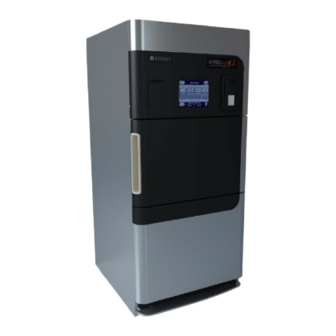
- Page 1 V-PRO maX 2 ® Low Temperature Sterilization System Operator Manual 10085896 Revision H...
- Page 2 Please refer to the Sterilant package insert for additional information. Any alteration of the Sterilization System not authorized or performed by STERIS which could affect its operation will void the warranty, could adversely affect operator safety, could adversely affect Sterilization efficacy and could violate national, state, or local regulations.
- Page 3 — A Word From STERIS • Entire Sterilizer (end-of-life) – Contact STERIS Corporation for disposal or recycling recommendations. • Oil from vacuum pump – Recyclable. Intended Use (North America) This Low Temperature Sterilization System using proprietary Sterilant is intended for use in the terminal Sterilization of properly prepared (cleaned, rinsed and dried, refer to Cleaning, Rinsing, and Drying) medical devices in Healthcare Facilities.
- Page 4 Sterilization process. A STERIS representative will gladly review these with you. Clinical Benefit The V-PRO maX 2 Low Temperature Sterilization System using VAPROX HC Sterilant is not directly used on patients. This Low Temperature Sterilization System using proprietary Sterilant is used to Sterilize critical and semi-critical medical devices in Healthcare Facilities.
- Page 5 — A Word From STERIS devices in Healthcare Facilities. The Sterilization Cycles operate at low pressure and temperature, suitable for processing medical devices sensitive to heat and moisture. NOTE: Refer to Component Identification of this manual for descriptions of the Sterilization System controls.
- Page 6 The system utilizes specially designed disposable Cartridges (Cups), available separately, containing proprietary Sterilant. STERIS maintains a complete line of accessories for this Sterilization system to simplify, organize and assure sterility of the Sterilization process. A STERIS representative will gladly review these with you.
- Page 7 — A Word From STERIS Clinical Benefit The V-PRO maX 2 Low Temperature Sterilization System using VAPROX HC Sterilant is not directly used on patients. This Low Temperature Sterilization System using proprietary Sterilant is used to Sterilize critical and semi-critical medical devices in Healthcare Facilities.
- Page 8 — A Word From STERIS Addresses 2797 EC Authorized Representative STERIS Ltd. STERIS House STERIS Ireland Limited IDA Business and Technology Park Jays Close Tullamore Viables County Offaly Basingstoke Hampshire R35 X865 Ireland RG22 4AX UNITED KINGDOM Manufactured by: STERIS Corporation 5960 Heisley Road Mentor, OH 44060–1834 USA...
-
Page 9: Table Of Contents
TABLE OF CONTENTS Section Number Description Page Safety Precautions ............................1 Introduction..........................1 DANGER — Slipping Hazard...................... 2 DANGER — Fire And Explosion Hazard..................2 DANGER — Personal Injury, Contaminated Load and/or Equipment Damage ..... 3 DANGER — Chemical Injury Hazard ..................3 WARNING —... - Page 10 Chamber Overtemp — ALM ....................54 Chamber Pressure Deviation — ALM ..................54 Chamber Temp Deviation — ALM ..................54 7.10 Chamber Undertemp — ALM....................55 7.11 Chemical Indicator Issue — NonALM ..................55 7.12 Control Data CRC Error — ALM....................56 7.13 Cup Empty —...
- Page 11 7.56 Too Long to Charge (Air Compressor) — ALM ............... 71 7.57 Too Long to Evacuate — ALM....................72 7.58 Too Long to Extend Tube — ALM ................... 73 7.59 Too Long To Fill (Reservoir) — ALM ..................73 7.60 Too Long to Heat Chamber —...
-
Page 12: Safety Precautions
Sheet (SDS). If misplaced, please contact STERIS for replacement. STERIS recommends that all operators should be regularly trained in the operation and safe usage of the equipment, including emergency procedures for any harmful material released into the environment. Records of attendance at training shall be maintained and evidence of understanding shall be demonstrated. -
Page 13: Danger - Slipping Hazard
A LATER TIME. Verify all materials coming in contact with hydrogen peroxide are compatible with oxidizers. Contact STERIS or the material manufacturer for information on material compatibility. This Sterilization Unit is not designed to process flammable liquids. Do not process liquids, linens, powders or any cellulose materials. -
Page 14: Danger - Personal Injury, Contaminated Load And/Or Equipment Damage
1 — Safety Precautions 1.4 DANGER — Personal Injury, Contaminated Load and/or Equipment Damage DANGER PERSONAL INJURY, CONTAMINATED LOAD AND / OR EQUIPMENT DAMAGE HAZARD Use only Sterilant Cups which have been specially formulated, tested and approved for use in this Sterilization System. Use of other sterilants could impair equipment operation, result in costly repairs, result in an ineffective Sterilization Cycle and void the equipment warranty. -
Page 15: Warning - Personal Injury And/Or Equipment Damage Hazard
WARNING PERSONAL INJURY AND/OR EQUIPMENT DAMAGE HAZARD Repairs and adjustments to this equipment must be made only by STERIS or STERIS- trained service personnel. Maintenance performed by unqualified personnel or installation of unauthorized parts could cause personal injury, result in improper equipment performance, invalidate the warranty or result in costly damage. -
Page 16: Warning Biohazard Control
Unit or ineffective Sterilization Cycle may not be detected. Use only BIs, CIs, BI Challenge Packs and other system accessories recommended by STERIS as these items have been validated to assure proper functioning with the Low Temperature Sterilization System. Ineffective Sterilization Cycle may not be detected using other system accessories. -
Page 17: Warning - Slipping Hazard
1 — Safety Precautions 1.10 WARNING — Slipping Hazard WARNING PERSONAL INJURY AND/OR EQUIPMENT DAMAGE HAZARD Changing vacuum pump oil could present a slipping hazard – promptly clean floor around unit. Wear Personal Protective Equipment (PPE; refer to Glossary) when cleaning floor of any vacuum pump oil. - Page 18 1 — Safety Precautions This Low Temperature Sterilization System should NOT be used to Sterilize liquids, linens, powders, or cellulose materials (refer to Material Compatibility). The Non Lumen and Fast Non Lumen (if equipped) Cycles should NOT be used to Sterilize non-stainless steel or non-titanium mated surfaces (refer to Material Compatibility).
-
Page 19: Glossary And Symbols
Cup or unloading Sterilization Unit. SDS – Safety Data Sheet. Sterilant –(VAPROX HC) – Proprietary STERIS 59% Hydrogen Peroxide Sterilant supplied in Cartridges. VAPROX HC Sterilant also contains stabilizers making it suitable for STERIS Sterilization Units. Sterilize – Either the second phase of the Sterilization Cycles or Sterilization of the load. Sterilization of a load occurs through use of an antimicrobial product to destroy microbes. -
Page 20: Hydrogen Peroxide Sterilization
2 — Glossary and Symbols Vac – Volts Alternating Current. Vdc – Volts Direct Current. VHP – STERIS proprietary technology utilizing Vaporized Hydrogen Peroxide. 2.2 Hydrogen Peroxide Sterilization Introduction This Low Temperature Sterilization System utilizes STERIS VHP Technology to provide a rapid, low-temperature, ®... - Page 21 2 — Glossary and Symbols The Sterilization Cycles DANGER PERSONAL INJURY, CONTAMINATED LOAD AND/OR EQUIPMENT DAMAGE HAZARD Processing a load containing a stainless-steel lumened instrument through the Non Lumen or Fast Non Lumen (if equipped) Cycle results in an ineffective Sterilization Cycle. Do not process stainless-steel lumened devices in a Non Lumen or Fast Non Lumen Cycle.
- Page 22 2 — Glossary and Symbols and load is tested for acceptable moisture content (up to three moisture evacuations). LOAD TEST REPEAT prints on cycle tape. NOTE: If Condition phase fails the third moisture check, the cycle aborts. • STERILIZE — This cycle phase consists of a series of either four pulses (Lumen, Flexible, Non Lumen) or two pulses (Fast Non Lumen).
-
Page 23: Symbols
2 — Glossary and Symbols • Four bars: 13 - 16 cycles remaining The chart below contains symbols which may be on your Sterilization System: inition of • Three bars: 9 - 12 cycles remaining Symbol Definition Symbols • Two bars: 5 - 8 cycles remaining •... - Page 24 Serial Number of the Unit 2 — Glossary and Symbols Table 2-2. Definition of Symbols on Sterilization System (continued) Symbol Definition Oxidizing Hazard Oxidizer Serial Number of Unit Corrosive Voltage Rating of Unit, Alternating Current Amperage Rating of Unit Three Phase Alternating Current Frequency Rating of Unit Phase of Unit ф...
- Page 25 2 — Glossary and Symbols Table 2-3. Definition of Symbols on Control Screens (continued) Symbol Definition Vacuum Pump and Filter Preventive Maintenance Required – Maintenance Required Shortly (Yellow) Yes Touch Pad No Touch Pad 10085896_H Operator Manual V-PRO maX 2 ®...
-
Page 26: Installation Verification
Only STERIS or STERIS-trained personnel should install this Low Temperature Sterilization System. After the Sterilization System is installed according to the provided instructions, complete the following checklist to ensure the installation is complete and correct. Or, if so desired, contact STERIS to schedule an installation verification and/or a demonstration of proper equipment operation. - Page 27 ◻ Load has been thoroughly cleaned, rinsed and dried (refer to Cleaning, Rinsing, and Drying). ◻ Only use a STERIS approved BI and Challenge Pack for use in this Sterilization Unit (refer to Biological Indicator Challenge Pack). In the U.S., use only a FDA-cleared BI and Challenge Pack for use with this Low Temperature Sterilization System.
-
Page 28: Technical Specifications
3 — Installation Verification 3.3 Technical Specifications This section includes the following topics: Overall Size (W x L x H) Operating Weight Electric Requirements Environmental Conditions Sterilant Equipment Drawings Cycle Limits Overall Size (W x L x H) • 33 x 37-7/8 x 75-1/8” (838 x 962 x 1908 mm) Recessed •... - Page 29 3 — Installation Verification Sterilant • VAPROX HC Sterilant: 59% H (wt/wt) concentration This device complies with: part 15 of the FCC Rules; EN 301 489–1 v2.1.0 (2016–09) and EN 301 489–3 v2.1.1:2017. Operation is subject to the following two conditions: (1) This device may not cause harmful interference, and (2) this device must accept any interference received, including interference that may cause undesired operation.
- Page 30 3 — Installation Verification Table 3-1. Cycle Limits (North America) (continued) Lumen ID Lumen Lumens Per Cycle Name Weight Limit Device Type lb (kg) Length mm Load ≥ 1.3 ≤ 73 Dead end lumens Table 3-2. Cycle Limits (Outside North America) Cycle Name Weight Limit Device Type...
-
Page 31: Hydrogen Peroxide Handling
Precautions Section of this manual before handling the Sterilant Cups. Also, read, comply with and save the Sterilant Safety Data Sheet (SDS). If misplaced, please contact STERIS for replacement. IMPORTANT: The Low Temperature Sterilization System is designed to minimize operator potential contact with H . -
Page 32: Sterilant Cup Installation And Removal
4 — Hydrogen Peroxide Handling DANGER FIRE AND EXPLOSION HAZARD Liquid hydrogen peroxide is a strong oxidant and poses a FIRE, EXPLOSION OR CONTAINER RUPTURE HAZARD. Avoid excessive heat, contamination or contact with combustible materials. Clothing, shoes or other combustible materials that have come in contact with hydrogen peroxide must be immediately and thoroughly washed with water. - Page 33 4 — Hydrogen Peroxide Handling The Low Temperature Sterilization Unit Control automatically tracks the amount of Sterilant used and sterilant expiration date and prompts the user on the control display when a new Cup is needed (see Figure 4-1). The proprietary Sterilant Cup (PB011 and PB012) is equipped with a RFID chip and a data matrix code to ensure the correct Cup is used and is not expired (see Figure 4-2).
- Page 34 4 — Hydrogen Peroxide Handling • To dispose an expired Cup, ensure chamber is empty and press Green Check (Yes) touch screen to initiate Cup Dispose Cycle (see Figure 4-3). Data Matrix Code, Lot Number, Expiration Date Figure 4-2. Sterilant Cup Label (Typical) 10085896_H V-PRO maX 2...
- Page 35 4 — Hydrogen Peroxide Handling Figure 4-3. Control Screens: Sterilant Cup 10085896_H Operator Manual V-PRO maX 2 ®...
- Page 36 4 — Hydrogen Peroxide Handling Figure 4-4. Install/Remove Sterilant Cup 10085896_H V-PRO maX 2 Operator Manual ®...
-
Page 37: Component Identification
Compatibility). Uses other than as specified and described in these instructions are not recommended, may not be effective in Sterilization and may not be safe. Consult STERIS for further information. The system utilizes specially designed disposable Cups (available separately) containing proprietary Sterilant. - Page 38 5 — Component Identification • Printer — Located on OE of single door Sterilization Unit (NOE of double door Unit) on right side of control panel. This alphanumeric thermal printer provides an easy-to-read permanent record of Sterilization Cycle. Printer provides 24-character wide cycle tape. NOTE: The thermal paper, under proper storage conditions, is able to achieve a 25-year shelf life.
-
Page 39: Control Displays (Touch Screens)
• Service Screens – Light Blue; require access code (e.g., INPUT/OUTPUT STATUS and CALIBRATION MENU). These screens are for qualified STERIS-trained service personnel and are not discussed in this manual. • Option Screens – Purple (e.g., PRINT OPTIONS and CHANGE DATE/TIME). -
Page 40: Alarm Screens
5 — Component Identification NOTE: Control Display alerts the user to replace an invalid, expired or spent Sterilant Cup prior to starting a cycle. • Generally, when the Sterilization Unit is in-cycle, displays appear automatically and, unless an abnormal condition occurs, require no special operator attention or instructions. - Page 41 5 — Component Identification NOTE: For Control Display touch panel screen touch pad definitions, refer to Symbols. When an alarm occurs during cycle operation, a red screen appears on the display, accompanied by an audible tone. This screen indicates the problem as determined by control sensors. The operator should follow the instructions on the screen, if possible.
-
Page 42: Thermal Printer
5 — Component Identification Abort Touch Pad Figure 5-6. Abort Touch Pad 5.5 Thermal Printer The Sterilization Unit is equipped with a thermal printer. NOTE: Front cover is magnetically held closed. Printer records all cycle data on 2-1/4" (57 mm), 24 character, wide single-ply paper. Refer to Change Printer Paper Roll for paper changing procedure. -
Page 43: Operation
Uses other than as specified and described in these instructions are not recommended, may not be effective in Sterilization and may not be safe. Consult STERIS for further information. The system utilizes specially designed disposable cartridges (available separately) containing proprietary Sterilant. -
Page 44: Before Operating Sterilization Unit
6 — Operation NOTE: Before operating this Sterilization System, all installation requirements must be met. Please refer to Installation Verification. 6.4 Before Operating Sterilization Unit The following steps must be performed daily prior to Low Temperature Sterilization System usage: 1. Ensure chamber interior is clean. Refer to General Section if cleaning is necessary. 2. - Page 45 6 — Operation TURN POWER ON (Power-Up Screen) Pop-Up Service Mode (Touch Screen Icon) Touch Pad NOTE: SELECT CYCLE screen differs when Specialty Cycles are enabled. Refer to Specialty Cycle Screens Illustration (Figure 7-9). Figure 6-1. Unit Start-Up 10085896_H Operator Manual V-PRO maX 2 ®...
-
Page 46: Load Sterilization Unit
Load the Sterilization Unit as follows: NOTE: STERIS recommends (in accordance with applicable ANSI/AAMI guidelines) wearing chemical-resistant gloves when using the Sterilization Unit. 1. Pull chamber door open or step on the foot pedal. - Page 47 Ensure loads placed into the Sterilizer do not exceed stated weight, packaging or lumens (number, size or type) depending on the Sterilization Cycle chosen. g. To reduce wear on sterile packaging, STERIS recommends that the shelf is slid out, load placed on shelf, then slide shelf and load back into chamber.
-
Page 48: Vhp Sterilization Cycle Operation
FIRE AND EXPLOSION HAZARD ● Verify all materials coming in contact with hydrogen peroxide are compatible with oxidizers. Contact STERIS or the material manufacturer for information on material compatibility. ● This Sterilization Unit is not designed to process flammable liquids. Do not process liquids, linens, powders or any cellulose materials. - Page 49 6 — Operation DANGER PERSONAL INJURY, CONTAMINATED LOAD AND/OR EQUIPMENT DAMAGE HAZARD ● Processing a load containing a stainless-steel lumened instrument through the Non Lumen or Fast Non Lumen (if equipped) Cycles results in an ineffective Sterilization Cycle. Do not process stainless-steel lumened devices in a Non Lumen or Fast Non Lumen Cycle.
- Page 50 6 — Operation NOTE: For Control Display touch panel screen touch (Power-Up Screen) pad definitions, refer to YMBOLS (Touch Screen) ONTROL PTIONS (Or) (Press Touch (Or) Pad) (Or) (Press Touch Pad) Status Screen Touch Pad (Double Door Screens Shown) NOTE: For OPERATING screen displayed times and pressures, note the following: 1) Projected cycle completion time shown on display is estimated.
- Page 51 6 — Operation • Non Lumen Cycle: Non-lumened instruments or instruments with mated surfaces (such as hinged portion of forceps and scissors) may be processed in this cycle. • Fast Non Lumen Cycle: If the load contains only pouched non-lumened instruments and weighs less than 11 lb (5 kg), it may be processed in the Fast Non Lumen Cycle.
- Page 52 6 — Operation Figure 6-5. OPTIONS Screen Figure 6-6. Out-Of-Cycle STATUS Screen 10085896_H V-PRO maX 2 Operator Manual ®...
- Page 53 6 — Operation Figure 6-7. Verify Load Screen Figure 6-8. OPERATING Screen Control Options Parameters of the Sterilization Unit Cycles are not adjustable; however, operator and supervisor (refer to Appendix B) have some options available. Pressing Options icon on SELECT CYCLE screen displays OPTIONS screen as shown below: 10085896_H Operator Manual V-PRO...
- Page 54 6 — Operation Refer to PPENDIX (Refer to ECTION (Return to SELECT CYCLE Screen) Status Screen Touch Pad Aborting Cycles Toggles Between LOW, MEDIUM, HIGH (Save Values and Return to OPTIONS Screen) (Save Values and Return to OPTIONS Screen) (Save Value and Return to SET TIME Screen)
- Page 55 6 — Operation NOTE: For Control Display touch panel screen touch pad definitions, refer to Table 2-3. 1. Leak Test – Pressing this touch pad displays OPERATING screen. Leak Test time counts down on screen. Abort touch pad is located in lower right corner. Leak Test passes through three phases: Cycle Preparation, Leak Test and Aerate.
- Page 56 6 — Operation Sterilization Cycle can be aborted any time during normal unit operation. If a cycle is aborted, the load must be repackaged and reprocessed. NOTE: For Control Display touch panel screen touch pad definitions, refer to Symbols. To abort the VHP Sterilization Cycle in progress, see below. NOTE: For Control Display touch panel screen touch pad definitions, refer to Symbols...
- Page 57 Pressing Back Arrow touch pad (lower left) returns CYCLE (or Ready) screen to control display. 3. When Abort phase is complete, ABORT Complete screen is displayed. NOTE: STERIS recommends (in accordance with ANSI/AAMI ST58, 2013) wearing chemical-resistant gloves when removing items from the Sterilization Unit after a cycle has been aborted.
- Page 58 6 — Operation (Refer to (Refer to ACUUM AINTENANCE NDICATOR (Refer to TERILANT NSTALLATION ND REMOVAL 10085896_H V-PRO maX 2 Operator Manual ®...
- Page 59 ANSI/AAMI ST58, 2013, recommends using chemical-resistant gloves when using the Sterilization Unit. NOTE: STERIS recommends leaving Sterilization Unit powered ON and door closed when not in use. Unit needs approximately 45 minutes once SELECT CYCLE screen displays to reach operating temperature if turned OFF.
-
Page 60: Troubleshooting
NOTE: When an alarm occurs the printer automatically generates a printout. Refer to Typical Alarm Printouts Section. If a problem occurs that cannot be corrected using this section or is not described in this section, please call STERIS. A trained service technician will promptly place your Sterilization Unit in proper working condition. -
Page 61: Typical Alarm Screen
If alarm is reset or cleared, CYCLE screen appears on display. If alarm is not reset or cleared, ALARM screen reappears and STERIS must be called to correct the situation. • Alarm Silence — Pressing this touch pad orders control to silence audible alarm. -
Page 62: Typical Alarm Printout
7 — Troubleshooting Figure 7-2. Alarm Status Screen 7.3 Typical Alarm Printout When an alarm occurs the printer automatically generates a printout (see Figure 7-3). This printout typically lists alarm name, time alarm occurred, current chamber status and any associated sensor temperatures. 10085896_H V-PRO maX 2... -
Page 63: Alarm Types
7 — Troubleshooting Figure 7-3. Typical Alarm Printout 7.4 Alarm Types The Sterilization Unit control is equipped with four alarm types as follows: NOTE: The operator may abort any cycle before scheduled completion by simply pressing the Abort Touch Pad (Inverted Red Triangle). -
Page 64: Air Utility Failure - Alm
BI not used properly; ampule not crushed. 1. Refer to BI IFU for proper use. Incubator failure. 1. Try different Incubator. Chamber leak. 1. Run Leak Test cycle. Initiate cycle from Options screen. 2. If test fails, contact STERIS. 10085896_H V-PRO maX 2 Operator Manual ®... -
Page 65: Chamber Overtemp - Alm
Acknowledge alarm. 1. Load must be repackaged and reprocessed after Abort Phase is completed. Run empty Non Lumen cycle. 1. If it passes, place back into Service. 2. If it fails, contact STERIS. 10085896_H Operator Manual V-PRO maX 2 ®... -
Page 66: Chamber Undertemp - Alm
(59 F). Check chamber temperature on status screen. 1. If at least 49.5 C, reprocess load and rerun cycle. 2. If temperature is below 49.5 C, contact STERIS. 7.11 Chemical Indicator Issue — NonALM Condition Chemical Indictor did not change color or change enough to show good sterilization (Non-Alarm). -
Page 67: Control Data Crc Error - Alm
If CRC value for cycle data changes during cycle, cycle aborts. NOTE: Monitored every second whenever machine is in any cycle. General Troubleshooting Additional Information Acknowledge alarm. 1. Contact STERIS. 2. Load must be repackaged and reprocessed after Abort Phase is completed. 7.13 Cup Empty — ALM Condition Occurs if cartridge empty sensor (LS12) does not sense H2O2 in line after 10 seconds from start of phase. -
Page 68: Cup Invalid
Condition Cup Receiver Door Does Not Open when Cup is Empty. Cup Receiver Door Does Not Stay Locked (Closed) with Sterilant remaining in Cup. General Troubleshooting Additional Information Contact STERIS. 1. Contact STERIS. 10085896_H V-PRO maX 2 Operator Manual ®... -
Page 69: Cup Receiver Open - Alm
Cup when the cycle is started. (Cup is not punctured until a cycle is started). If cycle passes, place Unit back into service. 3. If cycle does not pass, contact STERIS. Cartridge Interface receiver door is closed. 1. Contact STERIS. -
Page 70: Door Issue - Nonalm
Additional Information Vacuum holding door closed. 1. Wait 15 minutes and try to open door again. 2. If door does not open, call STERIS. 7.22 Door Open — ALM Condition Occurs if door A or B closed switch (LS1/LS2) opens during a cycle. Sterilizer automatically aborts cycle. -
Page 71: Door Unlocked - Alm
Acknowledge alarm. 1. If alarm clears, run empty cycle. 2. If it passes, place Unit back into service. 3. If alarm does not clear, contact STERIS. 7.26 Failure Reading PT1 — ALM Condition Occurs if PT1 is reading outside of normal range. -
Page 72: Failure Reading Pt2 - Alm
Occurs if PT2 is reading outside of normal range. General Troubleshooting Additional Information Acknowledge alarm. 1. Load must be repackaged and reprocessed after Abort Phase is completed. Call STERIS. 7.28 Failure Reading RTD1 — ALM Condition Occurs if RTD1 (Vaporizer) is reading outside of normal range. General Troubleshooting Additional Information Acknowledge alarm. -
Page 73: Failure Reading Rtd4 - Alm
General Troubleshooting Additional Information Acknowledge alarm. 1. Cycle power on Unit. 2. Contact STERIS if alarm does not clear. 3. Cycle only aborts if printer is disabled. Load must be repackaged and reprocessed after Abort Phase is completed. 7.33 Injection Limit Reached... -
Page 74: Inject Switch Failure - Alm
Communication with IO board has been lost. Monitored whenever system has power following boot process. General Troubleshooting Additional Information Acknowledge alarm. 1. Cycle power on Unit. 2. Contact STERIS if alarm does not clear. 3. Load must be repackaged and reprocessed after Abort Phase is completed. 7.36 Leak Test Failure — ALM Condition Occurs if the measured leak rate in the chamber is above 0.30 mmHg/min (torr), chamber door remains locked. -
Page 75: Load Too Wet - Alm
Chamber leak. 1. Run leak test. 2. If leak test fails, contact STERIS. 7.38 LS10 Switch Failure — ALM Condition LS10 is in cylinder retracted position at cycle start or is disconnected from Unit. Monitored only at start of a cycle. -
Page 76: Ls11 Switch Failure - Alm
Occurs if there is an error reading data from non-volatile memory. General Troubleshooting Additional Information Acknowledge alarm. 1. Cycle power on Unit. 2. Contact STERIS if alarm does not clear. 3. Load must be repackaged and reprocessed after Abort Phase is completed. 10085896_H V-PRO... -
Page 77: Memory Write Error - Alm
Unit power off. 1. Verify facility power. 2. Turn Unit power ON. 3. If Unit still has no power, contact STERIS. 7.44 Odor or Oil Misting from Unit — NonALM Condition Odor caused by oil mist coming from vacuum pump oil exhaust filter (Non-Alarm). -
Page 78: Power Failure - Alm
Cycle Pass, there is no need to reprocess load. Power outage at Facility. 1. Verify power loss on Unit not Facility. 2. Contact STERIS. Facility 3–phase voltage issue. 1. Ask Maintenance to verify 208 V on all legs of 3– phase voltage. -
Page 79: Pressure Rise Low - Alm
Printer is unresponsive or does not print properly (Non-Alarm). General Troubleshooting Additional Information No paper on roll or incorrect thermal paper installed. 1. Verify correct paper and correct loading on thermal printer. 2. If issue not corrected, contact STERIS. 10085896_H Operator Manual V-PRO maX 2 ®... -
Page 80: Printer Failure - Alm
3. Cycle power to Unit after loading paper if printer is buzzing. 4. Contact STERIS if alarm does not clear. 5. Unit can still be used as cycles are stored in log and can be printed later or saved to USB. -
Page 81: Reservoir Overfill - Alm
Prints Task xx Error ##. General Troubleshooting Additional Information Acknowledge alarm. 1. Contact STERIS; Unit may continue to be used. 2. If alarm occurs during cycle, load must be repackaged and reprocessed after Abort Phase is completed. Reboot issue. -
Page 82: Too Long To Air Break - Alm
NOTE: PS1 is a normally open switch that closes when air pressure is above 60 psig. General Troubleshooting Additional Information Acknowledge alarm. 1. If alarm clears, run cycle. 2. If alarm won't clear, contact STERIS. 10085896_H V-PRO maX 2 Operator Manual... -
Page 83: Too Long To Evacuate - Alm
7 — Troubleshooting 7.57 Too Long to Evacuate — ALM Condition Occurs if target vacuum level is not reached after 15 minutes of phase start. Sterilizer automatically aborts cycle. General Troubleshooting Additional Information Acknowledge alarm. 1. Load must be repackaged and reprocessed after Abort Phase is completed. -
Page 84: Too Long To Extend Tube - Alm
1. If alarm clears, run empty chamber Non Lumen Cycle. 2. If it passes, place unit back into service. 3. If alarm does not clear, contact STERIS. 7.59 Too Long To Fill (Reservoir) — ALM Condition Occurs if reservoir fill sensor (LLS1) does not sense H2O2 within 100 seconds from start of phase. Sterilizer automatically aborts cycle. -
Page 85: Too Long To Heat Chamber - Alm
2. Wait for chamber temperature to reach 49.5 C (121 F), select cycle. 3. Check Status screen to ensure temperature is increasing. 4. If chamber does not heat, contact STERIS. Facility 3–phase voltage issue. 1. Ask Maintenance to verify 208 V on all legs of 3– phase voltage. -
Page 86: Too Long To Inject - Alm
Abort Phase is completed. Run empty Non Lumen cycle. 1. If it passes cycle, place back into service. 2. If it alarms again, contact STERIS. 7.63 Too Long to Inject Fill — ALM Condition Occurs if time between start of injection fill (SV8 energizes) and fill complete (LS11 closes) exceeds eight seconds. -
Page 87: Too Long To Lock Door - Alm
Acknowledge alarm. 1. If door opens, run empty chamber Non Lumen test cycle. If cycle passes put Unit back into service. 2. If cycle does not pass, contact STERIS. 7.65 Too Long to Retract Tube — ALM Condition Occurs if LS9 does not sense draw tube retracted within three seconds of SV14 activation. -
Page 88: Unit Does Not Alarm When Cup Is Empty - Nonalm
General Troubleshooting Additional Information Verify Cup is empty. 1. Select cycle. If Unit starts cycle, Cup is not empty. 2. If cycle does not start, contact STERIS. 7.68 Unit Not Calibrated — ALM Condition Unit displays UNIT NOT CALIBRATED. General Troubleshooting Additional Information Control issue. -
Page 89: Vaporizer Temp Deviation - Alm
1. If temperature is at least 59.5 C (139 F), reprocess load and rerun cycle. 2. If temperature is below 59.5 C (139 F), contact STERIS. Room too cold. 1. Verify room temperature near unit is above 15 C or 59 F. -
Page 90: Routine Maintenance
Unit configuration that is inconsistent with the validated, FDA cleared product. The STERIS warranty is void if components are used that are not approved. DO NOT USE components that are not validated as part of this Low Temperature Sterilization System. -
Page 91: Routine Operator Maintenance
8 — Routine Maintenance NOTE: Never permit unqualified persons to service this Sterilization Unit. 8.3 Routine Operator Maintenance This section includes the following: Introduction Daily Weekly Monthly Introduction Perform the following routine maintenance procedures as indicated in Daily, Weekly, and Monthly. Daily Check printer paper supply. - Page 92 Sterilization Cycle and void the equipment warranty. NOTE: Use only Sterilant provided in STERIS designed Cups (Cartridges) in this Low Temperature Sterilization System. STERIS Sterilant Cartridges contain high purity hydrogen peroxide and are produced under controlled conditions to assure effectiveness through the expiration date stamped on the label.
- Page 93 8 — Routine Maintenance Cleaning Chamber DANGER SLIPPING HAZARD Water or hydrogen peroxide spilled on the floor presents a slipping hazard – promptly clean up the spill. If in doubt whether the liquid is water or hydrogen peroxide, assume spill is hydrogen peroxide. Put on appropriate Personal Protective Equipment (PPE;...
-
Page 94: Leak Test
8 — Routine Maintenance 8.5 Leak Test WARNING ABORTED CYCLE HAZARD A leak test is recommended to be performed monthly on the Sterilization Unit to ensure chamber leak rate is within specification. The leak rate must be less than 0.3 Torr/minute (0.4 mbar/minute or 0.04 kPa/minute). If not, an abort results, door remains locked and Sterilization Unit service is required. - Page 95 8 — Routine Maintenance 4. CHAMBER EMPTY screen appears. 5. Press Green Check (Yes) touch pad. 6. OPERATING screen displays. 7. Leak Test time counts down on screen. Abort touch pad is located in lower right corner. Leak Test passes through three phases: Cycle Preparation, Leak Test and Aerate as follows: •...
-
Page 96: Change Printer Paper Roll
Printouts). Leak rate must be less than 0.3 Torr/minute (0.04 kPa/minute; 0.4 mBar/minute) to pass test. If not, Sterilization Unit alarms and door remains locked. Contact STERIS. 8.6 Change Printer Paper Roll This Low temperature Sterilization System includes a thermal printer. Load or replace printer paper roll (10092606, pack of 3 rolls) as follows: NOTE: If the paper runs out during a cycle, the last 300 cycles can be reprinted. - Page 97 8 — Routine Maintenance Use Blue Tab to Lift Inside Cover 3. Remove old paper spool. Remove Old Printer Paper Spool 4. Add new paper roll as follows : a. Position paper roll in bottom of printer compartment, paper coming from bottom of roll. b.
-
Page 98: Preventive Maintenance Schedule
WARNING PERSONAL INJURY AND/OR EQUIPMENT DAMAGE HAZARD ● Repairs and adjustments to this equipment must be made only by STERIS or STERIS- trained service personnel. Maintenance performed by unqualified personnel or installation of unauthorized parts could cause personal injury, result in improper equipment performance, invalidate the warranty or result in costly damage. -
Page 99: Vacuum Pump Maintenance Indicator
For Preventive Maintenance, note the following: 1. Regular service and maintenance MUST be performed only by STERIS or STERIS-trained technician. Any work performed by inexperienced or unqualified persons or installation of unauthorized parts could cause personal injury, invalidate warranty or result in costly damage. -
Page 100: Replacement Parts
Ordering Information Recommended Spare Parts Introduction Use only STERIS-authorized parts on this equipment. Use of unauthorized parts voids the warranty. Ordering Information To order replacement parts and/or supply products, proceed as follows: 1. Include part number and description as listed in Supply Products and Recommended Spare Parts. - Page 101 P093940310 FILTER, Carbon FILTER, Noise P129385406 NUT, Flangeless P387349030 P764334644 OIL, Vacuum Pump, V-PRO maX 2 Units (3 Liters) P764335529 OIL, Vacuum Pump, V-PRO s2 Units (1 Liters) 10092606 PAPER, Thermal Printer (Box of 3) P093922107 PROBE, RTD (Dual Element)
-
Page 102: Printouts
On power up the following printout is generated that includes the software information and the serial number. ********* POWER UP ********* DATE: 08/02/21 TIME: 11:16:18A STERILIZER NO: MACHINE TYPE: V-PRO MAX 2 SERIAL # SOFTWARE 10288251 V 1.83.2 r1250 AUG10 2020 12:30:47 Firmware, IO Board #1 10079098v01.00.09 **************************** Service Mode Upon successfully entering Service Mode, SERVICE Menu screen and the following typical printout occurs. - Page 103 9 — Printouts ======================== 07-05-21 11:16:18 Service Mode Enter ======================== ======================== 07-05-21 11:23:32 Service Mode Exit ======================== Calibration From. PRINT CAL REPORTS screen, press appropriate touch pad and Control orders printer to complete CALIBRATION DATA printout (typical) as follows: 10085896_H Operator Manual V-PRO maX 2...
- Page 104 9 — Printouts ****CALIBRATION DATA**** 3/18/19 13:54:30 SERIAL # 030021901 **CURRENT CALIBRATION** Chamber Pressure Low PT1 Sensor: 10V 3/12/19 14:45:38 Cal. Name: Cal type: Edit LOW RAW = 8390937 HIGH RAW = 12790467 LOW VALUE = 0.10 Torr HIGH VALUE = 23.000 Torr **CURRENT CALIBRATION** Chamber Pressure High PT2 Sensor: 4 to 20...
- Page 105 9 — Printouts Cycle and Leak Test NOTE: Control of printouts is accessed through SUPERVISOR screen. The printout reports useful information about each cycle the Sterilization Unit processes. NOTE: The displayed cycle times in the included cycle tapes are typical only. Cycle time is dependent on multiple factors (load size, configuration, etc.) which may impact overall cycle time.
- Page 106 9 — Printouts Sterilize Cycle Name Sterilant Expiration Date Temperature Pressure Start Pulse 1 Pressure Rise Pulse 1 Pressure Transition Pulse 2 Pulse 2 Pulse 3 Pulse 3 Pulse 4 Pulse 4 Sterilize Time Sterilization Cycle Complete Figure 9-1. Labelled Extended Lumen/Flexible Cycle Printout (Typical) 10085896_H V-PRO maX 2...
- Page 107 9 — Printouts Sterilize Cycle Name Sterilant Expiration Date Temperature Pressure Start Pulse 1 Pressure Rise Pulse 1 Pressure Transition Pulse 2 Pulse 2 Pulse 3 Pulse 4 Sterilize Time Sterilization Cycle Complete Figure 9-2. Labelled Extended Non Lumen/Fast Non Lumen Cycle Printout (Typical) 10085896_H Operator Manual V-PRO...
- Page 108 9 — Printouts Figure 9-3. Leak Test Printout (Typical) Printer Self Test The self-test printout (Figure 9-4) consists of the printer's current Model, H/W Revision, F/W Revision, Memory, RS232 Setting, the Print Mode, the Option Register, and two sample font print outs. 10085896_H V-PRO maX 2...
- Page 109 9 — Printouts Figure 9-4. Printer Self Test (Typical) Typical Alarm Printout When an alarm occurs the printer automatically generates a printout (see Figure 9-5). This printout typically lists alarm name, time alarm occurred, current chamber status and any associated sensor temperatures. 10085896_H Operator Manual V-PRO...
- Page 110 9 — Printouts Figure 9-5. Typical Alarm Printout 10085896_H V-PRO maX 2 Operator Manual ®...
-
Page 111: Cleaning, Rinsing And Drying
Sterilization inactivates any remaining spores and living microorganisms. STERIS recommends the following general cleaning process: NOTE: This is a general process and is not intended to replace facility procedures and current protocols. -
Page 112: Packaging And Loading
10 — Appendix A 3. Drying: a. Dry all items thoroughly. b. Ensure ALL moisture is removed from all internal parts (including lumens). If not, residual H2O2 may remain at cycle completion and/or a cycle Abort occurs. c. Only dry items are to be placed in Sterilization Unit. NOTE: One acceptable lumen drying method is to blow compressed air through the lumen until no moisture exits at the lumen distal end. - Page 113 PERSONAL INJURY, CONTAMINATED LOAD AND/OR EQUIPMENT DAMAGE HAZARD Failure to follow the V-PRO Sterilization Tray or the V-PRO Instrument Organizers operating instructions could result in an ineffective Sterilization Cycle. STERIS recommends use of the V-PRO or PRO-LITE Sterilization Trays and accessories for use in this Low ™...
- Page 114 10 — Appendix A NOTE: If using a non-STERIS tray or container that has been FDA cleared for use in this Low Temperature Sterilization System, follow manufacturer’s instructions for preparation and loading. Device Wraps Select the proper size wrap for the items to be Sterilized. Use only Low Temperature Sterilization System compatible polypropylene sterilization wrap (contact STERIS or your local distributor to identify compatible wraps in your market).
- Page 115 • Maximum allowable load per shelf is 42 lb (19 kg). Ensure loads placed into Sterilizer do not exceed stated weight, packaging or lumens (number, size or type) depending on Sterilization Cycle chosen. • To reduce wear on sterile packaging, STERIS recommends to slide shelf out, place load on shelf, then slide shelf and load back into chamber.
- Page 116 10 — Appendix A Steris Lore Sent to you by Hello, This is the lores we images, there is no which ones were n Let me know if you Figure 10-1. Correctly Loaded Low Temperature Sterilizer Chamber Material Compatibility Table 10-1. Materials Compatible With Sterilant...
- Page 117 10 — Appendix A Table 10-1. Materials Compatible With Sterilant (continued) Plastics Metals Silicone Teflon (polytetrafluoroethylene, PTFE) ® 1 Ultem Polymers (polyetherimide, PEI) ® 3 Coatings Ceramics and Others Alumina (Al Aluminum Titanium Nitride (AlTiN) Diamond, Ruby, Sapphire Aluminum Titanium Nitride Chromium Nitride (AlTiN CrN) Glass Diamond Like Carbon (DLC) Silicone Nitride (Si...
- Page 118 10 — Appendix A Table 10-2. Materials NOT Compatible With Sterilant (continued) Materials NOT Compatible With Hydrogen Peroxide Items with mated Nylon surfaces ® 1 Single use items (manufacturer does not recommend re-sterilization) Implants where manufacturer has not specifically recommended sterilization in this Low Temperature Sterilization System Instruments and devices that cannot withstand a vacuum and are labeled for gravity steam sterilization methods only...
-
Page 119: Appendix B (Supervisor Screens)
11 — Appendix B (Supervisor Screens) Appendix B (Supervisor Screens) This section includes the following topics: Supervisor Screen Machine Setup Screen Date/Time Screens Delayed Start Screens Cycle Print Log Screens Supervisor Screen This Appendix is to be used as a supplement to Operating Instructions. The supplied information enables the Supervisor to setup or adjust certain control functions of this Low Temperature Sterilization System. - Page 120 11 — Appendix B (Supervisor Screens) Return to OPTIONS Screen Section Section Return to OPTIONS Screen Section Section Return to SUPERVISOR Screen Toggles Between Return to SUPERVISOR Screen Machine Setup Screen The MACHINE SETUP screen enables the Supervisor to setup the printer, give Sterilizer an ID, setup how the units are displayed and determine language screens and printout display.
- Page 121 11 — Appendix B (Supervisor Screens) Return to SUPERVISOR Screen Save Data and Return to MACHINE SETUP Screen Return to MACHINE SETUP Screen Toggles Between Toggles Between EXPANDED Toggles Between CONDENSED ENABLED DISABLED Toggles Between ENABLED DISABLED Toggles Between Save Data and Return to SUPERVISOR Screen Save Data and Pressing this touch pad displays STERILIZER Return to...
- Page 122 11 — Appendix B (Supervisor Screens) Date/Time Screens The CHANGE DATE/TIME screen enables the Supervisor to set the time and date on the Sterilizer. Save Values and Return to SUPERVISOR Screen Return to CHANGE DATE/TIME Screen Return to CHANGE DATE/TIME Screen Pressing this touch pad displays Set Time Pressing this touch pad displays Set Month Number on a key pad screen.
- Page 123 11 — Appendix B (Supervisor Screens) Delayed Start Screens The DELAYED START screen enables the Supervisor to setup the Sterilizer to complete a Lumen, Non Lumen, Fast Non Lumen, or Flexible Cycle at a later time. * * * Return to SUPERVISOR Screen Return to DELAYED START Screen Return to SET TIME Screen Return to SET TIME Screen...
- Page 124 11 — Appendix B (Supervisor Screens) Cycle Print Log Screens The CYCLE LOG screen enables the Supervisor to print the Sterilizer Cycle and data or store this information on a USB device. Return to SUPERVISOR Screen Scroll Up and Down Return to CYCLE LOG Screen Return to CYCLE LOG Screen Upon Completion of Copy Function or if CANCEL Button is...
- Page 125 However, due to the complexity of certain flexible endoscopes, this testing cannot confirm compatibility of all devices that meet the claims for each sterilization cycle. Please contact the device manufacturer or STERIS to ensure compatibility of specific devices with this Low Temperature Sterilization System with the intended device.
- Page 126 12 — Appendix C 10085896_H V-PRO maX 2 Operator Manual ®...
Need help?
Do you have a question about the V-PRO maX 2 and is the answer not in the manual?
Questions and answers
how can I retrieve a past print out from the vrpo max unit