
Related Manuals for LINET Multicare X


Summary of Contents for LINET Multicare X
- Page 1 Instructions for Use and Technical Description Multicare X Positionable Bed for Intensive Care version with scales D9U001MCX-0101 Version: 03 Publication Date: 2021-12...
- Page 2 274 01 Slaný Tel.: +420 312 576 111 Fax: +420 312 522 668 E-mail: info@LINET.cz http://www.LINET.com Service department: service@linetgroup.com Multicare X Positionable bed for intensive care version with scales Author: L I N E T, s.r.o. Related links: www.linet.com D9U001MCX-0101...
-
Page 3: Table Of Contents
1.5 Symbols and Labels on the Bed .........7 12.6 Lateral Tilt Foot Control (standard) ......76 1.6 Serial Label with UDI ..........13 13 Bed Positioning ............77 1.6.1 Serial Label for Multicare X with scales ....13 13.1 Backrest ..............77 1.7 Acoustic signalisation ..........14 13.2 Thighrest ..............78 1.8 Visual signalisation............14... - Page 4 19.20 Advanced Stabilising ALT Pads ....... 159 19.21 Foldable IV & Drive (Infusion Stands/Pushing Handles) ..................160 20 Cleaning/Disinfection ..........163 20.1 Cleaning (Multicare X) ..........164 20.1.1 Daily Cleaning ............164 20.1.2 Cleaning before Changing Patients ....... 164 20.1.3 Complete Cleaning and Disinfection ...... 165 21 Troubleshooting ............166...
-
Page 5: Symbols And Definitions
1 Symbols and Definitions 1.1 Warning Notices 1.1.1 Types of Warning Notices Warning notices are differentiated by the type of danger using the following signal words: ► CAUTION warns about the risk of material damage. ► WARNING warns about the risk of physical injury. ► DANGER warns about the risk of fatal injury. 1.1.2 Structure of Warning Notices SIGNAL WORDS! Type and source of danger! ►... -
Page 6: Symbols On The Package
1.4 Symbols on the Package FRAGILE, HANDLE WITH CARE THIS WAY UP KEEP DRY (PROTECT FROM HUMIDITY) PAPER RECYCLING SYMBOL DO NOT STACK DURING STORAGE DO NOT USE HAND TRUCK HERE OVERSEAS PACKAGE: STACKING LIMIT BY NUMBER (3 PACKAGES FOR TRANS- PORT) OVERSEAS PACKAGE: STACKING LIMIT BY NUMBER (5 PACKAGES FOR STORAGE) D9U001MCX-0101_03... -
Page 7: Symbols And Labels On The Bed
1.5 Symbols and Labels on the Bed READ INSTRUCTIONS FOR USE GO BUTTON (PRESS TO ACTIVATE CONTROL ELEMENT) STOP BUTTON (PRESS TO INTERRUPT BED POSITIONING) MANUFACTURER MANUFACTURING DATE REFERENCE NUMBER (PRODUCT TYPE DEPENDING ON CONFIGURATION) SERIAL NUMBER FOR INDOOR USE ONLY UNIQUE DEVICE IDENTIFICATION (FOR MEDICAL DEVICES) WEEE SYMBOL (RECYCLE AS ELECTRONIC WASTE, DO NOT PUT INTO THE HOUSEHOLD WASTE) - Page 8 SAFE WORKING LOAD PHYSICAL DESCRIPTION OF AN ADULT (DESIGNATION OF MEDICAL BED FOR ADULTS) USE MATTRESS RECOMMENDED BY MANUFACTURER DO NOT PUT ANY OBJECTS ON UNDERCARRIAGE CALFREST LOAD LIMIT WARNING AGAINST CRUSHING OR TRAPPING OF HANDS JACK FOR ATTACHMENT OF CONDUCTOR FOR POTENTIAL EQUALISATION CPR LEVER GENERAL WARNING SIGN GENERAL WARNING SIGN...
- Page 9 MAXIMUM PATIENT WEIGHT WEIGHT OF BED SAFETY ISOLATING TRANSFORMER (GENERAL) CE MARK FOR Multicare X DO NOT POLLUTE THE ENVIRONMENT DO NOT OPEN BATCH NUMBER (ACCESSORIES) MAXIMUM MASS OF MOBILE HOSPITAL BED (MAXIMUM MASS OF EMPTY BED + SAFE WORKING LOAD)
- Page 10 THIS COMPONENT CONTAINS LITHIUM - DO NOT PUT INTO THE HOUSEHOLD WASTE (If Multicare X is equipped with Integration Module, it contains lithium battery.) MEDICAL DEVICE (compatible with Medical Device Regulati- INSTRUCTIONS RELATED TO THE USE OF THE i-DRIVE POWER SYSTEM...
- Page 11 LABEL ON THE BED HEIGHT FOOT CONTROL LABEL ON THE LATERAL TILT FOOT CONTROL INSTRUCTIONS FOR REMOVAL OF THE X-RAY CASSETTE HOLDER i-DRIVE POWER MAINS SWITH PLACE FOR BELT (SEGUFIX) SAFE WORKING LOAD OF THE ADAPTOR FOR TRACTION FRAMES NURSE CALL LABEL ON THE INNER SIDE OF HEAD SIDE- RAIL WARNING, READ INSTRUCTIONS FOR USE (COLUMN UNIT)
- Page 12 Fig. Instructions for Accumulator Activation Scales Abbreviations maximum capacity of the weighing instrument minimum capacity of the weighing instrument verification scale interval tare value Fig. Scales label (WS17) D9U001MCX-0101_03...
-
Page 13: Serial Label With Udi
1.6.1 Serial Label for Multicare X with scales Serial label of the Multicare X is placed on the left head end side of the mattress support platform frame. The serial label contains information about Address of Manufacturer, Manufacturing Date (Year-Month-Day), Product Reference Number, Product Serial Number, Global Trade Item Number (GTIN), Unique Device Identification (UDI), symbols, weight specifications and electrical speci- fications. -
Page 14: Acoustic Signalisation
1.7 Acoustic signalisation SOUND MEANING CONTINUOUS SOUND overheating accumulator overcurrent scales overload (only version with scales) actuator overload BEEP + CONTINUOUS SOUND Siderail Signal (lateral tilt + head siderail or foot siderail down) REPEATED BEEP: 0,6s sound / 2,6s silence STOP error (all STOP buttons are disabled) MELODY: 3 beeps, pause, 2 beeps, longer pause, 3 beeps, Bed Exit Alarm (only version with scales) -
Page 15: Connection To Mains Power Indicator (Multiboard X)
1.8.2 Connection to mains power Indicator (Multiboard X) Connection to mains power Indication Bed is connected to the mains power Bed is disconnected from the mains power (flashing icon) 1.8.3 Accumulator indicator (Attendant Control Panel) ACCUMULATOR INDICATOR MEANING accumulator disconnected or faulty flashing: 1,6s lit / 0,2s not lit accumulator deeply discharged flashing: 0,1s lit / 0,1s not lit... -
Page 16: Lock Led (Attendant Control Panel)
1.8.5 Lock LED (Attendant Control Panel) VISUAL SIGNALISATION flashing: 0,6s lit / 0,6s not lit not lit LOCK LED Thighrest, Calfrest and Bed Extension Lock LED locked lock error keyboard error motion blocked unlocked Backrest Lock LED locked lock error keyboard error motion blocked unlocked... -
Page 17: Abbreviations
1.10 Abbreviations AC ( ~ ) Alternating Current Automatic Lateral Therapy European Conformity Cardiopulmonary Resuscitation Sound Intensity Unit Direct Current DC ( Configuration number Electromagnetic Compatibility Field-effect transistor High Frequency High Pressure Laminate Intensive Care Unit INT. Duty Cycle Ingress Protection Intravenous Liquid Crystal Display Light Emitting Diodes... -
Page 18: Safety Instructions
2 Safety Instructions WARNING! Multicare X bed should be left in its lowest position when the patient is unattended in order to reduce risk of injury due to falls! WARNING! Siderails of Multicare X should be located in the „up“ position to reduce the risk of the patient accidentally slipping or rolling off the mattress! - Page 19 WARNING! No part of the Multicare X ME equipment shall be serviced or maintained while in use with a patient! WARNING! Patient is allowed to use selected control elements of the ME equipment unless servicing and maintenance of...
- Page 20 Additional Instructions for Correct Use: ► Follow the instructions carefully. ► Use the bed exclusively if it is in perfect working order. ► If necessary, check the bed functions daily or at each shift change. ► Ensure any user has read and understood the instructions for use completely before operating the product. ►...
-
Page 21: Intended Use
3 Intended use The intended use is the hospitalization of the patient in the intensive and acute care units, which includes above all the following aspects: ► Adjustment of the specific positions needed for the preventive reasons, routine nursing, treatments, mobilization, physio- therapy, examinations, sleeping, and relaxation. -
Page 22: Product Description
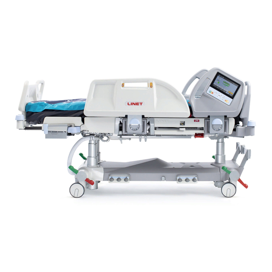
4 Product Description Fig. Bed Overview (Multicare X) Multiboard X Removable Head Board Head Siderail Four-part Mattress support platform with Ergoframe® System Foot Siderail with Patient Control Panels Removable Foot Board (lockable) Corner Bumper Foot Board Safety Lock (unlocked) Foot Board Safety Lock (locked) -
Page 23: Technical Specification
5 Technical Specification All technical data are rated data and are subject to construction and manufacturing tolerances. WARNING! If Multicare X bed is used with OptiCare X integrated mattress system respect values of mechanical and elect- rical specifications which can harm none of them! 5.1 Identification of Applied Parts (Type B) All part of the bed (and accessories) the patient can reach are type B Applied Parts. -
Page 24: Environment Conditions (Multicare X)
Version 110 V 2 x T4.0A L 250 V Version 100 V 2 x T4.0A L 250 V NOTE Upon request, LINET ® can deliver hospital beds with electrical specifications that comply with regional standards (custom voltage, different mains plugs). D9U001MCX-0101_03... -
Page 25: Electromagnetic Compatibility
5.6 Electromagnetic Compatibility Bed is intended for hospitals except for near active HF surgical equipment and the RF shielded room of a medical system for magnetic resonance imaging, where the intensity of EM disturbances is high. Bed has defined no essential performance. WARNING! Use of this equipment adjacent to or stacked with other equipment should be avoided because it could result in improper operation. -
Page 26: Manufacturer Instructions - Electromagnetic Susceptibility
5.6.2 Manufacturer instructions - electromagnetic susceptibility Immunity Tests Compliance level Electrostatic discharge (ESD) ± 8 kV for contact discharge IEC 61000-4-2 ± 15 kV for air discharge Radiated RF 3 V/m IEC 61000-4-3 80 MHz – 2,7 GHz 80 % AM at 1 kHz Proximity fields from RF wireless communications equipment IEC 61000-4-3 See Table 1... -
Page 27: Available Connectors
(i.e. mobile phones, tablets). only for charging! rails) 5) Plug&Play for Atten- Special connection for optional wired Connect only the LINET Attendant Control Panel compati- dant Control Panel (left ACP for bed control (intended for nurse). ble with Multicare X! bed side) 6) Plug&Play for Hand-... -
Page 28: Use And Storage Conditions
► Use exclusively Hospital Grade or Hospital Only receptacles for grounding. Multicare X and OptiCare X are designed for use in rooms for medical purposes. Electrical installations must therefore meet local norms laying down the necessary conditions for electrical installations. -
Page 29: Scope Of Delivery And Bed Variants
Notify the carrier and supplier of any deficiencies or damages immediately as well as in writing or make a note on the delivery note. 7.2 Scope of Delivery ■ Multicare X medical bed ■ Instructions for use 7.3 Multicare X Variants Variable bed features: ■... -
Page 30: Putting Into Service
If there is a considerable temperature difference between the bed and the place of operation (after transport/sto- rage), leave bed unconnected for 24 hours for the difference to balance itself. NOTE For safe, easy handling, LINET ® recommends having two technicians put the bed into service. Set up the bed as follows: ►... -
Page 31: Accumulator Activation
8.1 Accumulator Activation Control Section Placement Fig. Isolating Foil Placement Removing the Isolating Foil To remove isolating foil: ► Remove isolating foil from mains control box by pulling strap. ► Check if isolating foil is complete and undamaged as shown in figure Detail of Isolating Foil. ►... -
Page 32: Foot Board
8.2 Foot Board Dismount the foot board as follows: ► Unlock both foot board locks. ► Pull foot board from sleeve fittings. ► Lock foot board locks. Install the foot board as follows: ► Unlock foot board locks. ► Slide foot board into sleeve fittings. ►... -
Page 33: Head Board
Nurse Call hospital system) 4. Mains Power Cable Fig. Head Board 8.4 Mattress Support Platform Multicare X bed has 4-part Mattress support platform consisting of Backrest, Seat section, Thighrest and Calfrest. LEFT SIDE RIGHT SIDE Fig. 4-part Mattress support platform... -
Page 34: Potential Equalisation
8.5 Potential Equalisation The bed is equipped with a standard protective connector. This connector is used for potential equalisation between the bed and any intravascular or intracardiac device connected to the patient to protect the patient from static electric hocks. Fig. -
Page 35: Before Use
8.6 Before Use Prepare the bed for use as follows: ► Connect the bed to the mains. ► Charge the accumulator. ► Raise and tilt the mattress support platform to the highest position. ► Lower and tilt the mattress support platform to the lowest position. ►... -
Page 36: Firmware
Fig. Bed Transport Mode (Attendant Control Panel) 8.8 Firmware The bed includes firmware that can be updated only by an authorised service technician. This firmware is protected against unauthorised access by mechanical housing (tool is needed to access), by seal (com- ponents with processor are sealed), by exclusive compatibility with an authorised software tool and by check of compati- bility of the new firmware with the bed. 9 Power Cord Attachment plug is means of connecting and disconnecting bed from the mains. Mains power cord must be attached with a hook at the head end of the bed during transport. -
Page 37: Accumulator
10 Accumulator WARNING! When the bed is not connected to the mains and accumulator is not sufficiently charged all electrical func- tions of the bed are blocked! After some long period without charging the battery, the battery will be deeply discharged and loose its full functionality! Purpose The accumulator serves as a backup during power failures or for emergency bed positioning. ►... -
Page 38: Replacing The Accumulator
10.1 Replacing the accumulator CAUTION! Damage to the bed due to incorrect accumulator replacement! ► Have the accumulator replaced exclusively by qualified personnel. ► Exclusively use the accumulator approved by the manufacturer. CAUTION! Material damage due to overheating! If the accumulator is faulty, degassing may occur. In rare cases this might cause deformations of the accumulator case, control panel housing or cable. -
Page 39: Manipulation
11 Manipulation WARNING! Risk of injury when adjusting the bed! ► Ensure that there are no body parts between the mattress support platform elements and the mattress support platform frame when adjusting the bed. ► Ensure that there are no body parts below the mattress support platform frame before adjusting the bed. 11.1 Siderails The split siderails are components of the bed in contact with patient. -
Page 40: Castor Control
11.2 Castor Control CAUTION! Material damage due to incorrect transport and involuntary movement! ► Prior to transport, ensure that the bed is disconnected from the mains. ► Ensure that the castors are braked prior to assembly, disassembly and maintenance. ► Ensure that the castors are braked when the bed is occupied. -
Page 41: Cpr Backrest Release
11.3 CPR Backrest Release WARNING! Risk of injury due to lowering the backrest too quickly! ► Ensure that the siderails are in the low position. ► Ensure that there are no body parts between any movable parts of the bed. ►... -
Page 42: Control Elements
12 Control Elements The bed is operated by different control elements. Control elements depending on the model: ■ Multiboard X with LCD touchscreen in both head siderails ■ Attendant Control Panel ■ Handset with illuminated buttons and with adapter for easy connection (Plug and Play) ■... -
Page 43: Multiboard X
12.1 Multiboard X The Multiboard X is the main control element for the caregivers. It consists of LCD touchscreen and keyboard and it is integrated in the outside of both head siderails. ► Ensure that exclusively trained nursing staff operates the Multiboard X. 1. -
Page 44: Home Screen (Lcd Touchscreen)
12.1.1 Home Screen (LCD touchscreen) The LCD touchscreen is a part of the Multiboard X integrated in the head siderail. Depending on the current function, the LCD touchscreen shows different screens. Each selected screen displays a status bar in the top and a menu bar in the bottom. 22:58 25. - Page 45 ACCUMULATOR CHARGE STATUS WARNING! Disabled functions due to critically discharged accumulator! ► Connect bed immediately to the mains. Accumulator Charge Status is indicated by the icon in the upper right corner of each screen on LCD touchscreen. Acummulator Charge Status Indication Charging Charged Accumulator...
- Page 46 TILES ON THE HOME SCREEN Tile Meaning BACKREST ANGLE IS IN 30° (GREEN UPPER PART OF FIGURE = BACKREST ANGLE IN MORE THAN 30° OR EQUAL TO 30°) POSITIONING BED IS IN THE MINIMUM HEIGHT (GREEN COLUMNS ON BED PICTURE = BED IS IN THE MINIMUM HEI- 30°...
- Page 47 Tile Meaning BED IS OVERLOADED SCALES BED IS UNDERLOADED SCALES BED EXIT ALARM MONITORING IS ACTIVATED (ON) AND INNER ZONE BED EXIT ALARM MONITORING IS SELECTED BED EXIT ALARM MONITORING IS ACTIVATED (ON) AND OUTER ZONE BED EXIT ALARM MONITORING IS SELECTED BED EXIT ALARM MONITORING IS DEACTIVATED (OFF) BED EXIT ALARM BED EXIT ALARM MONITORING IS PAUSED (COUNTDOWN INDICATES...
- Page 48 Tile Meaning TRIGGERED BED EXIT ALARM (PATIENT IS NOT IN REQUIRED POSITI- BED EXIT ON ON THE BED DURING ACTIVATED BED EXIT ALARM MONITORING) ALARM BED EXIT ALARM MONITORING IS TURNED OFF BECAUSE OF THE BED DISCONNECTED FROM THE MAINS POWER BED EXIT ALARM STAND-BY AUTOMATIC LATERAL THERAPY IS NOT ACTIVATED...
- Page 49 Tile Meaning INTEGRATED MATTRESS IS DISCONNECTED (AT LEAST ONE AIR HOSE MATTRESS IS DISCONNECTED FROM SCU) INTEGRATED MATRESS ERROR, CORRESPONDING POP-UP WINDOW IS DISPLAYED ON THE INTEGRATED MATTRESS SCREEN (CONTACT MATTRESS SERVICE DEPARTMENT OF THE MANUFACTURER) INTEGRATED MATTRESS CONTROL IS DISABLED (INTEGRATED MATTRESS MATTRESS IS DISCONNECTED FROM THE MAINS POWER) STAND-BY...
- Page 50 Tile Meaning INTEGRATED MATTRESS RUNS IN PRONE MODE (TIME INDICATES MATTRESS HOW LONG PATIENT LIES PRONE) PRONE 0:15:00 INTEGRATED MATTRESS RUNS IN MAX MODE (COUNTDOWN INDICA- MATTRESS TES MINUTES REMAINING UNTIL THE END OF MAX MODE) 0:15:00 D9U001MCX-0101_03...
-
Page 51: Statuses (Multiboard X - Lcd Touchscreen)
12.1.2 Statuses (Multiboard X - LCD touchscreen) There are 3 types of pop-up windows according to the coloured stripe in the upper part of pop-up window. Red colour indicates warning with required action. Orange colour indicates caution with recommended action. Grey colour indicates only notification. - Page 52 Status (Pop-up window) Meaning How to change the status Use Lateral Tilt with siderail Lateral Tilt with siderail folded down is MAX 15° folded down to facilitate patient limited to 15°. Transfer Mode is activated. transfer. Transfer mode active. Lateral tilt limited to 15°. Use LCD touchscreen on Mul- Lateral Tilt that can be adjusted by pedals tiboard X or Attendant Control...
- Page 53 Status (Pop-up window) Meaning How to change the status Deactivate the running Automatic Positioning is disabled during activated Lateral Therapy if bed positioning Automatic Lateral Therapy. is needed. Positioning disabled during ALT. Remove the obstacle from the Lowering of the mattress support platform undercarriage cover to continue is stopped because of a detected ob- in lowering the mattress support...
- Page 54 Multicare X bed. Bed tilted. OPTIMIZE Mode. OPTIMIZE function not available. Raise all siderails up to enable...
- Page 55 Status (Pop-up window) Meaning How to change the status Bed reached horizontal position. Position bed if needed. Horizontal position reached. Confirmation window of a time change or Press TICK for confirmation or of an overwriting the scales history. CROSS for cancel. Confirm overwriting? Maximum Backrest Angle was reached Change the Backrest Angle ad-...
- Page 56 Care X mattress! Mattress disconnected. Use manual CPR. B111 Stop using the Multicare X bed SERVICE System fault of the Multicare X bed! and contact service department approved by manufacturer! System fault. Stop using bed. Call service. B202 Scales system is disconnected and its...
- Page 57 Status (Pop-up window) Meaning How to change the status P100 OptiCare X integrated mattress does not Connect the bed to the mains work because of the bed disconnected power to enable functions of the from the mains power. OptiCare X integrated mattress! Bed disconnected.
- Page 58 Status (Pop-up window) Meaning How to change the status P108 Press MUTE Icon to mute acous- tic alert sounding from SCU. Optimization process has been stopped Position the patient to the centre because patient is not properly placed on of the mattress support platform the OptiCare X integrated mattress.
-
Page 59: Fault Codes (Opticare X Integrated Mattress)
12.1.3 Fault Codes (OptiCare X integrated mattress) Fault Code Type of the Fault Immediate Action of Operator Corrective Action of Operator Check both manual CPR valves for closing. If problem is still present, Major Inflate Fault Check air connections to SCU. contact service department (air leak) If problem is still present, transfer patient to... -
Page 60: Settings Screens
12.1.4 Settings Screens 22:58 25. 12. 25 30° NEW PATIENT 12° 7° PATIENT CONTROLS AND UNDERCARRIAGE LIGHTS Fig. Settings Menu 1. Settings Icon (to enter Settings Screen) 2. Settings Screen Icon (to enter Settings Menu of the selec- ted screen) 3. - Page 61 3 SETTING SCREENS 22:58 25. 12. 25 SETTINGS DATE TIME MONTH YEAR HOUR 2050 DATE TIME YY/MM/DD MM/DD/YY DD. MM. YY AM/PM 24 h FORMAT FORMAT LANGUAGE ENGLISH Fig. Settings Screen 1 1. DATE Settings Icons (day/month/year) 2. DATE FORMAT Settings Icons (year/month/day or month/day/year or day. month. year) 3.
- Page 62 22:58 25. 12. 25 SETTINGS SCALES DISCREET MODE HOME SCREEN RETURN IN HIDE PATIENT WEIGHT SLEEP MODE MEDIUM UNITS DISPLAY BACKLIGHT MATTRESS OPTIMIZE MODE - COMFORT ADJUSTMENT PUMP LOG OUT Fig. Settings Screen 2 1. Home Screen Return Settings Icon (countdown in minutes before the automatic return from the selected screen to the Home Screen) 2.
-
Page 63: New Patient Function
Fig. Settings Screen 3 (insert password to enter Service Settings) 12.1.5 NEW PATIENT FUNCTION NEW PATIENT PATIENT CONTROLS AND It is recommended to use New Patient function when replacing patients and no patient lies on the Multicare X bed. UNDERCARRIAGE LIGHTS The New Patient function has following eff ects on the Multicare X bed with OptiCare X integrated mattress: ■... - Page 64 NEW PATIENT GUIDE Order of the NEW PATIENT Guide steps Signalisation & Settings Ensure the following conditions are met: ► Patient is not in bed. NEW PATIENT – RESET BED DATA ► Scales are stabilized. • The patient can not be in bed •...
- Page 65 Cancelling the NEW PATIENT function Signalisation & Settings To cancel the NEW PATIENT function: ► Press Cross Icon on the corresponding NEW PATI- ENT Guide window. NEW PATIENT PROCESS INTERRUPTED Start the process again See the window displayed in the case of the interrupted NEW PATIENT function on the right side.
-
Page 66: Positioning Screen (Lcd Touchscreen)
12.1.6 Positioning Screen (LCD touchscreen) 22:58 25. 12. 25 30° 12° 7° Fig. Positioning Screen - LCD touchscreen 1. Mobilization Position Icon 2. Cardiac Chair Position Icon 3. Calfrest Adjustment Icons (UP/DOWN) 4. Bed Extension Icons (LONGER/SHORTER) 5. Longitudinal Tilt Icons (UP/DOWN) 6. - Page 67 COMBINED TILT POSITIONING Combined Positioning Screen enables less limited simultaneous positioning of the Lateral Tilt and of the Longitudinal Tilt (Trende- lenburg Tilt and Antitrendelenburg Tilt). A corresponding pop-up window indicates the reached tilt adjustment limits of the bed. 22:58 12°...
- Page 68 HISTORY OF BACKREST POSITIONS 22:58 25. 12. 25 30° NEW PATIENT 12° 7° PATIENT CONTROLS AND UNDERCARRIAGE LIGHTS Fig. Settings Menu of the Positioning Screen 1. Settings Icon (to enter Settings Screen) 2. Settings Screen Icon (to enter Settings Menu of the selected screen) 3.
- Page 69 22:58 25. 12. 25 DATE TIME ≥30° TIME ≥45° BACKREST 25. 12. 2025 10:00:00 03:30:00 HISTORY 24. 12. 2025 08:42:00 03:30:00 23. 12. 2025 09:00:00 03:30:00 22. 12. 2025 18:30:00 03:30:00 21. 12. 2025 06:00:00 03:30:00 20. 12. 2025 00:00:00 03:30:00 19.
-
Page 70: Lock Screen (Lcd Touchscreen)
12.1.7 Lock Screen (LCD touchscreen) 22:58 25. 12. 25 Fig. Lock Screen - LCD touchscreen 1. Patient Control Elements Lock Icon (Patient Control Panels in foot siderails, Handset, Mobi-Lift) 2. Thighrest and Calfrest Lock Icon 3. Height and Tilt Lock Icon (Bed Height, Trendelenburg Tilt, Antitrendelenburg Tilt, Lateral Tilt) 4. -
Page 71: Attendant Control Panel
12.2 Attendant Control Panel The Attendant Control Panel is a standard Control Element. The Attendant Control Panel can be hung on the foot board or on side- rails if required. It is possible to hold the Attendant Control Panel in the hand while operating. ►... - Page 72 GO BUTTON The button activates the keyboard of all control elements for 3 minutes, except for Lateral Tilt Foot Control. During this time the following is possible: ► Adjusting individual mattress support platform elements by pressing the corresponding function buttons. ►...
-
Page 73: Bed And Keyboards Illumination
Bed and Keyboards Illumination helps the nursing staff as well as the patient to orientate. The illumination is turned off when the bed is powered by accumulator. The Multicare X bed is equipped with three-phase illumination: 1. Full intensity of illumination 2. -
Page 74: Handset (Optional)
12.3 Handset (optional) The handset is available with illuminated keyboard. The illumination is activated for 7s if any button was pressed and the illumination is activated for 3 minutes if GO Button was pre- ssed. 1. Thighrest Adjustment Buttons 2. Thighrest/Backrest Lock LED 3. -
Page 75: Patient Control Panels
12.4 Patient Control Panels The Patient Control Panels integrated in the foot siderails allow the patient to adjust the positions of the Backrest, Thighrest and Autocontour. 1. GO Button (activation of the control panel) 2. Backrest Adjustment Button – UP 3. -
Page 76: Bed Height Foot Control (Optional)
12.5 Bed Height Foot Control (optional) The foot control is optional and allows setting the bed height with one’s feet. The use of Bed Height Foot Control is described in the chapter „13 Bed Positioning“ on the page 77. Press the selected pedal twice in 3 seconds: ►... -
Page 77: Bed Positioning
13 Bed Positioning 13.1 Backrest 22:58 25. 12. 25 To position Backrest use: ► Multiboard X 30° ► Attendant Control Panel ► Handset ► Patient Control Panel (in foot siderail) 12° 7° Multiboard X Positioning Screen shows Backrest Angle. Fig. Backrest Angle on Multiboard X Display During continuous positioning Backrest stops automatically in 30 and 45 degrees (the beep will appear). -
Page 78: Thighrest
Patient Control Panel (in foot siderail): ► Press button ► Press selected Backrest Adjustment Button until inten- ded position is reached. Fig. Backrest Adjustment Buttons (Patient Control Panel) Attendant Control Panel: ► Press button ► Press selected Backrest Adjustment Button until inten- 1. - Page 79 To position Thighrest use: ► Multiboard X ► Attendant Control Panel ► Handset ► Patient Control Panel (in foot siderail) Multiboard X: ► Press button ► Press selected Thighrest Adjustment Button until intended position is reached. Fig. Thighrest Adjustment Buttons (Multiboard X) Patient Control Panel (in foot siderail): 1.
-
Page 80: Calfrest
13.3 Calfrest 22:58 25. 12. 25 To position Calfrest position Thighrest firstly. 30° To position Calfrest use: ► Multiboard X ► Attendant Control Panel 12° 7° Multiboard X: ► Press button ► Press selected Calfrest Adjustment Button until intended position is reached. Fig. Calfrest Adjustment Buttons (Multiboard X) 1. -
Page 81: Bed Height
13.4 Bed Height To position Bed Height use: ► Multiboard X ► Attendant Control Panel ► Handset ► Bed Height Foot Control ► Mobi-Lift Multiboard X: ► Press button ► Press selected Bed Height Adjustment Button until inten- ded position is reached. 1. -
Page 82: Autocontour
Handset: ► Press button ► Press selected Bed Height Adjustment Button until intended position is reached. 1. Mattress Support Platform Up 2. Matress Support Platform Down Fig. Bed Height Adjustment Buttons (Handset) Bed Height Foot Control: ► Press the selected Bed Height Pedal and release it. ►... - Page 83 To position Autocontour use: ► Multiboard X ► Handset ► Patient Control Panel (in foot siderail) Multiboard X: ► Press button ► Press selected Autocontour Adjustment Button until intended position is reached. Fig. Autocontour Adjustment Buttons (Multiboard X) 1. Autocontour 2.
-
Page 84: Emergency Trendelenburg Position
13.6 Emergency Trendelenburg Position Fig. Trendelenburg Position Trendelenburg position provides anti-shock conditions for the patient. During Trendelenburg Position Mattress support platform is straightened in the tilt. To position Emergency Trendelenburg Position use: ► Multiboard X ► Attendant Control Panel WARNING! Risk of injury due to improper use of Trendelenburg Position! ►... -
Page 85: Antitrendelenburg And Trendelenburg Tilt
13.7 Antitrendelenburg and Trendelenburg Tilt 22:58 25. 12. 25 30° Fig. Antitrendelenburg Tilt 22:58 To position Trendelenburg or Antitrendelenburg Tilt use: 12° 25. 12. 25 ► Multiboard X ► Attendant Control Panel 7° Multiboard X touchscreen shows Longitudinal Tilt Angle. 30°... -
Page 86: Examination Position
Attendant Control Panel: ► Press button ► Press selected Longitudinal Tilt Button until intended position is reached. Fig. Longitudinal Tilt Buttons (Atten- dant Control Panel) 1. Antitrendelenburg Tilt 2. Trendelenburg Tilt 13.8 Examination Position To position Examination Position use: ► Bed Height Foot Control Bed Height Foot Control: ►... -
Page 87: Bed Extension
13.9 Bed Extension 22:58 25. 12. 25 30° To position Bed Extension use: ► Multiboard X 12° ► Attendant Control Panel 7° Multiboard X: ► Press button ► Press selected Bed Extension Adjustment Button until intended position is reached. Fig. Bed Extension Adjustment Buttons (Multiboard X) 1. -
Page 88: Cpr Position
13.10 CPR Position In CPR Position bed reaches flat Mattress support platform. If the bed is equipped with OptiCare X mattress, pressing CPR Button will also deflate the mattress. To position CPR Position use: ► Multiboard X ► Attendant Control Panel Multiboard X: ► Press CPR Position Button until intended position is reached. Fig. CPR Button (Multiboard X) Attendant Control Panel: ► Press CPR Position Button until intended position is reached. Fig. -
Page 89: Cardiac Chair Position
13.11 Cardiac Chair Position To position Cardiac Chair Position use: ► Multiboard X ► Attendant Control Panel Multiboard X: ► Press button ► Press Cardiac Chair Position Button until intended position is reached. Fig. Cardiac Chair Position Button (Multiboard X) Attendant Control Panel: ►... -
Page 90: Lateral Tilt
13.12 Lateral Tilt Fig. Lateral Tilt Angle on Multiboard X Display It is not possible to position Lateral Tilt with a siderail folded down without use of an additional function. To position Lateral Tilt use: ► Multiboard X ► Lateral Tilt Foot Control ►... - Page 91 Multiboard X: ► Press button ► Press Lateral Tilt Button until intended position is reached. Fig. Lateral Tilt Buttons (Multiboard X) Lateral Tilt Foot Control: ► Press the selected Lateral Tilt Pedal and release it. ► Press and hold selected Lateral Tilt Pedal once more until intended position is reached.
-
Page 92: Vascular Position
13.13 Vascular Position In Vascular Position Thighrest and Calfrest are lifted up to lift up patient´s legs. To position Vascular Position use: ► Multiboard X Multiboard X: ► Press button ► Press Vascular Position Icon until intended position is reached. Fig. -
Page 93: Mobilisation Position
13.14 Mobilisation Position In Mobilisation Position bed is descending to the lowest Bed Height and Backrest reaches the maximum angle. To position Mobilisation Position use: ► Multiboard X Multiboard X: ► Press button ► Press Mobilisation Position Button until intended position is reached. -
Page 94: Low Flat Position
13.15 Low Flat Position In Low Flat Position the mattress support platform is firstly adjusted to flat position without any lateral tilt and then lo- wered to the minimum height. To position Low Flat Position use: ► Lateral Tilt Foot Control Lateral Tilt Foot Control: ► Press Low Flat Position Pedal and release it. ► Press and hold Low Flat Position Pedal once more until intended position is reached. -
Page 95: Scales Control
14 Scales Control Multicare X is equipped with a weighing system that allows weighing the patient in bed. The control and display elements for the weighing system are situated on the Scales screen on the Multiboard X LCD touchscreen. 22:58 25. - Page 96 To tare weight: ► Ensure that nothing and nobody touches the bed except you. ► Press and hold ZERO/T Icon. ► Follow Guide for Taring. To cancel Taring: ► Press Cross Icon on the corresponding window of the Guide for Taring. GUIDE FOR TARING Order of the Guide for Taring steps Signalisation &...
-
Page 97: Displaying
14.3 Displaying Weight Value Indicator (1) displays the calibrated and metrological certifi ed weight value. Verifi cation Scale Interval is 0,5 kg. To change scale interval: ► Press Scale Interval Switch Icon with 0,1 (3) to display value with actual scale interval 0,1 kg. 14.4 Hold Mode Hold Mode can be used only when scales are stabilized. - Page 98 HOLD MODE GUIDE Order of the HOLD Mode Guide steps Signalisation & Settings Ensure the following condition is met: ► Scales are stabilized. DO YOU WANT TO HOLD THE SCALES TO ATTACH / REMOVE ACCESORIES? To start HOLD Mode setting: (Do not Attach / Remove accessories in this step) Press Tick Icon.
-
Page 99: Bed Overload
Cancelling the HOLD Mode Signalisation & Settings To cancel the HOLD Mode: ► Press Cross Icon on the corresponding HOLD Mode Guide window. HOLD MODE Attach / Remove all required accessories. See the window displayed in the case of the interrupted HOLD Mode setting on the right side. -
Page 100: Bed Underload
B123 >250 kg Bed overloaded. Remove load from the bed. Fig. Overloaded bed (warning pop-up window) 14.6 Bed Underload If the bed is underloaded: ► Display shows „Lo“. 22:58 25. 12. 25 CURRENT WEIGHT Max 250 kg, Min 10 kg, e = 0,5 kg ZERO Fig. -
Page 101: Weighing In Tilt
Factory Zero Setting is done after installation, weight verifi cation or servicing. Only authorised and trained service technician is allowed to change the factory zero setting in the Service Settings. Guide for Fac- tory Zero Setting is described in Service Manual for Multicare X. 14.9 History of Weight Values 22:58 25. -
Page 102: New Patient Function
15 Bed Exit Alarm Monitoring (only version with scales) Multicare X bed is equipped with a Bed Exit Alarm Monitoring system that monitores patient´s presence in bed and triggers alarms when patient is not present in bed in ordered position. Enter Bed Exit Alarm Monitoring Screen by pressing Bed Exit Alarm Monito- ring Screen Icon on Multiboard X LCD touchscreen to control the Bed Exit Alarm Monitoring functions. -
Page 103: Activation
15.2 Activation 22:58 25. 12. 25 BED EXIT IS Bed Exit Alarm Monitoring Screen Icon Fig. Bed Exit Alarm Monitoring Screen (OFF) ON Icon (activation) To enter Bed Exit Alarm Monitoring Screen: ► Press Bed Exit Alarm Monitoring Screen Icon (1). To activate Bed Exit Alarm Monitoring: ►... -
Page 104: Bed Exit Alarm Monitoring Screen
15.3 Bed Exit Alarm Monitoring Screen 22:58 25. 12. 25 ZONE Fig. Bed Exit Alarm Monitoring Screen Bed Picture (Patient Picture is displayed when mattress support platform is loaded by more than 35 kg.) Inner Zone Icon Outer Zone Icon ON Icon (activation) OFF Icon (deactivation) PAUSE Icon... -
Page 105: Pause
15.5 PAUSE During PAUSE mode the Bed Exit Alarm Monitoring is temporarily interrupted and alarms are not activated. PAUSE period is terminated automatically and the Bed Exit Alarm Monitoring is reactivated again when patient returns just to the selected zone. To PAUSE Bed Exit Alarm Monitoring: ►... -
Page 106: Bed Exit Alarm
15.6 BED EXIT ALARM Audible alarm is triggered when patient has left selected monitored zone or when PAUSE period is terminated and patient is not just in the ordered position. During this alarm a text „BED EXIT ALARM“ in a red rectangle is displayed on the Bed Exit Alarm Moni- toring Screen. -
Page 107: Deactivation
15.7 Deactivation To deactivate Bed Exit Alarm Monitoring: ► Press OFF Icon (5). ► Press Tick Icon on the following window to confi rm deactivation of the Bed Exit Alarm Monitoring. Text “BED EXIT IS OFF” in a yellow fi eld is displayed on the touchscreen. DO YOU WANT TO STOP BED EXIT ALARM? Fig. -
Page 108: Automatic Lateral Therapy (Alt)
► Ensure that siderails are folded up. ► Always use LINET ® Stabilising ALT Pads or Advanced Stabilising ALT Pads for positioning patient in middle of the bed. ► Always use LINET ® Ventilation Circuit Holder to prevent extubation. ►... -
Page 109: Initial Alt Screen
16.1 Initial ALT Screen Values of periods and angles in the selected Preset ALT Program are changed when they are changed manually and saved in the selected Preset ALT Program. 22:58 25. 12. 25 30° 15° 0° 15° 30° 15° 0°... -
Page 110: Description Of Alt Screen
16.2 Description of ALT Screen 22:58 25. 12. 25 22:58 25. 12. 25 0:30 0:30 2:00 2:00 2:00 2:00 2:00 2:00 2:00 2:00 12° 0:30 0:30 0° 2:00 2:00 2:00 2:00 15° 15° 2:00 2:00 2:00 2:00 12° 25° 25° 26°... -
Page 111: Bed Collisions With The Environment
16.3 Bed collisions with the environment 22:58 25. 12. 25 22:58 25. 12. 25 0:30 0:30 1:30 1:30 1:30 1:30 2:00 2:00 2:00 2:00 12° 0:30 0:30 2:00 2:00 0° 2:00 2:00 15° 15° 2:00 2:00 2:00 2:00 12° 30° 30°... - Page 112 To adjust Lateral Tilt Angle: ► Press selected Indicator of Lateral Tilt Angle. ► Press MINUS Icon (1) or PLUS Icon (2). ► Press selected Indicator of Lateral Tilt Angle once more or press another Indicator of Lateral Tilt Angle. Selected Lateral Tilt Angle is changed.
-
Page 113: Test Of The Automatic Lateral Therapy
Press TEST Icon (1). Multicare X bed will reach horizontal position and then it will be successively adjusted to each position of the preset Automatic Lateral Therapy. TEST of the Automatic Lateral Therapy ends in the bed horizontal position. Initial direction of the TEST is always to the right from the perspective of a patien lying on the bed. -
Page 114: Activated Automatic Lateral Therapy
16.6 Activated Automatic Lateral Therapy 22:58 25. 12. 25 0:30 0:30 2:00 2:00 2:00 2:00 22:58 2:00 2:00 2:00 2:00 0° 0° 25. 12. 25 15° 15° 15° 15° 25° 25° 25° 25° 26° 12° 0:30 0:30 2:00 2:00 2:00 2:00 2:00 2:00... -
Page 115: Paused Automatic Lateral Therapy
16.7 PAUSED Automatic Lateral Therapy 22:58 25. 12. 25 PAUSE 22:58 0:30 0:30 25. 12. 25 2:00 2:00 2:00 2:00 2:00 2:00 2:00 2:00 12° 0:30 0:30 0° 0° 2:00 2:00 2:00 2:00 15° 15° 15° 15° 2:00 2:00 2:00 2:00 12°... -
Page 116: Return To The Bed Position Before Pause
16.8 Return to the bed position before PAUSE 22:58 25. 12. 25 PAUSE 22:58 0:30 0:30 25. 12. 25 2:00 2:00 2:00 2:00 2:00 2:00 2:00 2:00 12° 0:30 0:30 0° 0° 2:00 2:00 2:00 2:00 15° 15° 15° 15° 2:00 2:00 2:00... -
Page 117: History Of Alt Cycles
16.9 History of ALT Cycles 22:58 25. 12. 25 22:58 25. 12. 25 0:30 0:30 0:30 2:00 2:00 2:00 2:00 2:00 2:00 12° 0:30 0:30 2:00 2:00 2:00 2:00 0° 0° 15° 15° 15° 2:00 2:00 2:00 2:00 12° 25° 25°... - Page 118 22:58 25. 12. 25 DATE PROGRAM TIME CYCLES HISTORY Fig. ALT Cycles History Screen 1. Column with recorded dates 2. Column with recorded used ALT Programs 3. Column with recorded periods during which the selected ALT Program was running 4. Column with numbers of cycles performed during the selected ALT Program 5.
-
Page 119: Equipment
17 Equipment Product equipment depends on product configuration so the equipment is always optional. 17.1 Accessory Rail with plastic hooks Accessory Rail with 2 plastic hooks is intended for hanging accessories. It is located on the sides of bed. Fig. Accessory Rail (on the sides of bed) D9U001MCX-0101_03... -
Page 120: Brake Signal
17.5 LINIS SafetyPort LINIS SafetyPort is a medical device data system for capturing and transferring data from LINET beds into SafetyPort Dashboard and third party systems, including nurse calls, EHR and digital whiteboards. Data collection and evaluation takes place at one central location for all beds connected to the system simultaneously. -
Page 121: Undercarriage
17.6 Undercarriage CAUTION! Risk of material damage due to objects on the undercarriage cover! ► Do not place objects on the undercarriage cover! Fig. 3-part undercarriage cover Fig. 1-part undercarriage cover D9U001MCX-0101_03... -
Page 122: I-Drive Power
17.7 i-Drive Power 17.7.1 i-Drive Power System - Basic Description It is possible to equip the bed with the i-Drive Power wheel. The i-Drive Power helps hospital staff to drive the bed during patient transport with minimal manpower. The i-Drive Power wheel is located in the center of the bed under the undercarriage. i-Drive Power is equipped with its own accumulator and charger and it is not dependent on the bed functions so, if discharged you can still use the bed functions. -
Page 123: Manipulation
Each bed can transport only single patient at a time and cannot be used to transport other items (except bed accessories in secured position). NOTE For information concerning uses other than those outlined in the “Specifications of Use” section above, please contact LINET ®. 17.7.4 Manipulation CAUTION! Damage to i-Drive Power main control panel cable due to wrong cable placement! ►... -
Page 124: I-Drive Power Activation/Deactivation
Fig. Activation Panel (4) 5. ON Button (i-Drive Power Wheel Activation Button) 6. OFF Button (i-Drive Power Wheel Retraction and Deactivation Button) 7. GO LED 8. Fault LED 9. State of charge and Fault LEDs 10. REVERSE Button 11. FORWARD Button 12. -
Page 125: Powered Drive
1. i-Drive Power Mains Switch 2. i-Drive Power Emergency Retraction Button Fig. i-Drive Power Emergency Retraction Button Label Fig. i-Drive Power Mains Switch with Label 17.7.6 Powered Drive CAUTION! Damage to property due to incorrect transport and involuntary movement! ► Prior to transport, ensure that the bed is disconnected from the mains. -
Page 126: Braking
NOTE i-Drive Power is not designed for ascending or descending a slope greater than 6° or longer than 20 m. The support of personnel is needed when ascending or descending with a full SWL. NOTE When i-Drive Power wheel is lowered, it is not possible to move the bed sideways. Press the button to retract the wheel, release the castors to the neutral position and then move the bed to any direction required. -
Page 127: Fault Signalization
17.7.10 Fault Signalization The system is protected against failure states, by stopping and braking the drive system, and respective signalization. The fault indicator flashing briefly and the accumulator indicator shows the fault state. Some defects are cleared automatically (e.g.: drive overheating). -
Page 128: Electrical Specification
17.7.13 Electrical specification Parameter Value Input Voltage, Frequency 230 V AC, 50/60 Hz 127 V AC, 50/60 Hz 120 V AC, 50/60 Hz 110 V AC, 50/60 Hz 100 V AC, 50/60 Hz Accumulator Voltage 36 V DC, Capacity: 9 Ah Maximum Power Input 300 W Fuse... -
Page 129: Mobi-Lift
17.8 Mobi-Lift ® WARNING! Risk of injury due to slipping or falling when standing up! ► Ensure that the support handles are completely inserted in the sleeve fittings. ► Ensure that no bed linen is caught between the sleeve fitting and the support handle. Mobi-Lift®... -
Page 130: X-Ray Lung Examination
17.9 X-Ray Lung Examination CAUTION! It is not possible to adjust bed positions unless x-ray cassette holder is correctly inserted to the bed! ► Check regularly if the x-ray cassette holder is correctly inserted to the bed! CAUTION! Prevent x-ray images from being devalued! ►... -
Page 131: Nurse Call
17.10 Nurse Call WARNING! Functions of the Nurse Call system depends on the local hospital information system! ► Ensure the Nurse Call system is compatible with local hospital information system! ► Nurse Call cable running from the local hospital information system must be connected to the connector at head end of the bed! CAUTION! Ability to use the Nurse Call correctly increases patient´s safety! - Page 132 Fig. Speaker and Microphone (inner side of head siderail) Fig. Position of the Nurse Call Connector at head end of the bed) D9U001MCX-0101_03...
-
Page 133: Usb Connector
17.11 USB Connector WARNING! Risk of injury due to incorrect use! ► Ensure accessory pluged in USB connector is in pristine condition! User of the bed is responsible for the fact that this requirement is met. CAUTION! Risk of material damage due to incorrect use! ►... -
Page 134: M-Panel
Intended Use m-Panel is intended to signalize if the safety statuses of Multicare X bed are monitored and if the corresponding alerts are trigge- red in the case of insecure statuses. Monitorable statuses of the bed are: brake status (braked castors/unbraked castors), siderail status (siderails up/siderail down), bed height (bed in the lowest position/bed not in the lowest position) and backrest angle (bac- krest in more than 30°/backrest in less than 30°). -
Page 135: Signalisation (Bed Picture)
17.12.1 Signalisation (Bed picture) 1. siderail status (all siderails up/ siderail down) 2. backrest angle (backrest in more than 30°/backrest in less than 30°) 3. bed height (bed in the lowest position/ bed not in the lowest position) 4. brake status (braked castors/unbraked castors) 5. -
Page 136: Adaptor For Traction Frames
17.13 Adaptor for Traction Frames Multicare X bed is compatible with Traction Frame M and with Traction Frame T41 if bed is equipped with Adaptor for Traction Frames. Fig. Positions to insert Traction Frame M or Traction Frame T41 (undercarriage of Multicare X) 17.14 Safestop... -
Page 137: Mattress
Release the three buckles by pressing them from both sides and by disconnecting their male and female parts. ► Pull these three straps out of the Mattress Support Platform. ► Remove mattress from the Mattress Support Platform. Fig. Fixation of the mattress with straps on the mattress support platform of Multicare X bed D9U001MCX-0101_03... -
Page 138: Passive Mattress
18.2 Passive Mattress Recommended Passive Mattresses are equipped with straps (1) intended for fixing mattress on the Mattress support platform. Fig. Bottom of Passive Mattress 18.3 Active Mattress (not integrated) WARNING! Follow instructions for use of a compatible active mattress carefully! CAUTION! Risk of material damage due to an incorrect fixation of compatible active mattress on the mattress support ... -
Page 139: Integrated Mattress
Do not use any other System Control Unit with OptiCare X mattress! CAUTION! Material damage due to incorrect installation of SCU! ► If the SCU does not come factory-fitted, have it installed by a service engineer authorised by LINET ®. D9U001MCX-0101_03... -
Page 140: Integrated Mattress Screen (Opticare X)
18.4.1 Integrated Mattress Screen (OptiCare X) 22:58 25. 12. 25 ,5 kg RE-OPTIMIZE MICROCLIMATE HIGH OPTIMIZE MOBILE PRONE Fig. Integrated Mattress Screen - LCD touchscreen 1. OPTIMIZE Mode Icon (press to enter OPTIMIZE Mode) 2. MOBILE Mode Icon (press to enter COMFORT Mode) 3. -
Page 141: Accessories
Avoid collisions between accessories and bed parts before use of the accessories! WARNING! Risk of injury or material damage due to incorrect use! ► Compatible accessories manufactured by different manufacturers have their own instructions for use. It is necessary to read instructions for use of a compatible accessory with instructions for use of the compatible LINET product to respect especially technical parameters, warning notifications, cleaning and maintenance instructions of LINET products and their compatible accessories! D9U001MCX-0101_03... - Page 142 Compatible Accessories Identification Numbers Accessory Weight Lifting pole 1101141000000, 11011410A0000, 11011410B0000 with Triangular holder 4ROTGERSG700-2, 4ROTGNR- 100GR-2 with Infusion holder 16010700A0000, 16010700B0000, 4MAPL00N1001, 1101030000000 Infusion Stand 4PKV26107200 0,7 kg with Infusion bottle basket 4DR426101 with Adaptor for infusion stand 4PKV26107200 11029700A0000 Mobile Infusion Stand 4ZZ426100 4 kg...
-
Page 143: Lifting Pole
19.1 Lifting Pole Lifting Pole is intended for supporting a patient who uses it to sit or lift by himself/herself or with the help of a caregiver. To ensure safe use of the lifting pole: ► Never exceed the maximum load of 75 kg. ►... -
Page 144: Triangular Holder For Lifting Pole
19.2 Triangular Holder for Lifting Pole WARNING! Read Instructions for use of the Triangular Holder before use of this product! WARNING! Replace Triangular Holder when this replacement is recommended by its manufacturer! Read Instruc- tions for use of the Triangular Holder before use of this product! Triangular Holder is intended for supporting a patient when lifting the patient on the bed. -
Page 145: Infusion Stand
19.4 Infusion Stand WARNING! Risk of injury due to use of incorrect accessories or because of incorrect use! Infusion Stands must only be used for their intended use. Always read the instructions for use of the corre- sponding infusion stand! ►... -
Page 146: Infusion Bottle Basket For Infusion Stand
19.5 Infusion Bottle Basket for Infusion Stand Infusion Bottle Basket is intended for carrying bottles with intravenous solutions. It is intended to be suspen- ded on Infusion Stand. Maximum Load of the Infusion Bottle Basket is 2 kg. Fig. Infusion Bottle Basket 19.6 Adaptor for Infusion Stand WARNING! Adaptor 11029700A0000 must... -
Page 147: Mobile Infusion Stand
19.7 Mobile Infusion Stand WARNING! Read Instructions for use of the Mobile Infusion Stand before use of this product! Fig. Mobile Infusion Stand with receptacle for cannulas (4ZZ426100) 19.8 Writing Shelf The Writing Shelf is intended for writing of nursing staff. It can be placed only on the foot board as on the following pictures. -
Page 148: Monitor Shelf
19.9 Monitor Shelf The Monitor Shelf is intended for transport of the monitors with a weight of up to 15 kg. Installing the Monitor Shelf: ► Place the Monitor Shelf to the holes in the corner bumpers at foot end. ►... -
Page 149: Utility Shelf
19.10 Utility Shelf Fig. Utility Shelf on the head board The Utility Shelf is intended for linens or sheets. It can be placed on the head board or the foot board. Maximum Load for the Utility Shelf is 10 kg. Fig. -
Page 150: Oxygen Bottle Holders
To place Utility Shelf on head board or foot board: ► Place wire construction on the head board or foot board. ► Insert upper edge of the plastic container under the upper holder of the wire construction as on the picture above. ►... -
Page 151: Vertical Oxygen Bottle Holders
19.11.1 Vertical Oxygen Bottle Holders WARNING! Adaptor 11029700A0000 must be fixed on the head end Accessory Adaptor by the original screw before use! Maximum Load of the properly installed Adaptor 11029700A0000 is 25 kg. Maximum diameter of an oxygen bottle in the Vertical Oxygen Bottle Holders 4MAR2010PC004 and 4MAR2010PC007-1 is 14 cm. Maximum diameter of an oxygen bottle in the Vertical Oxygen Bottle Holder 4MAR2015PC001 is 11 cm. To place Vertical Oxygen Bottle Holders on the bed: ►... -
Page 152: Ventilation Circuit Holder
Both Ventilation Circuit Holders are not compatible with Hercules Patient Repositioner! The ventilation circuit holder prevents extubation of the patient connected to the ventilator. ► Always use LINET ® ventilation circuit holders to prevent extubation during any procedures. Applying ventilation circuit holder: ►... -
Page 153: Urinary Bag Holders
19.13 Urinary Bag Holders CAUTION! Urinary Bag Holder 11023820B0000 is intended only for one urinary bag which is suspended on both hooks of the Urinary Bag Holder! Fig. Urinary Bag Holders 1. Urinary Bag Basket 11023800B0000 2. Urinary Bag Holder 11023820B0000 3. -
Page 154: Handset Holder
Foot Siderail to avoid damaging of the cable during positioning of the bed! Fig. Handset Holder on the Foot Siderail Handle (outer side of the Foot Siderail) 19.15 Positioning Cushion Positioning Cushion provides additional support for a patient during lateral tilting of the Multicare X bed. Fig. Positioning Cushion D9U001MCX-0101_03... -
Page 155: Traction Frame M
WARNING! Risk of injury due to incorrect use! ► Multicare X bed is compatible with Traction Frame M only if the bed is equipped with the Adaptor for Traction Frames! ► There must be no patient on the bed when installing the Traction Frame! ►... -
Page 156: Protectors
The Protector is an optional accessory for the Multicare X bed. The main purpose of the Protector is to reduce the risk of fall espe- cially at very risky patients (confused restless patients). The Protector can be used with extended or standard beds. - Page 157 Fig. Fixing element on the telescopic profile of the bed extension D9U001MCX-0101_03...
-
Page 158: Stabilising Alt Pads
The Stabilising ALT Pads ensure a stable position of the patient during ALT in order to prevent extubation or disconnection of IV lines or other equipment. Always use LINET ® Stabilising ALT Pads for positioning patient in centre of bed during Automatic Lateral Therapy. -
Page 159: Advanced Stabilising Alt Pads
The Advanced Stabilising ALT Pads ensure a stable position of the patient during ALT in order to prevent extubation or disconnec- tion of IV lines or other equipment. Always use LINET ® Advanced Stabilising ALT Pads for positioning patient in the middle of the bed during Automatic Lateral Therapy. -
Page 160: Foldable Iv & Drive (Infusion Stands/Pushing Handles)
19.21 Foldable IV & Drive (Infusion Stands/Pushing Handles) WARNING! Risk of injury due to incorrect placement of an infusion pump! ► Ensure the infusion pump on the Foldable infusion stands will not collide with any movable parts of the Multicare X (especially Backrest) or with the patient! CAUTION! Risk of material damage due to incorrect placement of an infusion pump! - Page 161 FOLD THE FOLD THE MARKED MARKED FOLDABLE FOLDABLE INFUSION INFUSION STAND AS STAND AS THE SECOND THE FIRST ONE. ONE. Fig. Pair of Foldable infusion stands (head end) To fold Foldable infusion stands down: ► Ensure the right Foldable infusion stand is not extended. ►...
- Page 162 To extend Foldable infusion stand: ► Put control ring up (5). ► Extend the Foldable infusion stand by taking its telescopic part out. To shorten Foldable infusion stand: ► Put control ring up (5). ► Insert the telescopic part into the Foldable infusion stand. To prepare hooks of the Foldable infusion stand: ►...
-
Page 163: Cleaning/Disinfection
20 Cleaning/Disinfection WARNING! Risk of injury due to accidental bed movement! ► Always disable the function buttons when cleaning between the undercarriage and mattress support platform. CAUTION! Material damage due to incorrect cleaning/disinfection! ► Do not use washing machines. ► Do not use pressure or steam cleaners. -
Page 164: Cleaning (Multicare X)
■ by the environmental protection agency of the country in which the mattress replacement system is to be used. 20.1 Cleaning (Multicare X) Prepare for cleaning as follows: ►... -
Page 165: Complete Cleaning And Disinfection
20.1.3 Complete Cleaning and Disinfection Clean the following bed parts: ■ All control elements for adjusting the bed ■ All handles □ CPR release handle ■ Head board and Foot board ■ Siderails (in highest position) ■ Freely accessible mattress surface ■... -
Page 166: Troubleshooting
21 Troubleshooting DANGER! Risk of mortal injury due to electric shock! ► If a fault occurs, have the electric motor, power box or other electrical parts repaired by qualified personnel exclu- sively. ► Do not open the protective covers of the electric motor or the power box. Error/Fault Cause Solution... -
Page 167: Maintenance
Ensure that the castors are locked prior to installation, putting into service, maintenance and deinstallation. ► No part of the Multicare X ME equipment shall be serviced or maintained while in use with a patient. WARNING! Risk of injury due to defective bed! ►... -
Page 168: Disposal
Based on the Directive No. 2002/96/ EC (Directive WEEE - Waste, Electric and Electronic Equipments) the company LINET, s. r. o. is registered in the List of Electric and Electronic Equipment Producers (Seznam výrobců elektrozařízení) on the Ministry of the Environment of the Czech Republic... - Page 169 24 Warranty LINET ® will only be held responsible for the safety and reliability of products that are regularly serviced, maintained and used in accordance with the safety guidelines. Should a serious defect arise that cannot be repaired during maintenance: ►...
Need help?
Do you have a question about the Multicare X and is the answer not in the manual?
Questions and answers