
Related Manuals for LINET Multicare


Summary of Contents for LINET Multicare
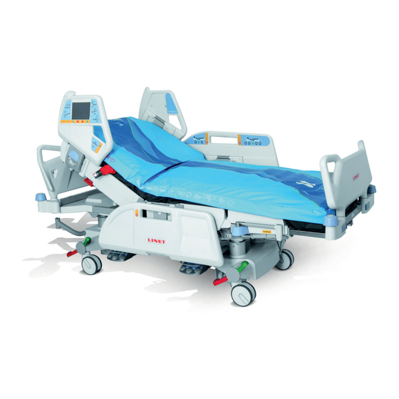
- Page 1 Instructions for Use and Technical Description Multicare Positionable bed for intensive care with scales and without scales D9U001MC0-0101 Version: 16 Publication Date: 2020-02...
- Page 2 Related links: www.linet.com D9U001MC0-0101 Version: 16 Publication date: 2020-02 Copyright © LINET, s.r.o., 2020 Translation © LINET, 2020 All rights reserved. All trademarks and brands are the property of the appropriate owners. The manufacturer reserves the right to changes in the con- tents of the instructions for use that relate to the product´s technical regulations.
-
Page 3: Table Of Contents
5.1 Identification of Applied Parts (Type B) ....... 20 14.2 Activation ..............52 5.2 Scales (only version with scales) ........ 20 14.3 Control of Bed Exit Monitoring ......... 53 5.3 Mechanical Specifications (Multicare) ......20 14.4 Monitored Zone ............53 5.4 Environment Conditions ..........21 14.5 PAUSE ..............53 5.5 Electrical Specifications (Multicare) ...... - Page 4 18.5 Monitor Tray .............67 18.6 Oxygen Bottle Holders ..........68 18.7 Protector ..............69 19 Cleaning/Disinfection ..........70 19.1 Cleaning (Multicare) ..........71 19.1.1 Daily Cleaning ............71 19.1.2 Cleaning before Changing Patients ....... 72 19.1.3 Complete Cleaning and Disinfection ...... 72 20 Troubleshooting ............73 21 Maintenance ...............74...
-
Page 5: Symbols On The Package
1.4 Symbols on the Package FRAGILE, HANDLE WITH CARE THIS WAY UP KEEP DRY (PROTECT FROM HUMIDITY) PAPER RECYCLING SYMBOL DO NOT USE HAND TRUCK HERE DO NOT STACK DURING STORAGE D9U001MC0-0101_16... -
Page 6: Symbols And Labels On The Bed
WARNING ONLY SUITABLE FOR INDOOR USE APPLIED PARTS TYPE B SAFETY ISOLATING TRANSFORMER, GENERAL CE MARK (MULTICARE WITH SCALES) CE MARK (MULTICARE WITHOUT SCALES) JACK FOR ATTACHMENT OF CONDUCTOR FOR POTENTIAL EQUALISATION SAFE WORKING LOAD WARNING AGAINST CRUSHING OR TRAPPING... - Page 7 DO NOT PUT ANY OBJECTS ON UNDERCARRIAGE MAXIMUM WEIGHT OF PATIENT WEIGHT OF BED DESIGNATION OF HOSPITAL BED FOR ADULTS ANTIBACTERIAL SURFACE FINISH WEEE SYMBOL (RECYCLE AS ELECTRONIC WASTE, DO NOT PUT INTO THE HOUSEHOLD WASTE) EAC MARKING (EURASIAN CONFORMITY) DO NOT POLLUTE THE ENVIRONMENT TÜV MARK GO BUTTON (PRESS TO ACTIVATE CONTROL ELEMENT)
- Page 8 RECYCLING SYMBOL MEDICAL DEVICE (COMPATIBLE WITH MEDICAL DEVICE REGULATION) D9U001MC0-0101_16...
-
Page 9: Serial Label With Udi
1.6 Serial Label with UDI Pictures of serial labels below serve just for explanation of the signs and fi elds on the serial labels. Fig. Serial Label with UDI (Multicare with scales) Fig. Serial Label with UDI (Multicare without scales) -
Page 10: Acoustic Signalisation
Scales Abbreviations maximum capacity of the weighing instrument minimum capacity of the weighing instrument verification scale interval tare value Fig. Serial Label (WS17) 1.7 Acoustic signalisation SOUND MEANING CONTINUOUS SOUND overheating accumulator overcurrent scales overload (only version with scales) actuator overload BEEP + CONTINUOUS SOUND Siderail Signal (lateral tilt + head siderail or foot siderail down) REPEATED BEEP: 0,6s sound / 2,6s silence... -
Page 11: Visual Signalisation
1.8 Visual signalisation 1.8.1 Mains Power LED (Multiboard, Attendant Control Panel) MAINS POWER LED MEANING connected to the mains flashing: 0,6s lit / 0,6s not lit keyboard error (flashing inverted to Lock LED) error (first fault) flashing: 0,1s lit / 0,1s not lit service mode not lit disconnected from the mains power transformer switching error 1.8.2 Accumulator Indicator (Multiboard, Attendant Control Panel) ACCUMULATOR INDICATOR... -
Page 12: Definitions
1.9 Definitions Basic Bed Configuration the pricelist model configuration, not including a mattress Bed Weight The value depends on the product configuration, accessories or customer adjustments. Clearance of Undercarriage the height from the floor to the lowest point of the undercarriage between the castors, for the manipulation of accessories under a braked bed in the standard position Duty Cycle... -
Page 13: Abbreviations
1.10 Abbreviations AC ( ~ ) Alternating Current Automatic Lateral Therapy European Conformity Cardiopulmonary Resuscitation Sound Intensity Unit Control Unit Configuration Number Direct Current DC ( Euroasian Conformity Electromagnetic Compatibility Field-effect transistor High Frequency High Pressure Laminate Intensive Care Unit INT. -
Page 14: Safety Instructions
2 Safety Instructions WARNING! Multicare bed should be left in its lowest position when the patient is unattended in order to reduce risk of injury due to falls! WARNING! Siderails of Multicare should be located in the „up“ position to reduce the risk of the patient accidentally sli-... - Page 15 WARNING! No modification of this equipment is allowed. WARNING! Do not modify this equipment without authorization of the manufacturer. WARNING! If this equipment is modified, appropriate inspection and testing must be conducted to ensure continued safe use of the equipment. WARNING! An additional multiple socket-outlet or extension cord shall not be connected to the medical electrical system. WARNING! During specific investigations or treatments the significant risks of reciprocal interference posed by ME equip- ment may occur. WARNING! Staff expert assessment is needed to consider all individual cases of contraindications! WARNING!
- Page 16 WARNING! Make sure the duty cycle (2 min ON/18 min OFF) is not exceeded during bed positioning! WARNING! Patient is allowed to use selected control elements only if hospital personnel had assessed that the patient´s physical and psychological state is in accordance with use of them and only if the hospital personnel had trained the patient in accordance with the instructions for use! WARNING! Hospital personnel is allowed to use the weighing system (scales) for weighing patients only if they had been...
- Page 17 ► Use the mattress system exclusively in its original state and do not modify it in any way. ► Have the mattress system used exclusively by or under supervision of trained and qualified nursing per- sonnel. ► Have the mattress system serviced and installed exclusively by qualified personnel trained and authorised by the manufacturer.
-
Page 18: Intended Use
3 Intended use The intended use is the hospitalization of the patient in the intensive and acute care units, which includes above all the following aspects: ► Adjustment of the specific positions needed for the preventive reasons, routine nursing, treatments, mobilization, physiotherapy, examinations, sleeping, and relaxation. -
Page 19: Product Description
X-Ray Cassette Holder Accessory Holder Siderail Release Lever Bi-lateral Accessory Rail Castor Control Lever Castor Diameter 150 mm (5.9 in.) with Main Control Lever Mobilift® Handles Bumpers NOTE For safe, easy handling, LINET® recommends having two technicians assemble the bed. D9U001MC0-0101_16... -
Page 20: Technical Specification
5 Technical Specification All technical data are rated data and are subject to construction and manufacturing tolerances. WARNING! If Multicare bed is used with OptiCare integrated mattress replacement system or with Symbioso integrated mattress replacement system, respect values of mechanical and electrical specifications which can harm none of them! 5.1 Identification of Applied Parts (Type B) All part of the bed (and accessories) the patient can reach are type B Applied Parts. -
Page 21: Environment Conditions
Storage and Transport Conditions Ambient Temperature -20°C - 50°C Relative Humidity 20% - 90 % Atmospheric Pressure 795 hPa - 1060 hPa 5.5 Electrical Specifications (Multicare) Parameter Value Input Voltage Version 1 230 V AC, 50/60 Hz Version 2 120 V AC, 50/60 Hz... -
Page 22: Electromagnetic Compatibility
WARNING! Mobile RF communication device (including end use devices like antenna cables and external antenna) should not be used closer than 30 cm (12 inches) from any part of this bed Multicare, including cables specified by manufacturer. Otherwise this could lead to deterioration of functionality of this bed. WARNING! Do not overload the bed (SWL), respect the duty cycle (INT.) and consider chapter 21 Maintenance in order to maintain the basic safety with regard to electromagnetic disturbances for the expected service life. -
Page 23: Manufacturer Instructions - Electromagnetic Susceptibility
5.6.2 Manufacturer instructions – electromagnetic susceptibility Immunity Tests Compliance level Electrostatic discharge (ESD) ± 8 kV for contact discharge IEC 61000-4-2 ± 15 kV for contact discharge Radiated RF 3 V/m IEC 61000-4-3 80 MHz – 2,7 GHz 80 % AM at 1 kHz Proximity fields from RF wireless communications equipment IEC 61000-4-3 See Table 1... -
Page 24: Use And Storage Conditions
Do not use bed lifts and hoists for lifting the bed (bed hoists for patients are permitted; clearance for the patient hoists is 15 cm). Multicare with OptiCare or with Symbioso are designed for use in rooms for medical purposes. Electrical installations must therefo- re meet local norms laying down the necessary conditions for electrical installations. -
Page 25: Scope Of Delivery And Bed Variants
Notify the carrier and supplier of any deficiencies or damages immediately as well as in writing or make a note on the delivery note. 7.2 Scope of Delivery ■ Multicare medical bed ■ Mattress with cover - Applied part type B ■... -
Page 26: Putting Into Service
8 Putting into Service WARNING! Risk of injury when working on the bed! ► Ensure that the bed is disconnected from the mains connection prior to putting into service, putting out of service and maintenance. ► Ensure that the castors are locked prior to putting into service, putting out of service and maintenance. CAUTION! Material damage due to incorrect putting into service! ►... -
Page 27: Accumulator Activation
8.1 Accumulator Activation 8.1.1 Placement of Control Section Fig. Control section placement 8.1.2 Removing the Isolating Foil Fig. Isolating foil To remove isolating foil: ► Remove isolating foil from mains control box 1 by pulling strap 2. ► Check if isolating foil is complete and undamaged. ►... -
Page 28: Head Board And Foot Board
8.2 Head Board and Foot Board Dismount the foot board as follows: ► Unlock sleeve fittings. ► Pull foot board from sleeve fittings. ► Lock sleeve fittings. Install the foot board as follows: ► Unlock sleeve fittings. ► Slide foot board into sleeve fittings. ►... -
Page 29: Potential Equalisation
8.3 Potential Equalisation The bed is equipped with a standard protective connector. This connector is used for potential equalisation between the bed and any intravascular or intracardiac device connected to the patient to protect the patient from static electric shocks. Fig. -
Page 30: Before Use
8.4 Before Use Prepare the bed for service as follows: ► Connect the bed to the mains. ► Charge the accumulator. ► Raise and tilt the mattress platform to the highest position. ► Lower and tilt the mattress platform to the lowest position. ►... -
Page 31: Power Supply Cord (Mains Power Cable)
9 Power Supply Cord (Mains Power Cable) CAUTION! Disconnecting bed from the mains does not stop motions of the bed! ► Stop the bed before disconnection bed from the mains. Attachment plug is means of connecting and disconnecting bed from the mains. Power supply cable (mains power cable) must be attached with a hook at the head board during transport. -
Page 32: Replacing The Accumulator
The LED indicates the Accumulator charge status: Yellow LED Accumulator charge status Not lit Accumulator capacity is sufficient (charging completed) Short flashing (shortly lit, longer not lit) (circa 1.8 sec.) Accumulator is charging - continue charging until the LED is extinguished. -
Page 33: Removing The Bed From Use
To cancel this status: ► Press STOP button. Status “Discharged accumulator” The accumulator is regarded as discharged if the following condition is met: ■ Defined decrease of voltage depending on discharging current ■ This status is indicated by the accumulator status indicator flashing quickly. ■... -
Page 34: Manipulation
11 Manipulation WARNING! Risk of injury when adjusting the bed! ► Ensure that there are no body parts between the mattress support platform elements and the mattress support platform frame when adjusting the bed. ► Ensure that there are no body parts below the mattress support platform frame before adjusting the bed. 11.1 Siderails WARNING! Risk of injury, damaging or involuntary movement of the bed due to incorrect placement of accessories or... -
Page 35: Castor Control And Bed Transport
11.2 Castor Control and Bed Transport CAUTION! Material damage due to incorrect transport and involuntary movement! ► Prior to transport, ensure that the bed is disconnected from the mains. ► Prior to transport, ensure that the auxiliary outlet plug (if available) is disconnected from the mains. ►... -
Page 36: Cpr Backrest Release
11.3 CPR Backrest Release WARNING! Risk of injury due to lowering the backrest too quickly! ► Ensure that the siderails are in the lowest position. ► Ensure that there are no body parts between the siderails and the backrest. ► Press the backrest down using the mattress guard handle only. -
Page 37: Control Elements
11.4 Control Elements The bed is operated by different control elements. Control elements depending on the model: ■ Multiboard with LCD touchscreen in both head siderails ■ Quick-Action panel in both head siderails ■ Additional supervisor ■ Handset ■ Handset with adapter for easy connection (Plug and Play) ■... - Page 38 Central STOP Button The central STOP button immediately interrupts all bed movements in case of unauthorized bed positioning or an electronic failure. Pressing the central STOP button for at least 0.3 seconds immediately stops all electronic bed movements. Activating GO Button The GO button activates the keypad or the touchscreens of all control elements.
-
Page 39: Attendant Control Panel
11.4.2 Attendant Control Panel The Attendant Control Panel is an optional control element. The Attendant Control Panel can be hung from the foot board if requi- red. It is possible to hold the additional supervisor in the hand while operating. Fig. -
Page 40: Handset
11.4.3 Handset A handset is included with the bed as an optional feature. The position of the handset depends on the patient’s condition. The hand- set is available with and without button illumination. The illumination is activated for 7s if any button was pressed and the illuminati- on is activated for 3 minutes if GO Button was pressed. -
Page 41: Bed Height Foot Control
11.4.5 Bed Height Foot Control The foot control is optional and allows setting the height of the bed with one’s feet. Protection Frame against Unwanted Activation Foot Switch Raise Mattress Platform Foot Switch Examination Position Foot Switch Lower Mattress Platform Set the position as follows: ►... -
Page 42: Lcd Touchscreen
11.5 LCD Touchscreen The LCD touchscreen is a part of the Multiboard integrated in the head siderail. Depending on the current function, the LCD touchscreen shows different screens. Every screen will display a status bar in the top and a menu bar in the bottom. The status bar shows date and time. -
Page 43: Positioning Screen
11.5.2 Positioning Screen WARNING! Risk of injury or patient falling out of bed due to lateral tilt! ► Ensure that siderails on the respective side are folded up. ► Ensure that the patient will not fall out of the bed. Positioning Screen allows setting certain special positions of the bed and indicates the tilt angle. -
Page 44: Lock Screen
The history chart for back part positioning shows: ■ the date ■ time spent in position at an angle of at least 30° over the last 24 hours ■ time spent in position at an angle of at least 45° over the last 24 hours 11.5.3 Lock Screen Lock allows locking all or individual positioning functions. -
Page 45: Help Screen
Setting language of the Help Screen: ► Press icon 8 repeatedly until desired language is displayed. New patient: It is recommended to use New Patient function when replacing patients. The New Patient function is enabled when the bed is loa- ded with at least 35 kg. - Page 46 Positioning blocked to avoid collision of To continue in positioning, adjust the bed so that there the bed with fl oor or collision of the bed is no collision. with bed equipments. Horizontal position was reached during Press corresponding button to continue in positioning. tilting.
-
Page 47: Alt (Automatic Lateral Therapy)
► Ensure that siderails are folded up. ► Always use LINET ® stabilising ALT pads for positioning patient in centre of bed. (see Stabilising ALT Pads) ► Always use LINET ® tube holder to prevent extubation (see Ventilation Circuit Holder). -
Page 48: Test Alt Cycle
ALT history Icon Cycle Setting – Time Icons Cycle Setting – Angle Icons Cycle Counter TEST Icon (Activation) Backrest Angle Indicator (over 30°) Fig. ALT Screen - Cycle Values Defi nition and Test Defi ning values of ALT cycle: ► Activate touchscreen by pressing GO button. ►... -
Page 49: Scales Control
Displaying ALT history: ► Press ALT history Icon. Fig. ALT history screen 13 Scales Control 13.1 Scales Screen (WS17) History Subscreen Icon Stabilized Scales Status Icon Display – Current Weight Save Weight Value Icon Indicated Value Switch Icon ZERO/T Icon (zero or tare scales) HOLD Icon WEIGHT/CLEAR icon Fig. -
Page 50: Displaying
Place the patient on the bed. To cancel taring: ► Press icon 8 while taring. 13.1.3 Displaying Display 3 shows normally actual patient´s weight. Verifi cation Scale Interval is 0.5 kg. Press icon 5 to display value with actual scale interval 0.1 kg for 5s. After 1 minute the displayed weight value is automatically hid- den. -
Page 51: Bed Overload
Unit of Weight Icon (kg) Scales Screen Icon Graph of Measuring History To return to Scales Screen: ► Press icon 2. Fig. History Subscreen 13.1.7 Bed Overload If the bed load is over 254.5 kg: ► The “Hi” icon is shown on the display. NOTE: If the bed is overloaded it is impossible to position or manipulate the bed until overloading is removed. -
Page 52: Bed Exit Monitoring
14 Bed Exit Monitoring Multicare bed is equipped with a Bed Exit Monitoring system that monitores patient´s presence in bed and triggers alarms when patient is not present in bed in ordered position. Use Multiboard display to control the Bed Exit Monitoring. -
Page 53: Control Of Bed Exit Monitoring
14.3 Control of Bed Exit Monitoring Bed Picture Inner Zone Icon Outer Zone Icon ON Icon (activation) OFF Icon (deactivation) PAUSE Icon VOLUME Icon Volume Levels (3 levels) Patient Picture Fig. Bed Exit Monitoring Screen (ON) 14.4 Monitored Zone Bed Exit Monitoring provides monitoring of Inner Zone or monitoring of Outer Zone. Inner Zone covers the mattress support platform without margins around siderails, head board and foot board. -
Page 54: Alarm
14.6 ALARM Audible alarm is triggered when patient has left selected monitored zone or when PAUSE period is terminated and patient is not just in the selected zone. During this alarm a text „BED EXIT ALARM“ in a red rectangle is displayed on the Bed Exit Mo- nitoring Screen. -
Page 55: Patient Transfer
15 Patient Transfer This setting allows transferring the patient from the bed to a stretcher or another bed by tilting the bed laterally while the siderails are lowered. Activating patient transfer setting: ► Press Tick Icon (). Deactivating patient transfer setting: ►... -
Page 56: Mobi-Lift
16.4 Mobi-Lift® Mobi-Lift® is optional. It serves as a support handle to enhance the patient’s safety when getting up. Mobi-Lift® is a support handle with a built-in height adjustment button. It allows the patient to raise and lower the mattress platform. Fig. -
Page 57: I-Drive Power (Optional)
16.6 i-Drive Power (optional) 16.6.1 i-Drive Power System - Basic Description It is possible to equip the bed with the i-Drive Power wheel. The i-Drive Power helps hospital staff to drive the bed during patient transport with minimal manpower. The i-Drive wheel is located in the center of the bed under the undercarriage. i-Drive Power is equipped with its own accumulator and charger and it is not dependent on the bed functions so, if discharged you can still use the bed functions. -
Page 58: Manipulation
Each bed can transport only one patient at a time and cannot be used to transport other items (except bed accessories in secured position). NOTE For information concerning uses other than those outlined in the “Specifications of Use” section above, please contact LINET ®. 16.6.4 Manipulation CAUTION! Damage to i-Drive Power main control panel cable due to wrong cable placement! ►... -
Page 59: Powered Drive
NOTE The i-Drive Power controller cannot control the bed functions. Control the bed using the bed control elements. NOTE The main control panel is enhanced with a touch sensor (1); your hand must always be in contact with the i-Drive Power control panel to use the functions. If released, the i-Drive Power will stop. NOTE Raising and lowering of the i-Drive wheel is electrically controlled by the i-Drive activation panel. -
Page 60: I-Drive Power Activation/Deactivation
16.6.7 i-Drive Power Activation/Deactivation Fig. i-Drive mains switch To activate the i-Drive Power: Check, if the mains switch of i-Drive Power is activated (1). Press the Activation button ON located on the activation panel. The i-Drive wheel will lower and the green indicator will flash. -
Page 61: Fault Signalization
16.6.10 Fault Signalization The system is protected against failure states, by stopping and braking the drive system, and respective signalization. The fault indicator flashing briefly and the accumulator indicator shows the fault state. Some defects are cleared automatically (e.g.: drive overheating). -
Page 62: I-Drive Power Maintenance
16.6.14 I-Drive Power Maintenance Periodical maintenance of the i-Drive Power must be done by qualified service technician or authorized service organization at least once a year. Service technician must check the following: ► accumulator status and eventual replacement of accumulator (after maximum of three years of duty) ►... -
Page 63: Mattress
Multicare bed is designed for passive and active mattresses from LINET portfolio. CAUTION! Incompatibility with bed due to incorrect mattress dimensions! ► Check maximum approved mattress dimensions (chapter Technical Specification). The manufacturer recommends the use of the following mattress systems on the Multicare bed: PASSIVE MATTRESSES ACTIVE MATTRESSES ■ CliniCare 10 ■ ... -
Page 64: Active Mattress (Not Integrated)
Do not use any other System Control Units with OptiCare mattress or with Symbioso mattress! CAUTION! Material damage due to incorrect installation of SCU! ► If the SCU does not come factory-fitted, have it installed by a service engineer authorised by LINET ®. D9U001MC0-0101_16... -
Page 65: Accessories
A plastic grab handle with an adjustable strap shall be attached to the lifting pole. NOTE The lifting pole adapter is optional. It is necessary to specify this feature in the order. NOTE The date of manufacture is marked on the grab handle. LINET® recommends replacing the plastic grab handle every four years. D9U001MC0-0101_16... -
Page 66: Infusion Stands
► 2 lateral arm pads ► 2 lateral leg pads ► 2 head pads ► 1 internal leg pad ► Always use LINET ® stabilising ALT pads for positioning patient in centre of bed during ALT. Fig. Stabilising Pads D9U001MC0-0101_16... -
Page 67: Ventilation Circuit Holder
18.4 Ventilation Circuit Holder The ventilation circuit holder prevents an extubation. ► Always use LINET ® ventilation circuit holder to prevent extubation during ALT. Applying ventilation circuit holder: ► Put ventilation circuit holder in hole on right or left of head end. -
Page 68: Oxygen Bottle Holders
18.6 Oxygen Bottle Holders WARNING! Risk of injury with oxygen bottle holder due to incorrect use or due to careless driving! ► Ensure the oxygen bottle holder is correctly fi tted in correct position. ► It is necessary to place oxygen bottle holder (with or without O2 bottle) before transport to secure transport position. -
Page 69: Protector
► Always check that the siderails are properly locked. The Protector is an optional accessory for the Multicare bed. The main purpose of the Protector is to reduce the risk of patients falling off the bed. Fig. Multicare bed with Protector... -
Page 70: Cleaning/Disinfection
19 Cleaning/Disinfection Antibacterial surface finish: Selected parts of the Multicare bed are treated against the spread of bacteria with certified technology by Sanitized®. This tech- nology supplements regular bed disinfection procedures. Regular bed cleaning cannot be omitted relying only on the antibacterial surface finish. -
Page 71: Cleaning (Multicare)
► by the environmental protection agency of the country in which the mattress replacement system is to be used. LINET ® recommends the following cleaning agents: Parts to be cleaned Cleaning agents ■... -
Page 72: Cleaning Before Changing Patients
19.1.2 Cleaning before Changing Patients Clean the following bed parts: ► All control elements for adjusting the bed ► All handles □ CPR release handle ► Head Board and Foot Board ► Siderails (in highest position) ► Freely accessible mattress surface ►... -
Page 73: Troubleshooting
20 Troubleshooting DANGER! Danger to life due to electric shock! ► If a fault occurs ensure the electric motor, power box and other electrical parts checked by qualified personnel only. ► Do not open protective covers of the electric motor or power box. Error/Fault Cause Solution... -
Page 74: Maintenance
Ensure that maintenance is performed exclusively by manufacturer´s customer service or by authorised service personnel certified by the manufacturer. ► If the defect cannot be repaired, do not use the bed. LINET ® recommends attaching the maintenance plaque to the bed. 21.1 Regular maintenance ► Check regularly movable parts for wear. -
Page 75: Disposal
Based on the Directive No. 2002/96/ EC (Directive WEEE - Waste, Electric and Electronic Equipments) the company LINET, s. r. o. is registered in the List of Electric and Electronic Equipment Producers (Seznam výrobců elektrozařízení) on the Ministry of the Environment of the Czech Republic... -
Page 76: Warranty
23 Warranty LINET ® will only be held responsible for the safety and reliability of products that are regularly serviced, maintained and used in accordance with the safety guidelines. Should a serious defect arise that cannot be repaired during maintenance: ►...
Need help?
Do you have a question about the Multicare and is the answer not in the manual?
Questions and answers