LINET ELEGANZA 5 User Manual And Technical Description
Positionable bed for intensive care
Hide thumbs
Also See for ELEGANZA 5:
- Instructions for use and technical description (97 pages) ,
- User manual and technical description (93 pages) ,
- Service manual (81 pages)

Subscribe to Our Youtube Channel
Related Manuals for LINET ELEGANZA 5


Summary of Contents for LINET ELEGANZA 5
- Page 1 User Manual and Technical Description ELEGANZA 5 Positionable Bed for Intensive Care D9U001GE0-0101 Version: 02 Publication Date: 2017-04-21...
- Page 2 Related links: www.linet.com D9U001GE0-0101 Version: 02 Publication Date: 2017-04-21 Copyright © LINET, s.r.o., 2017 Translation © LINET, 2017 All rights reserved. All trademarks and brands are the property of the appropriate owners. The manufacturer reserves the right to changes in the contents of this manual that relate to the product´s technical regulations.
-
Page 3: Table Of Contents
5.1 Identification of Applied Parts (Type B)....... 11 13.2 Accessories on Siderails...........64 5.2 Scales .................11 Nurse Call .................64 5.3 Mechanical Specifications (Eleganza 5) ..... 11 Protector ................65 5.4 Electrical Specifications (Eleganza 5) ......12 13.3 USB Connector............66 5.5 Electromagnetic Compatibility ........12 13.4 Urine Bag Holder ............66... -
Page 4: Symbols And Definitions
1 Symbols and Definitions 1.1 Warning Notices 1.1.1 Types of Warning Notices Warning notices are differentiated by the type of danger using the following key words: ► CAUTION warns about the risk of material damage. ► WARNING warns about the risk of physical injury. ►... -
Page 5: Symbols And Labels On The Bed
1.4 Symbols and Labels on the Bed READ INSTRUCTIONS FOR USE SAFE WORKING LOAD DESIGNATION OF HOSPITAL BED FOR ADULTS USE MATTRESS RECOMMENDED BY MANUFACTURER DO NOT PUT ANY OBJECTS ON UNDERCARRIAGE CALFREST LOAD WARNING AGAINST CRUSHING OR TRAPPING JACK FOR ATTACHMENT OF CONDUCTOR FOR POTENTIAL EQUALISATION CPR LEVER POSSIBLE RISK POSSIBLE RISK (on Serial Label) -
Page 6: Serial Labels With Udi
THERMAL PROTECTION FOR TRANSFORMER SAFETY ISOLATING TRANSFORMER, GENERAL ONLY SUITABLE FOR INDOOR USE MAXIMUM WEIGHT OF PATIENT WEIGHT OF BED CE MARK 1.5 Serial Labels with UDI Fig. 1 Serial Label with UDI (Eleganza 5) D9U001GE0-0101_02... -
Page 7: Definitions
1.6 Definitions Basic Bed Configuration the pricelist model configuration, not including a mattress Bed Weight The value depends on the product configuration, accessories or customer adjustments. Clearance of Undercarriage the height from the floor to the lowest point of the undercarriage between the castors, for the manipulation of accessories under a braked bed in the standard position Duty Cycle... -
Page 8: Safety Instructions
2 Safety Instructions ► Follow the instructions carefully. ► Use the bed exclusively if it is in perfect working order. ► If necessary, check the bed functions daily or at each shift change. ► Ensure any user has read and understood this manual completely before operating the product. ►... -
Page 9: Intended Use
3 Intended Use Eleganza 5 is a positionable bed for intensive care. Its purpose is to support patient and to facilitate treatment and manipulation with patient for nursing personnel. Eleganza 5 is equipped with weighing system designed for weighing pati- ents. -
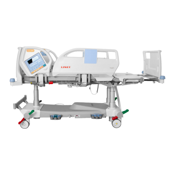
Page 10: Product Description
4 Product Description Fig. 2 Bed Overview (Eleganza 5) Removable Foot Board Split Siderail – Middle Section with Integrated Control Panels for Patient Split Siderail – Head Section Removable Head Board iBoard CPR Lever – Backrest Release Poles Adaptor Foot Switch Siderail Release Lever Four-part Mattress Platform with Ergoframe®... -
Page 11: Technical Specification
Accuracy of displayed weight values: ■ 0,5 kg (1,1 lbs) ■ Scales Class III 5.3 Mechanical Specifications (Eleganza 5) Parameter Value External Dimensions in Standard Bed Position (length x width) 219 cm x 100 cm Siderail Height above Mattress Platform... -
Page 12: Electrical Specifications (Eleganza 5)
5.6 Manufacturer’s Manual and Declaration - Electromagnetic Radiation Eleganza 5 is intended for the application in electromagnetic environment as specified below. The customer or user of the bed is responsible for the fact that these requirements are met. -
Page 13: Manufacturer's Manual And Declaration - Electromagnetic Resistance
5.7 Manufacturer’s Manual and Declaration - Electromagnetic Resistance Eleganza 5 is intended for the application in electromagnetic environment as specified below. The customer or user of the bed is responsible for the fact that these requirements are met. Resistance Test... - Page 14 Resistance Test Test Level as per IEC 60601 Level of Compli- Electromagnetic Environment ance Conducted high frequency 3 Vrms 3 Vrms ► It is recommended to use portable phenomena 150 kHz to 80 MHz and mobile HF communication equi- IEC 61000-4-6 pment around the bed in distances defined below.
-
Page 15: Use And Storage Conditions
Medical Bed The Eleganza 5 Medical Bed is intended for use in an electromagnetic environment in which radiated RF disturbances are cont- rolled. The customer or the user of the Eleganza 5 Medical Bed can help prevent electromagnetic interference by maintaining a minimum distance between portable and mobile RF communications equipment (transmitters) and the Eleganza 5 Medical Bed as recommended below, according to the maximum output power of the communications equipment. -
Page 16: Scope Of Delivery And Bed Variants
Notify the carrier and supplier of any deficiencies or damages immediately as well as in writing or make a note on the delivery note. 7.2 Scope of Delivery ■ Eleganza 5 hospital bed ■ User Manual 7.3 Eleganza 5 Variants... -
Page 17: Initial Instructions
8 Initial Instructions Set up the bed as follows: ► Unpack the bed. ► Check the delivery (see Scope of Delivery and Bed Variants). ► Remove isolating foil from the mains control box (see Battery Activation). ► Install equipment and accessories (see Installation). ►... -
Page 18: Installation
► Lock sleeve fitting. Fig. 4 Locking of the bed ends Mattress Platform Eleganza 5 without x-ray cassette holder has four removable parts of Mattress Platform (1,2,3 and 4). LEFT SIDE RIGHT SIDE Fig. 5 Parts of Mattress Platform D9U001GE0-0101_02... -
Page 19: Before Use
Potential Equalisation The bed is equipped with a standard protective connector. This connector is used for potential equalisation between the bed and any intravascular or intracardiac device connected to the patient to protect the patient from static electric hocks. Fig. 6b Potential equalisation - male Fig. -
Page 20: Mains Power Cable
Unsuitable surfaces: ■ Too soft, unsealed or defective flooring ■ Soft wooden flooring ■ Soft and porous stone floors ■ Carpeted floors with underlay ■ Soft linoleum ► For longer distances, ensure that the castor steering function (main control) is activated. ►... -
Page 21: Replacing The Battery
Signalisation The LED (on iBoard or Additional Supervisor Panel) indicates the battery’s charge status: Yellow LED Battery charge status Not lit Battery capacity is sufficient (charging completed) Short flashing (shortly lit, longer not lit) (circa 1.8 sec.) Battery is charging - continue charging until the LED is extingu- ished. -
Page 22: Removing The Bed From Use
Status “Discharged battery” The battery is regarded as discharged if the following condition is met: ► Defined decrease of voltage depending on discharging current ► This status is indicated by the battery status indicator flashing quickly. ► The electric CPR position is the only possible position. ►... -
Page 23: Manipulation
11 Manipulation WARNING! Risk of injury when adjusting the bed! ► Ensure that there are no body parts between the mattress platform elements and the mattress platform frame when adjusting the bed. ► Ensure that there are no body parts below the mattress platform frame before adjusting the bed. 11.1 Control Elements The bed is operated by different control elements. -
Page 24: Iboard
11.1.1 iBoard The iBoard is the main Control Element for the caregivers. It is integrated in the outside of both head sections of the siderails. ► Ensure that exclusively trained nursing staff operates the iBoard. Fig. 7a iBoard without Mattress Keyboard Display Keyboard - Scales Section Keyboard - Bed Exit/BedMonitor Section... - Page 25 Settings Section 1 2 3 4 1. MUTE Icon Fig. 8 Settings Section - Display and Keyboard 2. Service required Icon 3. Connection to server Icon MUTE (1) 4. State of charge (Battery) 5. Status Function MUTE can mute Siderail Alarm and Brake Alarm for 3 minutes. 6.
- Page 26 Status Indication Charging Lit segment 3, segment 2 and 1 is flashing alternately Faulty Battery or Battery Not Installed Empty frame 4 is flashing 3 2 1 Critically Discharged Battery Segment 3 is flashing, Bed Positioning Disabled SETTINGS During normal use icon 5 indicates time (hours : minutes). To enter Settings Mode: ►...
- Page 27 Positioning Section 18 17 16 Fig. 9 Positioning Section - Display and Keyboard 1. Autocontour Adjustment Buttons (simultaneous movement of the Backrest and Thighrest) 2. Mains Power LED 3. Battery LED 4. Lock Button and LED 4a. Locked Backrest LED 4b.
- Page 28 GO BUTTON The GO Button activates the keyboard of all Control Elements. Pressing GO Button will keep the keyboard active for 3 minutes. Pressing a button will keep the keyboard active for another 3 minutes. During this time the following is possible: ►...
- Page 29 MAINS POWER LED Status Meaning lit LED connected to the mains unlit LED disconnected from the mains flashing LED system error D9U001GE0-0101_02...
- Page 30 Scales Section Eleganza 5 is equipped with a weighing system that allows weighing the patient in bed. There are control buttons and display for the weighing system on the Scales section of iBoard. Scales Display and Keyboard Description Fig. 10 Scales Section - Display and Keyboard...
- Page 31 To tare weight: ► Ensure that nothing and nobody touches the bed except you. ► Press and hold button 1 (Zero/T) until value (icon 7) starts to flash. ► Release button 1. ► Press button 1 again to confirm taring. “0” is shown on the display. Place the patient on the bed.
- Page 32 To return to actual patient´s weight: ► Press button 2 while displaying saved value. After 10s actual patient´s weight appers instead of displayed memory record. NOTE The last record is saved as the first (M1) in sequence of 9 records. NOTE After pressing button 4 it is possible to hold the button additionally to save an actual patient´s weight.
- Page 33 Bed Exit Monitoring Section 13 12 Fig. 11 Bed Exit Monitoring Section - Display and Keyboard 1. ON Button 2. Bed Exit Monitoring Zone Button (Inner Zone) 3. Bed Exit Monitoring Zone Button (Outer Zone) 4. VOLUME Button (3 levels) 5.
- Page 34 To set Inner Zone: ► Press button 2. Icon 12 appears on the display. 4) ALARM Alarm is triggered when ■ patient has left selected monitored zone (Inner Zone or Outer Zone) ■ PAUSE interval elapsed and patient is not in ordered position To stop Alarm: ►...
- Page 35 Pop-ups Pop-up Meaning Required Action LOCK Function locked Unlock function X-RAY Incorrectly inserted X-Ray Cassette Insert X-Ray Cassette Holder Holder correctly GO Button not activated Activate GO Button SIDERAIL Siderail folded down (Lateral Tilt disa- Raise siderail up to enable Late- bled) ral Tilt Prevention from collision with floor during...
-
Page 36: Additional Supervisor Panel
11.1.2 Additional Supervisor Panel The Additional Supervisor Panel is a standard Control Element. The Additional Supervisor Panel can be hung on the foot end or on siderails if required. It is possible to hold the Additional Supervisor Panel in the hand while operating. 13 14 Fig. -
Page 37: Handset (Optional)
During this time the following is possible: ► Adjusting individual mattress platform elements by pressing the corresponding function buttons. ► Disabling individual functions with the lock buttons. Each time a function button is pressed, the keypad will remain active for another 3 minutes. Function Buttons The function buttons 4, 5, 7, 8, 10, 11, 12, 15, 16 and 17 are described in chapter Bed Positioning. -
Page 38: Integrated Control Panels For Patient
11.1.4 Integrated Control Panels for Patient The control panels integrated in the middle sections of the siderails allow the patient to adjust the positions of the Backrest, Thighrest and Autocontour. Optionally additional control panel is situated in the inner side of head section of siderails. 1. -
Page 39: Foot Control Bed Height (Optional)
11.1.5 Foot Control Bed Height (optional) The foot control is optional and allows setting the Height of the bed with one’s feet. 1. Protection Frame against Unwanted Activation 2. Raise Mattress Platform Pedal 3. Examination Position Pedal 4. Lower Mattress Platform Pedal Fig. -
Page 40: Bed Positioning
11.2 Bed Positioning Backrest To position Backrest use: ► iBoard ► Aditional Supervisor Panel ► Handset ► Integrated Control Panel for Patient (in middle siderail) ► Integrated Control Panel for Patient (in head siderail) Fig. 19 Backrest Angle on iBoard Display iBoard Display shows tendency of Backrest positioning with Backrest Angle. -
Page 41: Thighrest
Thighrest To position Thighrest use: ► iBoard ► Aditional Supervisor Panel ► Handset ► Integrated Control Panel for Patient (in middle siderail) ► Integrated Control Panel for Patient (in head siderail) iBoard: ► Press GO Button. ► Press selected part of Thighrest Adjustment Button (Fig. 21a) until intended position is reached. -
Page 42: Calfrest
Calfrest To position Calfrest position Thighrest firstly. To position Calfrest use: ► iBoard ► Aditional Supervisor Panel iBoard: ► Press GO Button. ► Press selected part of Calfrest Adjustment Button (Fig. 22a) until intended position is reached. Fig. 22a Calfrest Adjustment Button (iBoard) 1. - Page 43 iBoard: ► Press GO Button. ► Press selected part of Bed Height Adjustment Button (Fig. 23a) until intended position is reached. Fig. 23a Bed Height Adjustment Button (iBoard) Aditional Supervisor Panel: ► Press GO Button. ► Press selected part of Bed Height Adjustment Button (Fig. 23b) until intended position is reached.
-
Page 44: Autocontour
Autocontour To position Autocontour use: ► iBoard ► Handset ► Integrated Control Panel for Patient (in middle siderail) ► Integrated Control Panel for Patient (in head siderail) iBoard: ► Press GO Button. ► Press selected part of Autocontour Adjustment Button (Fig. -
Page 45: Emergency Trendelenburg Position
Emergency Trendelenburg Position To position Emergency Trendelenburg Position use: ► Aditional Supervisor Panel Fig. 26 Trendelenburg Position Aditional Supervisor Panel: ► Press GO Button. ► Press Trendelenburg Position Button (Fig. 27) until intended position is reached. Fig. 27 Trendelenburg Position Button (Aditional Supervisor Panel) Anti-Trendelenburg and Trendelenburg Tilt... -
Page 46: Bed Extension
Bed Extension To position Bed Extension use: ► iBoard ► Aditional Supervisor Panel iBoard: ► Press GO Button. ► Press selected part of Bed Extension Adjustment Button (Fig. 31a) until intended position is reached. Fig. 31a Bed Extension Adjustment Button (iBoard) 1. -
Page 47: Cardiac Chair Position
Cardiac Chair Position To position Cardiac Chair Position use: ► iBoard ► Aditional Supervisor Panel iBoard: ► Press GO Button. ► Press Cardiac Chair Position Button (Fig. 33a) until intended position is reached. Fig. 33a Cardiac Chair Position Button (iBoard) Aditional Supervisor Panel: ►... -
Page 48: Ergoframe
Lateral Tilt It is not possible to position Lateral Tilt with siderail folded down. To position Lateral Tilt use: ► Foot Control Tilt ► Aditional Supervisor Panel Fig. 35 Lateral Tilt Angle on iBoard Display iBoard Display shows Lateral Tilt tendency with Lateral Tilt Angle. -
Page 49: Siderails
11.3 Siderails The split siderails are components of the bed in contact with patient. A pneumatic spring supports the operation of the split siderails. The nursing personnel are responsible for the siderails being raised up while the patient is in bed. WARNING! Risk of injury, damaging or unintentional movement of the bed due to incorrect placement of accessories or Handset! -
Page 50: Cpr Backrest Release
11.4 CPR Backrest Release WARNING! Risk of injury due to lowering the backrest too quickly! ► Ensure that the siderails are in the low position. ► Ensure that there are no body parts between any movable parts of the bed. ►... -
Page 51: Castor Control
11.7 Castor Control CAUTION! Material damage due to incorrect transport and involuntary movement! ► Prior to transport, ensure that the bed is disconnected from the mains. ► Ensure that the castors are braked prior to assembly, disassembly and maintenance. ► Ensure that the castors are braked when the bed is occupied. -
Page 52: I-Drive Power (Optional)
11.8 i-Drive Power (optional) i-Drive Power System - Basic Description It is possible to equip the bed with the i-Drive Power wheel. The i-Drive Power helps hospital staff to drive the bed during patient transport with minimal manpower. The i-Drive wheel is located in the center of the bed under the undercarriage. i-Drive Power is equipped with its own battery and charger and it is not dependent on the bed functions so, if discharged you can still use the bed functions. - Page 53 Each bed can transport only single patient at a time and cannot be used to transport other items (except bed accessories in secured position). NOTE For information concerning uses other than those outlined in the “Specifications of Use” section above, please contact Linet ®. Manipulation CAUTION! Damage to i-Drive Power main control panel cable due to wrong cable placement! ►...
- Page 54 NOTE The i-Drive Power controller cannot control the bed functions. Control the bed using the bed control elements. NOTE The main control panel is enhanced with a touch sensor (1); your hand must always be in contact with the i-Drive Power control panel to use the functions. If released, the i-Drive Power will stop. NOTE Raising and lowering of the i-Drive wheel is electrically controlled by the i-Drive activation panel.
- Page 55 stop. The i-Drive motor is immediately stopped and the electric brake is activated after pressing the red STOP DRIVE Button (8) when braking or in emergency. i-Drive Power control system is automatically deactivated and the electric brake is activated if no i-Drive function is used for 3 minutes.
- Page 56 Fault Signalization The system is protected against failure states, by stopping and braking the drive system, and respective signalization. The fault indicator flashing briefly and the battery indicator shows the fault state. Some defects are cleared automatically (e.g.: drive overhe- ating).
-
Page 57: Mobi-Lift ® (Optional)
I-Drive Power Maintenance Periodical maintenance of the i-Drive Power must be done by qualified service technician or authorized service organization at least once a year. Service technician must check the following: ► battery status and eventual replacement of batteries (after maximum of three years of duty) ►... -
Page 58: X-Ray Lung Examination (Optional)
11.10 X-Ray Lung Examination (optional) The Backrest of the bed consists optionally of HPL and is x-ray translucent. The bed is equipped with an x-ray cassette holder inse- ted under the Backrest left side. This design allows taking x-ray images of the patient’s lungs without moving the patient manually. Necessary Steps before the Examination NOTE... -
Page 59: Mattress
Incompatibility with bed due to incorrect mattress dimensions! ► In the case of other mattresses check maximum approved mattress dimensions (chapter Technical Specification). The manufacturer recommends the use of the following mattress systems on the Eleganza 5 bed: PASSIVE MATTRESSES ACTIVE MATTRESSES ■... -
Page 60: Installation Of Scu (System Control Unit)
Material damage due to incorrect installation of SCU! ► If the SCU does not come factory-fitted, have it installed by a service engineer authorised by Linet ®. 12.3 Mattress Display and Keyboard Description The Mattress Display and Keyboard are situated in the middle section of the iBoard. -
Page 61: Accessories
Attach a plastic grab handle with an adjustable strap to the lifting pole. NOTE The date of manufacture is marked on the grab handle. Fig. 48 Lifting Pole Linet® recommends replacing the plastic grab handle every four years. Infusion Stand WARNING! Risk of injury due to use of incorrect accessories or because of incorrect use! Infusion Stands must only be used for their intended use. -
Page 62: Ventilation Circuit Holder
(placement on the Infusion Stand) Ventilation Circuit Holder The ventilation circuit holder prevents an extubation. ► Always use Linet ® ventilation circuit holder to prevent extubation during any procedures. Applying ventilation circuit holder: ► Put ventilation circuit holder in hole on right or left side of the Backrest frame. -
Page 63: Writing Shelf
Version B (with adapter) ► Put holder on sleeve fittings in multifunctional accessory adapter on chassis. ► Ensure the locking pin of oxygen bottle holder B is locked in sleeve fitting. Fig. 52 Oxygen Bottle Holder (in the adapter) Writing Shelf The Writing Shelf is intended for writing of nursing staff. -
Page 64: Accessories On Siderails
13.2 Accessories on Siderails Nurse Call Button for activating the Nurse Call function: The buttons for activating the Nurse Call function are located on the inner and outer sides of the head siderails. Speakers and microphones are located on the inner sides of the head siderails. Fig. -
Page 65: Protector
Make sure the fall risk assessment was done properly before Protector use. The Protector is an optional accessory for the Eleganza 5 bed. The main purpose of the Protector is to reduce the risk of fall espe- cially at very risky patients (confused restless patients). -
Page 66: Usb Connector
13.3 USB Connector USB Connector situated on the both sides of Backrest is intended for charging mobile phones and tablets. Fig. 57 USB Connector on the right side of Backrest WARNING! Risk of injury due to incorrect use! ► Ensure accessory pluged in USB connector is in pristine condition! User of the bed is responsible for the fact that this requirement is met. -
Page 67: Cleaning/Disinfection
■ by the EPA (Environmental Protection Agency) of the country in which the mattress replacement system is to be used. 14.1 Cleaning (Eleganza 5) Prepare for cleaning as follows: ►... -
Page 68: Daily Cleaning
14.1.1 Daily Cleaning Clean the following bed parts: ■ All control elements for adjusting the bed ■ All handles □ CPR release handle ■ Bed ends ■ Siderails (in highest position) ■ Freely accessible mattress surface ■ Mobi-Lift® ■ Accessory rails 14.1.2 Cleaning before Changing Patients Clean the following bed parts: ■... -
Page 69: Troubleshooting
15 Troubleshooting DANGER! Risk of mortal injury due to electric shock! ► If a fault occurs, have the electric motor, power box or other electrical parts repaired by qualified personnel exclusively. ► Do not open the protective covers of the electric motor or the power box. Error/Fault Cause Solution... -
Page 70: Maintenance
If the defect cannot be repaired, do not use the bed. NOTE Linet ® recommends attaching the maintenance plaque to the bed. To keep the bed functioning correctly, ensure that the following maintenance work is performed at the correct intervals. -
Page 71: Electric Control
16.3.5 Electric Control Plug connections ► Replace O-rings on connectors. ► Check plugs connections for dirt and defects. Clean or replace if necessary. ► Check that the plug connectors are properly seated. Motors ► Check motor movement (adjust bed positions). Check for incorrect and interrupted movements. -
Page 72: Maintenance Active Mattress
® Our responsible Linet ® Service partners will ensure your Linet ® products are up and running when you need them. For more information on available service support and contract offerings, please contact us at 877-815- 8895 and ask for technical support. -
Page 73: Disposal
17.1 Environment Protection Linet ® is aware of the importance of environmental protection for future generations. Within the whole LINET company is applied the environmental management system, which is in accordance with the internationally agreed standards ISO 14001. The interna- tional system recognition and certification ISO are based on the external audits executed by specialists from reputable international TŰV company. -
Page 74: Warranty
18 Warranty Linet ® will only be held responsible for the safety and reliability of products that are regularly serviced, maintained and used in accordance with the safety guidelines. Should a serious defect arise that cannot be repaired during maintenance: ►... -
Page 75: Standards And Regulations
19 Standards and Regulations Apllied norms are stated on Declaration of Conformity. The manufacturer adheres to a certified quality management system in compliance with the following standards: ■ EN ISO 9001 ■ EN ISO 14001 ■ EN ISO 13485 Manufacturer also meets quality system regulation in accordance with FDA regulation 21 CFR 820. D9U001GE0-0101_02... - Page 76 D9U001GE0-0101_02...
Need help?
Do you have a question about the ELEGANZA 5 and is the answer not in the manual?
Questions and answers