
Related Manuals for LINET Multicare LE


Summary of Contents for LINET Multicare LE
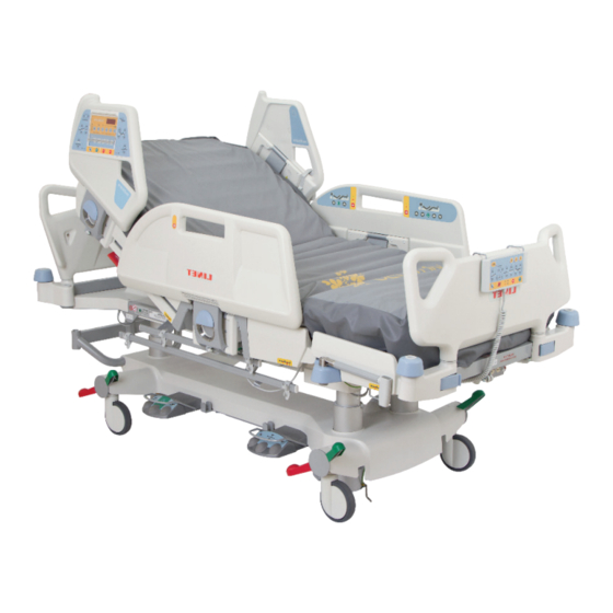
- Page 1 Instructions for Use and Technical Description Multicare LE Positionable bed for intensive care with scales and without scales D9U001MC5-0101 Version: 08 Publication Date: 2020-02...
- Page 2 Related links: www.linet.com D9U001MC5-0101 Version: 08 Publication date: 2020-02 Copyright © LINET, s.r.o., 2020 Translation © LINET, 2020 All rights reserved. All trademarks and brands are the property of the appropriate owners. The manufacturer reserves the right to changes in the contents of the instructions for use that relate to the product´s technical regulations.
-
Page 3: Table Of Contents
5.1 Identification of Applied Parts (Type B) ....... 20 13.6.7 i-Drive Power Activation/Deactivation ....52 5.2 Scales (only version with scales) ........ 20 13.6.8 Free Drive ..............52 5.3 Mechanical Specifications (Multicare LE) ....20 13.6.9 Accumulator ............52 5.4 Environment Conditions ..........21 13.6.10 Fault Signalization ..........53 5.5 Electrical Specifications (Multicare LE) ....... -
Page 4: Symbols And Definitions
21 Standards and Regulations ........69 1 Symbols and Definitions 1.1 Warning Notices 1.1.1 Types of Warning Notices Warning notices are differentiated by the type of danger using the following key words: ► CAUTION warns about the risk of material damage. ► WARNING warns about the risk of physical injury. ►... -
Page 5: Symbols On The Package
1.4 Symbols on the Package FRAGILE, HANDLE WITH CARE THIS WAY UP KEEP DRY (PROTECT FROM HUMIDITY) PAPER RECYCLING SYMBOL DO NOT USE HAND TRUCK HERE DO NOT STACK DURING STORAGE D9U001MC5-0101_08... -
Page 6: Symbols And Labels On The Bed
WARNING ONLY SUITABLE FOR INDOOR USE APPLIED PARTS TYPE B SAFETY ISOLATING TRANSFORMER, GENERAL CE MARK (MULTICARE LE WITH SCALES) CE MARK (MULTICARE LE WITHOUT SCALES) JACK FOR ATTACHMENT OF CONDUCTOR FOR POTENTIAL EQUALISATION SAFE WORKING LOAD WARNING AGAINST CRUSHING OR TRAPPING... - Page 7 DO NOT PUT ANY OBJECTS ON UNDERCARRIAGE MAXIMUM WEIGHT OF PATIENT WEIGHT OF BED DESIGNATION OF HOSPITAL BED FOR ADULTS ANTIBACTERIAL SURFACE FINISH WEEE SYMBOL (RECYCLE AS ELECTRONIC WASTE, DO NOT PUT INTO THE HOUSEHOLD WASTE) EAC MARKING (EURASIAN CONFORMITY) DO NOT POLLUTE THE ENVIRONMENT TÜV MARK GO BUTTON (PRESS TO ACTIVATE CONTROL ELEMENT)
- Page 8 RECYCLING SYMBOL MEDICAL DEVICE (COMPATIBLE WITH MEDICAL DEVICE REGULATION) D9U001MC5-0101_08...
-
Page 9: Serial Label With Udi
1.6 Serial Label with UDI Pictures of serial labels below serve just for explanation of the signs and fi elds on the serial labels. Fig. Serial Label with UDI (Multicare LE with scales) Fig. Serial Label with UDI (Multicare LE without scales) -
Page 10: Acoustic Signalisation
Scales Abbreviations maximum capacity of the weighing instrument minimum capacity of the weighing instrument verification scale interval tare value Fig. Serial Label (WS17) 1.7 Acoustic signalisation SOUND MEANING CONTINUOUS SOUND overheating accumulator overcurrent scales overload (only version with scales) actuator overload BEEP + CONTINUOUS SOUND Siderail Signal (lateral tilt + head siderail or foot siderail down) REPEATED BEEP: 0,6s sound / 2,6s silence... -
Page 11: Visual Signalisation
1.8 Visual signalisation 1.8.1 Mains Power LED (Multiboard, Attendant Control Panel) MAINS POWER LED MEANING connected to the mains flashing: 0,6s lit / 0,6s not lit keyboard error (flashing inverted to Lock LED) error (first fault) flashing: 0,1s lit / 0,1s not lit service mode not lit disconnected from the mains power transformer switching error 1.8.2 Accumulator Indicator (Multiboard, Attendant Control Panel) ACCUMULATOR INDICATOR... -
Page 12: Definitions
1.9 Definitions Basic Bed Configuration the pricelist model configuration, not including a mattress Bed Weight The value depends on the product configuration, accessories or customer adjustments. Clearance of Undercarriage the height from the floor to the lowest point of the undercarriage between the castors, for the manipulation of accessories under a braked bed in the standard position Duty Cycle... -
Page 13: Abbreviations
1.10 Abbreviations AC ( ~ ) Alternating Current European Conformity Cardiopulmonary Resuscitation Sound Intensity Unit Control Unit Configuration Number Direct Current DC ( Euroasian Conformity Electromagnetic Compatibility Field-effect transistor High Frequency High Pressure Laminate Intensive Care Unit INT. Duty Cycle Ingress Protection Intravenous Light Emitting Diodes... -
Page 14: Safety Instructions
2 Safety Instructions WARNING! Multicare LE bed should be left in its lowest position when the patient is unattended in order to reduce risk of injury due to falls! WARNING! Siderails of Multicare LE should be located in the „up“ position to reduce the risk of the patient accidentally... - Page 15 WARNING! If this equipment is modified, appropriate inspection and testing must be conducted to ensure continued safe use of the equipment. WARNING! An additional multiple socket-outlet or extension cord shall not be connected to the medical electrical system. WARNING! During specific investigations or treatments the significant risks of reciprocal interference posed by ME equip- ment may occur. WARNING! Staff expert assessment is needed to consider all individual cases of contraindications! WARNING! Certain bed positions are not suitable for specific diagnosis/medical conditions. Fowler position is not suitable ...
- Page 16 WARNING! Hospital personnel is allowed to use the weighing system (scales) for weighing patients only if they had been trained according to the instructions for use! WARNING! Risk of injury due to incorrect use! Do not use CLP mode for patients undergoing cervical traction. Before placing a patient on a Symbioso, always have a qualified person perform a risk assessment to ensure ...
- Page 17 ► Never cover the SCU while in use. ► Select a suitable location for the placement of bed accessories and other objects to prevent involuntary activation of buttons or controls which may result in the adjustment of bed positioning. ► Do not use the bed in the event parts have been removed (e.g.
-
Page 18: Intended Use
3 Intended use The intended use is the hospitalization of the patient in the intensive and acute care units, which includes above all the following aspects: ► Adjustment of the specific positions needed for the preventive reasons, routine nursing, treatments, mobilization, physiotherapy, examinations, sleeping, and relaxation. -
Page 19: Product Description
Foot control – lateral tilt Siderail release lever Foot control – bed height adjustment Castor control lever Mobi-Lift® handle Corner bumper Castor Attendant Control Panel NOTE For safe, easy handling, LINET® recommends that two technicians put the bed into service. D9U001MC5-0101_08... -
Page 20: Technical Specification
5 Technical Specification All technical data are rated data and are subject to construction and manufacturing tolerances. WARNING! If Multicare LE bed is used with Symbioso integrated mattress replacement system, respect values of mecha- nical and electrical specifications which can harm none of them! 5.1 Identification of Applied Parts (Type B) All part of the bed (and accessories) the patient can reach are type B Applied Parts. -
Page 21: Environment Conditions
5.4 Environment Conditions Use Conditions Ambient Temperature 10°C – 40°C Relative Humidity 30% – 75 % Atmospheric Pressure 795 hPa – 1060 hPa Storage and Transport Conditions Ambient Temperature -20°C – 50°C Relative Humidity 20% – 90 % Atmospheric Pressure 795 hPa –... -
Page 22: Electromagnetic Compatibility
5.6 Electromagnetic compatibility Bed is intended for hospitals except for near active HF surgical equipment and the RF shielded room of a medical system for mag- netic resonance imaging, where the intensity of EM disturbances is high. Bed has defined no essential performance. WARNING! It is recommended to avoid the use of this device next to or in block with other device, because it could lead to improper operation. -
Page 23: Manufacturer Instructions - Electromagnetic Susceptibility
5.6.2 Manufacturer instructions – electromagnetic susceptibility Immunity Tests Compliance level Electrostatic discharge (ESD) ± 8 kV for contact discharge IEC 61000-4-2 ± 15 kV for contact discharge Radiated RF 3 V/m IEC 61000-4-3 80 MHz – 2,7 GHz 80 % AM at 1 kHz Proximity fields from RF wireless communications equipment IEC 61000-4-3 See Table 1... -
Page 24: Use And Storage Conditions
Do not use bed lifts and hoists for lifting the bed (bed hoists for patients are permitted; clearance for the patient hoists is 15 cm). Multicare LE with Symbioso are designed for use in rooms for medical purposes. Electrical installations must therefore meet local norms laying down the necessary conditions for electrical installations. -
Page 25: Scope Of Delivery And Bed Variants
Notify the carrier and supplier of any deficiencies or damages immediately as well as in writing or make a note on the delivery note. 7.2 Scope of Delivery ■ Multicare LE medical bed ■ Mattress with cover - Applied part type B ■... -
Page 26: Putting Into Service
8 Putting into Service WARNING! Risk of injury when working on the bed! ► Ensure that the bed is disconnected from the mains connection prior to putting into service, putting out of service and maintenance. ► Ensure that the castors are locked prior to putting into service, putting out of service and maintenance. CAUTION! Material damage due to incorrect putting into service! ►... -
Page 27: Accumulator Activation
8.1 Accumulator Activation 8.1.1 Placement of Control Section Fig. Control section placement 8.1.2 Removing the Isolating Foil Fig. Isolating foil To remove isolating foil: ► Remove isolating foil from mains control box 1 by pulling strap 2. ► Check if isolating foil is complete and undamaged. ►... -
Page 28: Head Board And Foot Board
8.2 Head Board and Foot Board Dismount the foot board as follows: ► Unlock sleeve fittings. ► Pull foot board from sleeve fittings. ► Lock sleeve fittings. Install the foot board as follows: ► Unlock sleeve fittings. ► Slide foot board into sleeve fittings. ►... -
Page 29: Potential Equalisation
8.3 Potential Equalisation The bed is equipped with a standard protective connector. This connector is used for potential equalisation between the bed and any intravascular or intracardiac device connected to the patient to protect the patient from static electric shocks. Fig. -
Page 30: Before Use
8.4 Before Use Prepare the bed for service as follows: ► Connect the bed to the mains. ► Charge the accumulator. ► Raise and tilt the mattress platform to the highest position. ► Lower and tilt the mattress platform to the lowest position. ►... -
Page 31: Power Supply Cord (Mains Power Cable)
9 Power Supply Cord (Mains Power Cable) CAUTION! Disconnecting bed from the mains does not stop motions of the bed! ► Stop the bed before disconnection bed from the mains. Attachment plug is means of connecting and disconnecting bed from the mains. Power supply cable (mains power cable) must be attached with a hook at the head board during transport. -
Page 32: Replacing The Accumulator
The LED indicates the Accumulator charge status: Yellow LED Accumulator charge status Not lit Accumulator capacity is sufficient (charging completed) Short flashing (shortly lit, longer not lit) (circa 1.8 sec.) Accumulator is charging - continue charging until the LED is extinguished. -
Page 33: Removing The Bed From Use
To cancel this status: ► Press STOP button. Status “Discharged accumulator” The accumulator is regarded as discharged if the following condition is met: ■ Defined decrease of voltage depending on discharging current ■ This status is indicated by the accumulator status indicator flashing quickly. ■... -
Page 34: Manipulation
11 Manipulation WARNING! Risk of injury when adjusting the bed! ► Ensure that there are no body parts between the mattress support platform elements and the mattress support platform frame when adjusting the bed. ► Ensure that there are no body parts below the mattress support platform frame before adjusting the bed. 11.1 Siderails WARNING! Risk of injury, damaging or involuntary movement of the bed due to incorrect placement of accessories or... -
Page 35: Castor Control And Bed Transport
11.2 Castor Control and Bed Transport CAUTION! Material damage due to incorrect transport and involuntary movement! ► Prior to transport, ensure that the bed is disconnected from the mains. ► Prior to transport, ensure that the auxiliary outlet plug (if available) is disconnected from the mains. ►... -
Page 36: Cpr Backrest Release
11.3 CPR Backrest Release WARNING! Risk of injury due to lowering the backrest too quickly! ► Ensure that the siderails are in the lowest position. ► Ensure that there are no body parts between the siderails and the backrest. ► Press the backrest down using the mattress guard handle only. -
Page 37: Control Elements
The Multiboard is the main control element. It is integrated in the outside of both head siderails. ► Ensure that exclusively nursing staff trained for critical care operate the Multiboard. 11 10 Fig. Multiboard (Multicare LE) 1. Bed Height Adjustment Buttons 9. Calfrest Adjustment Buttons 2. Trendelenburg Tilt Button and Antitrendelenburg Tilt Button 10. - Page 38 Central STOP Button The central STOP button immediately interrupts all bed movements in case of unauthorized bed positioning or an electronic failure. Pressing the central STOP button for at least 0.3 seconds immediately stops all electronic bed movements. Activating GO Button The GO button activates the keypad or the touchscreens of all control elements.
- Page 39 Statuses (Multiboard) Pop-up Meaning Required Action LOCK Function locked. Unlock function if required! CASS Incorrectly inserted X-Ray Cassette Holder. Insert X-Ray Cassette Holder correctly! GO Button not activated. Press GO Button! SIDE Lateral Tilt disabled when siderail folded down. Raise siderail up to enable additional Lateral Tilting. Antitrendelenburg Tilt and Trendelenburg Tilt disa- Undo the Lateral Tilt to continue with Antitrendelen- COLL...
-
Page 40: Attendant Control Panel
11.5 Attendant Control Panel The Attendant Control Panel is a standard Control Element. The Attendant Control Panel can be hung on the foot board or on side- rails if required. It is possible to hold the Attendant Control Panel in the hand while operating. ►... - Page 41 Activating GO Button The button activates the keyboard of all control elements for 3 minutes. The function of the GO button is identical on all control elements. During this time the following is possible: ► Adjusting individual mattress support platform elements by pressing the corresponding function buttons. ►...
-
Page 42: Handset
11.5.1 Handset A handset is included with the bed as an optional feature. The position of the handset depends on the patient’s condition. The hand- set is available with and without button illumination. The illumination is activated for 7s if any button was pressed and the illuminati- on is activated for 3 minutes if GO Button was pressed. -
Page 43: Bed Height Foot Control
11.5.3 Bed Height Foot Control The foot control is optional and allows setting the height of the bed with one’s feet. Protection Frame against Unwanted Activation Foot Switch Raise Mattress Platform Foot Switch Examination Position Foot Switch Lower Mattress Platform Set the position as follows: ►... -
Page 44: Scales (Ws 17)
12 Scales (WS 17) 12.1 Scales Control Panel Multicare LE is equipped with a weighing system that allows weighing the patient in bed. The control panel for this system is part of the Multiboard. Fig. Control Panel Scales and Symbioso... -
Page 45: Taring
12.1.2 Taring The taring is done in the range from 5kg to 249,5kg. The taring is used to set “0” on the display before placing the patient on the bed. It is used to show actual weight of the patient. The taring must be done on the unloaded bed without patient. -
Page 46: Bed Exit Alarm
12.1.6 Bed Exit Alarm Any weight drop of more than 20 kg will activate the Bed Exit Alarm. To deactivate Bed Exit Alarm: ► Press Bed Exit Button 10 for 2 s. To activate Bed Exit Alarm: ► Press Bed Exit Button 10 for 2 s. To switch between Bed Exit Alarm zones: ►... -
Page 47: Equipment
13 Equipment 13.1 Accessory rails Load capacity: ► Maximum load of 5 kg (11.02 lbs) without leverage ► Maximum load of hook pair 10 kg (22.05 lbs) Accessories for hanging on the accessory rail: ► Urine bag holder ► Redon bottle basket ►... -
Page 48: Mobi-Lift
13.4 Mobi-Lift® Mobi-Lift® is optional. It serves as a support handle to enhance the patient’s safety when getting up. Mobi-Lift® is a support handle with a built-in height adjustment button. It allows the patient to raise and lower the mattress platform. Fig. -
Page 49: I-Drive Power (Optional)
13.6 i-Drive Power (optional) 13.6.1 i-Drive Power System - Basic Description It is possible to equip the bed with the i-Drive Power wheel. The i-Drive Power helps hospital staff to drive the bed during patient transport with minimal manpower. The i-Drive wheel is located in the center of the bed under the undercarriage. i-Drive Power is equipped with its own accumulator and charger and it is not dependent on the bed functions so, if discharged you can still use the bed functions. -
Page 50: Manipulation
Each bed can transport only one patient at a time and cannot be used to transport other items (except bed accessories in secured position). NOTE For information concerning uses other than those outlined in the “Specifications of Use” section above, please contact LINET ®. 13.6.4 Manipulation CAUTION! Damage to i-Drive Power main control panel cable due to wrong cable placement! ►... -
Page 51: Powered Drive
NOTE The i-Drive Power controller cannot control the bed functions. Control the bed using the bed control elements. NOTE The main control panel is enhanced with a touch sensor (1); your hand must always be in contact with the i-Drive Power control panel to use the functions. If released, the i-Drive Power will stop. NOTE Raising and lowering of the i-Drive wheel is electrically controlled by the i-Drive activation panel. -
Page 52: I-Drive Power Activation/Deactivation
13.6.7 i-Drive Power Activation/Deactivation Fig. i-Drive mains switch To activate the i-Drive Power: Check, if the mains switch of i-Drive Power is activated (1). Press the Activation button ON located on the activation panel. The i-Drive wheel will lower and the green indicator will flash. -
Page 53: Fault Signalization
13.6.10 Fault Signalization The system is protected against failure states, by stopping and braking the drive system, and respective signalization. The fault indicator flashing briefly and the accumulator indicator shows the fault state. Some defects are cleared automatically (e.g.: drive overheating). -
Page 54: I-Drive Power Maintenance
13.6.14 I-Drive Power Maintenance Periodical maintenance of the i-Drive Power must be done by qualified service technician or authorized service organization at least once a year. Service technician must check the following: ► accumulator status and eventual replacement of accumulator (after maximum of three years of duty) ►... -
Page 55: Mattress
CAUTION! Incompatibility with bed due to incorrect mattress dimensions! ► Check maximum approved mattress dimensions (chapter Technical Specification). The manufacturer recommends the use of the following mattress systems on the Multicare LE bed: PASSIVE MATTRESSES ACTIVE MATTRESSES ■ CliniCare 10 ■ ... -
Page 56: Active Mattress (Not Integrated)
Do not use any other System Control Units with Symbioso mattress! CAUTION! Material damage due to incorrect installation of SCU! ► If the SCU does not come factory-fitted, have it installed by a service engineer authorised by LINET ®. D9U001MC5-0101_08... -
Page 57: Mattress Control Panel
14.3.1 Mattress Control Panel Fig. Mattress Control Panel (Multiboard) CLP Mode Button (with indicator) MAX Mode Button (with indicator) Fowler Boost Button (with indicator) Service due Indicator System Error Indicator CPR indicator MUTE Button MCM mode Button D9U001MC5-0101_08... -
Page 58: Accessories
A plastic grab handle with an adjustable strap shall be attached to the lifting pole. NOTE The lifting pole adapter is optional. It is necessary to specify this feature in the order. NOTE The date of manufacture is marked on the grab handle. LINET® recommends replacing the plastic grab handle every four years. D9U001MC5-0101_08... -
Page 59: Infusion Stands
15.2 Infusion Stands WARNING! Risk of injury due to use of incorrect accessories or because of incorrect use! Infusion Stands must only be used for their intended use. Always read the instructions for use! ► Only mount an infusion pump to the lower (wider) telescopic section of an infusion stand above the head board/ foot board. -
Page 60: Ventilation Circuit Holder
15.4 Ventilation Circuit Holder The ventilation circuit holder prevents an extubation. ► Always use a LINET® ventilation circuit holder to prevent extubation when the bed is tilted laterally. Applying ventilation circuit holder: ► Put ventilation circuit holder in hole on right or left of head end. -
Page 61: Oxygen Bottle Holders
15.6 Oxygen Bottle Holders WARNING! Risk of injury with oxygen bottle holder due to incorrect use or due to careless driving! ► Ensure the oxygen bottle holder is correctly fi tted in correct position. ► It is necessary to place oxygen bottle holder (with or without O2 bottle) before transport to secure transport position. -
Page 62: Protector
► Always check that the siderails are properly locked. The Protector is an optional accessory for the Multicare LE bed. The main purpose of the Protector is to reduce the risk of patients falling off the bed. Fig. Multicare LE bed with Protector... -
Page 63: Cleaning/Disinfection
16 Cleaning/Disinfection Antibacterial surface finish: Selected parts of the Multicare LE bed are treated against the spread of bacteria with certified technology by Sanitized®. This tech- nology supplements regular bed disinfection procedures. Regular bed cleaning cannot be omitted relying only on the antibacterial surface finish. -
Page 64: Cleaning (Multicare Le)
► by the environmental protection agency of the country in which the mattress replacement system is to be used. LINET ® recommends the following cleaning agents: Parts to be cleaned Cleaning agents ■... -
Page 65: Cleaning Before Changing Patients
16.1.2 Cleaning before Changing Patients Clean the following bed parts: ► All control elements for adjusting the bed ► All handles □ CPR release handle ► Head Board and Foot Board ► Siderails (in highest position) ► Freely accessible mattress surface ►... -
Page 66: Troubleshooting
17 Troubleshooting DANGER! Danger to life due to electric shock! ► If a fault occurs ensure the electric motor, power box and other electrical parts checked by qualified personnel only. ► Do not open protective covers of the electric motor or power box. Error/Fault Cause Solution... -
Page 67: Maintenance
Ensure that maintenance is performed exclusively by manufacturer´s customer service or by authorised service personnel certified by the manufacturer. ► If the defect cannot be repaired, do not use the bed. LINET ® recommends attaching the maintenance plaque to the bed. 18.1 Regular maintenance ► Check regularly movable parts for wear. -
Page 68: Disposal
Based on the Directive No. 2002/96/ EC (Directive WEEE - Waste, Electric and Electronic Equipments) the company LINET, s. r. o. is registered in the List of Electric and Electronic Equipment Producers (Seznam výrobců elektrozařízení) on the Ministry of the Environment of the Czech Republic... -
Page 69: Warranty
20 Warranty LINET ® will only be held responsible for the safety and reliability of products that are regularly serviced, maintained and used in accordance with the safety guidelines. Should a serious defect arise that cannot be repaired during maintenance: ►...
Need help?
Do you have a question about the Multicare LE and is the answer not in the manual?
Questions and answers