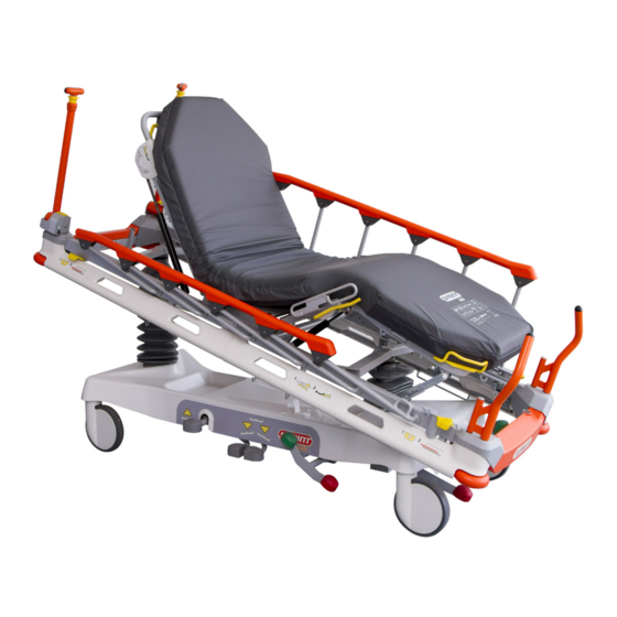
LINET Sprint 100 User Manual And Technical Description
Universal transport stretcher
Hide thumbs
Also See for Sprint 100:
- Service manual (38 pages) ,
- Instructions for use and technical description (73 pages)

Related Manuals for LINET Sprint 100


Summary of Contents for LINET Sprint 100
- Page 1 User Manual and Technical Description Sprint 100 Universal Transport Stretcher D9U001ES1-0110 Version: 02 Publication Date: 2018-09...
- Page 2 Related links: www.linet.com D9U001ES1-0110 Version: 02 Publication Date: 2018-09 Copyright © LINET, s.r.o., 2018 Translation © LINET, 2018 All rights reserved. All trademarks and brands are the property of the appropriate owners. The manufacturer reserves the right to changes in the contents of this manual that relate to the product´s technical regulations.
-
Page 3: Table Of Contents
5.1 Identification of Applied Parts (Type B) ....... 15 15.3.2 Completeness ............56 5.2 Mechanical Specifications ..........15 15.3.3 Wear ...............56 5.3 Environment Conditions (Sprint 100) ......16 15.3.4 Functioning ............56 6 Use and Storage Conditions ........16 15.4 Safety Checks ............57 7 Scope of Delivery and Bed Variants ......17 15.5 Linet... -
Page 4: Symbols And Definitions
1 Symbols and Definitions 1.1 Warning Notices 1.1.1 Types of Warning Notices Warning notices are differentiated by the type of danger using the following key words: ► CAUTION warns about the risk of material damage. ► WARNING warns about the risk of physical injury. ►... -
Page 5: Symbols On The Bed
1.4 Symbols on the Bed READ INSTRUCTIONS FOR USE SAFE WORKING LOAD WARNING AGAINST CRUSHING OR TRAPPING JACK FOR ATTACHMENT OF CONDUCTOR FOR POTENTIAL EQUALISATION POSSIBLE RISK APPLIED PARTS TYPE B ONLY SUITABLE FOR INDOOR USE MAXIMUM WEIGHT OF PATIENT WEIGHT OF BED MET MARK RECYCLING SYMBOLS... - Page 6 PLACE MONITOR ON THIS SIDE OF THE MONITOR SHELF DO NOT PLACE MONITOR ON THIS SIDE OF THE MONITOR SHELF INSTRUCTION FOR PLACEMENT OF THE MONITOR SHELF (L=LEFT, R=RIGHT) FOLD THE MARKED FOLDABLE INFUSION STAND AS THE FIRST ONE FOLD THE MARKED FOLDABLE INFUSION STAND AS THE SECOND ONE MANUFACTURER MANUFACTURING DATE REFERENCE NUMBER...
-
Page 7: Symbols On The Mattress
1.5 Symbols on the Mattress READ INSTRUCTIONS FOR USE CE MARKING COVER MATERIALS ARE FIRE RESISTANT TO BS7175, SOURCE 0, 1 AND 5 DO NOT IRON DO NOT USE PHENOL DO NOT WRING REGULARLY INSPECT THE INSIDE OF THE COVER FOR CONTAMINATION NO MACHINE WASH DISINFECT USING SOLUTION CONTAINING LESS THAN 1000 ppm OF CHLORINE (REFER TO INSTRUCTIONS FOR USE) - Page 8 MATTRESS FOOT PART D9U001ES1-0110_02...
-
Page 9: Serial Label With Udi
/ GTIN (Global Trade (GS1 Data Matrix) Item Number) DI + PI = UDI Symbols Serial Number PI (Product Identifier) Fig. Serial Label with UDI (Sprint 100) Fig. Mattress Label Fig. Mattress Label Fig. Mattress Label (Sprint Standard) (Sprint Comfort) (Sprint Advanced) -
Page 10: Definitions
1.7 Definitions Basic Bed Configuration the pricelist model configuration, not including a mattress Bed Weight The value depends on the product configuration, accessories or customer adjustments. Clearance of Undercarriage the height from the floor to the lowest point of the undercarriage between the castors, for the manipulation of accessories under a braked bed in the standard position Reference number Reference number depends on configuration. -
Page 11: Safety Instructions
2 Safety Instructions ► Follow the instructions carefully. ► Use the bed exclusively if it is in perfect working order. ► If necessary, check the bed functions daily or at each shift change. ► Ensure any user has read and understood this manual completely before operating the product. ►... -
Page 12: Intended Use
Sprint 100 is a universal mechanical transport bed intended for urgent care and acute admission. Its purpose is to support patient´s body during his transport in critical condition. At the same time Sprint 100 is intended for basic examination of the transported patient. -
Page 13: Product Description
4 Product Description SPRINT 100 WITH 4-PART MATTRESS SUPPORT PLATFORM 11 10 Fig. Bed Overview (Sprint 100 with 4-part Mattress Support Platform) Mattress Support Platform Collapsible Siderail Thighrest Handle Bushings for Accessories Corner Bumper Brake Pedal Siderail Release Mechanism Thighrest Control... - Page 14 SPRINT 100 WITH 2-PART MATTRESS SUPPORT PLATFORM Fig. Bed Overview (Sprint 100 with 2-part Mattress Support Platform) Mattress Support Platform Collapsible Siderail Bushings for Accessories Corner Bumper Brake Pedal Siderail Release Mechanism Drive Pedal and Brake Pedal (optional) Foot End Lowering Pedal...
-
Page 15: Technical Specification
Siderails ■ Bed Ends ■ Mattress 5.2 Mechanical Specifications SPRINT 100 WITH 4-PART MATTRESS SUPPORT PLATFORM Parameter Value External Dimensions in Standard Bed Position (length x width) 211 cm x 76 cm Siderail Height above Mattress Support Platform 4 cm (minimum), 36,5 cm (maximum) -
Page 16: Environment Conditions (Sprint 100)
SPRINT 100 WITH 2-PART MATTRESS SUPPORT PLATFORM Parameter Value External Dimensions in Standard Bed Position (length x width) 211 cm x 76 cm Siderail Height above Mattress Support Platform 4 cm (minimum), 36,5 cm (maximum) Siderail Length 125 cm Distance between siderail bars... -
Page 17: Scope Of Delivery And Bed Variants
Notify the carrier and supplier of any deficiencies or damages immediately as well as in writing or make a note on the delivery note. 7.2 Scope of Delivery ■ Sprint 100 Universal Transport Stretcher ■ User Manual 7.3 Sprint 100 Variants Basic Configuration:... -
Page 18: Putting Into Service
► Do not use pedals for lifting or lowering if the bed is not in horizontal position! NOTE For safe, easy handling, Linet ® recommends having two technicians assemble the bed. Set up the bed as follows: ► Unpack the bed. -
Page 19: Mattress Support Platform
8.1 Mattress Support Platform Sprint 100 has Mattress Support Platform with two sections or four sections. 2-PART MATTRESS SUPPORT PLATFORM LEFT SIDE RIGHT SIDE Fig. 2-part Mattress Support Platform 4-PART MATTRESS SUPPORT PLATFORM LEFT SIDE RIGHT SIDE Fig. 4-part Mattress Support Platform... -
Page 20: Potential Interconnection (Optional)
8.2 Potential Interconnection (optional) The bed is equipped with a standard protective connector. This connector is used for potential equalisation between the bed and any intravascular or intracardiac device connected to the patient to protect the patient from static electric shocks. Fig. - Page 21 Suitable surfaces: ■ Tile ■ Hard linoleum ■ Poured flooring Unsuitable surfaces: ■ Too soft, unsealed or defective flooring ■ Soft wooden flooring ■ Soft and porous stone floors ■ Carpeted floors with underlay ■ Soft linoleum ► For longer distances, ensure that the castor steering function (main control) is activated. ►...
-
Page 22: Manipulation
9 Manipulation WARNING! Risk of injury when adjusting the bed! ► Ensure that there are no body parts between the Mattress Support Platform elements and the Mattress Support Platform frame when adjusting the bed. ► Ensure that there are no body parts below the Mattress Support Platform frame before adjusting the bed. Control Signs Meaning Backrest Control... -
Page 23: Collapsible Siderails
9.1 Collapsible Siderails The collapsible siderails are components of the bed in contact with patient. The nursing personnel are responsible for the siderails being raised up while the patient is in bed. WARNING! Risk of injury due to incorrectly latched siderail! ►... -
Page 24: Castor Control
Fig. Manipulation with Siderail Release Mechanism at foot end Fig. Manipulation with Siderail Release Mechanism at head 9.2 Castor Control CAUTION! Material damage due to incorrect transport and involuntary movement! ► Ensure that the castors are braked prior to assembly, disassembly and maintenance. ►... -
Page 25: Braked Bed
9.2.1 Braked Bed To brake the bed: ► Press red Brake pedal (1 or 2) to the lower position. All four castors are braked. Fig. Positions of Brake pedals 1. Brake Pedal (standard) - RED 2. Brake Pedal (optional) - RED 9.2.2 Forward Movement (Steering) To set forward movement: Press green Drive pedal (3 or 4) to the lower position. -
Page 26: Unrestricted Movement
9.2.3 Unrestricted Movement To set unrestricted movement: ► Leave all Brake pedals and Drive pedals in their middle position. All four castors are unlocked. Unrestricted movement is enabled. D9U001ES1-0110_02... -
Page 27: Bed Positioning
9.3 Bed Positioning 9.3.1 Backrest To position Backrest: ► press Backrest Release Handles towards the Backrest frame ► position Backrest Fig. Manipulation with Backrest Release Handle Fig. Positions of Backrest Release Handles D9U001ES1-0110_02... -
Page 28: Thighrest (Only For 4-Part Mattress Support Platform)
9.3.2 Thighrest (only for 4-part Mattress Support Platform) To lift Thighrest: ► press Thighrest control and repeat it until intended position is reached If the Thighrest is loaded use Thighrest handle to lift the Thighrest. To lower Thighrest: ► press and hold Thighrest control and push Thighrest down until intended position is reached Fig. -
Page 29: Calfrest (Only For 4-Part Mattress Support Platform)
9.3.3 Calfrest (only for 4-part Mattress Support Platform) To position Calfrest, position Thighrest firstly. To lift Calfrest: ► lift Calfrest by the handle to intended position ► lower the Calfrest so that catch fits in the ratchet-bar To lower Calfrest: ► lift Calfrest slightly by the handle ►... -
Page 30: Lifting
9.3.4 Lifting To lift Mattress Support Platform: ► press Lifting pedal and repeat it until intended position is reached To perform bleeding procedure of hydraulic units: ► press Lifting pedal 10 times in the highest bed position Fig. Positions of Lifting pedals D9U001ES1-0110_02... -
Page 31: Lowering
9.3.5 Lowering CAUTION! Risk of material damage due to objects on the undercarriage cover! ► Do not place objects on the undercarriage cover outside storage space! ► Respect dimensions of objects placed in storage space of the undercarriage cover! ► For information about objects intended for storage in the space of undercarriage cover follow chapter Accessories. -
Page 32: Trendelenburg Position
9.3.6 Trendelenburg Position WARNING! Risk of injury due to improper use of Trendelenburg Position! ► Hospital staff is responsible for assessing if the physical and psychological state of the patient is in accordance with use of the Trendelenburg Position. ► Hospital staff is responsible for assessing whether used bedclothes increase the risk of patient´s sliding from the bed! To reach Trendelenburg position:... -
Page 33: Anti-Trendelenburg Tilt
9.3.7 Anti-Trendelenburg Tilt WARNING! Risk of injury due to patient´s sliding! ► Hospital staff is responsible for assessing whether used bedclothes increase the risk of patient´s sliding from the bed! To reach Anti-Trendelenburg Tilt: ► press Foot End Lowering pedal until intended position is reached Fig. -
Page 34: Cardiac Chair Position
9.3.8 Cardiac Chair Position To reach Cardiac Chair Position: ► lift the Mattress Support Platform to facilitate Thighrest and Backrest positioning (1) ► lift the Thighrest (2) ► lift the Backrest (3) ► lift the Mattress Support Platform to the maximum position (4) ►... -
Page 35: Cpr Backrest Release
9.4 CPR Backrest Release In order to adjust Mattress Support Platform for Cardiopulmonary Resuscitation (CPR) it is necessary to position Backrest to the lowest position and Mattress Support Platform to the lowest position. In the case of Mattress Support Platform with 4 sections posi- tion Backrest and Thighrest to the lowest position and Mattress Support Platform to the lowest position. -
Page 36: Equipment
10 Equipment 10.1 Accessory Holders (optional) Accessory holders are intended for hanging accessories. Fig. Accessory holders (on side) 10.2 Undercarriage Cover CAUTION! Risk of material damage due to objects on the undercarriage cover! ► Do not place objects on the undercarriage cover outside storage space! ►... -
Page 37: Sprung Retractable Fifth Castor (Optional)
10.3 Sprung Retractable Fifth Castor (optional) During middle position of pedals Sprung Retractable Fifth Castor is around 12 mm above floor. When bed is braked Sprung Retractable Fifth castor is around 65 mm above floor. To activate the Fifth castor: ►... -
Page 38: Examination With C-Arm (In-Bed Fluoroscopy)
The in-bed C-arm examination is suitable above all for the unstable patients contraindicated to be moved. Sprint 100 beds intended for use with C-arm have different structure of the Backrest in order to avoid artifacts on the x-ray images. - Page 39 88 cm 44 cm 39 cm 32 cm Fig. Space for the lower part of a C-arm Necessary steps before the examination with C-arm: ► Make sure that Mattress Support Platform is in the highest position. ► Position upper part of C-arm above the patient. The x-ray tube of the C-arm is located between the undercarriage and the Mattress Support Platform.
-
Page 40: Mattress
& egress or with agitated patients. The bottom surface of the Sprint 100 mattress has an ‘anti-slip’ coating. This is intended to help prevent the mattress moving around on the Sprint 100 mattress support platform during patient transport, mattress support platform articulation or whilst the patient is moving around. -
Page 41: Mattresses Specifications
Fig. Passive Mattress (Sprint 100 with 4-part mattress support platform) 11.3 Mattresses Specifications Mattress for 2-part Mattress Support Platform Specification Sprint Standard Sprint Comfort Sprint Advanced Length 193 cm 193 cm 193 cm Width 66 cm 66 cm 66 cm Height... -
Page 42: Cleaning Of Passive Mattress
11.4 Cleaning of Passive Mattress CAUTION! Incorrect cleaning/disinfection can damage the mattress! ► Do not use pressure or steam cleaners. ► Follow the instructions and observe the dosages recommended by the manufacturer. ► Ensure that disinfectants are selected and applied by qualified hygiene experts only. ►... -
Page 43: Routine Cleaning And Disinfection
11.4.2 Routine Cleaning and Disinfection Cleaning the mattress: ► Check mattress cover top for any signs of damage or for liquid ingress. ► Replace or repair and completely disinfect mattress cover top if damaged. Also check if the mattress core is not contaminated. -
Page 44: Accessories
12 Accessories WARNING! Risk of injury due to incompatible accessories! ► Use exclusively original accessories from the manufacturer. The manufacturer is not responsible for the use of unapproved accessories. Accessory head end foot end on sides Accessory Rail with plastic ... -
Page 45: Din Rail
12.2 DIN Rail DIN Rail is intended for hanging accessories. It is located on the sides of bed or at head end / foot end. Fig. DIN Rail (on side) Fig. DIN Rail (at head end or foot end) D9U001ES1-0110_02... -
Page 46: Foldable Infusion Stands
12.3 Foldable Infusion Stands Foldable infusion stand equipped with 2 hooks is intended for carrying IV bags or baskets for intravenous solutions. The pair of foldable infusion stands can serve as handles for bed transport also when they are raised. It is possible to extend height of the foldable infusion stand and to fold down the foldable infusion stand again. -
Page 47: Infusion Stand
To extend foldable infusion stand: ► Extend the foldable infusion stand by taking its telescopic part out. To facilitate procedure put control ring (3) up during extending. To shorten foldable infusion stand: ► Put control ring (3) up during inserting the telescopic part into the foldable infusion stand. -
Page 48: Monitor Shelf
12.5 Monitor Shelf Monitor shelf is intended for carrying a monitor when the monitor shelf is folded inwards the bed (4). When the monitor shelf is folded outwards the bed (3) it serves for writing. When the monitor shelf is folded down (2) it serves as a foot board. Monitor shelf is equipped with straps to fix a monitor on the monitor shelf. -
Page 49: Handles
12.6 Handles Pair of handles is intended for bed transport. The handles are located in head end corners or foot end corners. There are 3 types of the handles: removable, foldable or fixed in their positions. Fig. Simple handles (at head end or foot end) Fig. -
Page 50: Paper Sheet Holder
12.8 Paper Sheet Holder Paper Sheet Holder is intended for holding a paper sheet. Paper Sheet Holder is located at foot end. On the opposite bed end, the paper sheet can be fixed under the mattress. Fig. Positions for Paper Sheet Holder Fig. -
Page 51: Oxygen Bottle Holder
12.10 Oxygen Bottle Holder WARNING! Risk of injury with Oxygen Bottle Holder due to incorrect use or due to careless driving! ► Ensure the Oxygen Bottle Holder is correctly fitted in correct position. ► It is necessary to place Oxygen Bottle Holder (with or without O2 bottle) before transport to secure transport position. - Page 52 To adjust position of the Oxygen Bottle Holder: ► Move Oxygen Bottle Holder to intended position. Fig. Oxygen Bottle Holder (at head end on the left) - posi- Fig. Oxygen Bottle Holder (at head end on the left) - position 2 tion 1 D9U001ES1-0110_02...
-
Page 53: Cleaning/Disinfection
■ by the EPA (Environmental Protection Agency) of the country in which the mattress replacement system is to be used. 13.1 Cleaning (Sprint 100) Prepare for cleaning as follows: ►... -
Page 54: Daily Cleaning
13.1.1 Daily Cleaning Clean the following bed parts: ■ All control elements for adjusting the bed ■ All handles ■ Bed ends ■ Siderails (in highest position) ■ Freely accessible mattress surface ■ Accessory rails 13.1.2 Cleaning before Changing Patients Clean the following bed parts: ■... -
Page 55: Troubleshooting
14 Troubleshooting Error/Fault Cause Solution Faulty Mattress Support Platform Height Obstacle on the undercarriage cover Remove the obstacle. Adjustment Obstacle under the pedals Remove the obstacle. Faulty pedal. Notify the manufacturer´s service department. Lowering Backrest from the upright position Obstacle under the Backrest or in the drive Remove the obstacle not possible mechanism. -
Page 56: Maintenance
If the defect cannot be repaired, do not use the bed. NOTE Linet ® recommends attaching the maintenance plaque to the bed. To keep the bed functioning correctly, ensure that the following maintenance work is performed at the correct intervals. -
Page 57: Safety Checks
® Our responsible Linet ® Service partners will ensure your Linet ® products are up and running when you need them. For more information on available service support and contract offerings, please contact us at podpora.servis@linet.cz and ask for techni- cal support. -
Page 58: Disposal
16.1 Environment Protection Linet ® is aware of the importance of environmental protection for future generations. Within the whole LINET company is applied the environmental management system, which is in accordance with the internationally agreed standards ISO 14001. The interna- tional system recognition and certification ISO are based on the external audits executed by specialists from reputable international TŰV company. -
Page 59: Warranty
17 Warranty Linet ® will only be held responsible for the safety and reliability of products that are regularly serviced, maintained and used in accordance with the safety guidelines. Should a serious defect arise that cannot be repaired during maintenance: ►... -
Page 60: Standards And Regulations
18 Standards and Regulations 18.1 Sprint 100 Apllied norms: ■ IEC 60601-1 ■ IEC 60601-1-6 ■ ISO 14971 ■ ANSI/AAMI ES60601-1 ■ CAN/CSA C22.2 NO. 60601-1 18.2 Manufacturer The manufacturer adheres to a certified quality management system in compliance with the following standards: ■ ISO 9001 ■ ISO 14001 ■ ISO 13485 ■ MDSAP (Medical Device Single Audit Program) D9U001ES1-0110_02...
Need help?
Do you have a question about the Sprint 100 and is the answer not in the manual?
Questions and answers