
Related Manuals for LINET Image 3 B


Summary of Contents for LINET Image 3 B
- Page 1 User manual and technical description Image 3 B Bariatric hospital bed for acute care D9U001AM2-0101 Version: 04 Publication date: 2018-08...
- Page 2 Manufacturer: LINET spol. s r. o. Želevčice 5 274 01 Slaný Czech Republic Tel.: +420 312 576 111 Fax: +420 312 522 668 E-mail: info@linet.cz http://www.linet.cz Image 3 B Bariatric hospital bed for acute care Author: LINET, s.r.o. Related links: www.linet.cz...
-
Page 3: Table Of Contents
7.3 Isolating Foil ............................16 8 Assembly ........................17 8.1 Potential Equalisation........................17 8.2 Mattress platform ..........................18 8.3 Image 3 B (1AM2) - Single Collapsible Side Rails and Powder Coated Bed Ends ......19 8.4 Bed Ends ............................20 9 Operation ........................22 9.1 Initial Operation ..........................22 9.2 Battery ...............................22... - Page 4 Disposal ............................46 16 Warranty ......................... 47 17 EC Declaration of Conformity ..................48 18 Technical Specifications ....................49 18.1 Mechanical Specifications ......................49 18.2 Environment Conditions ......................49 18.3 Electrical Specification .........................50 18.4 PB 4X Electronic System of Image 3 B ..................51 D9U001AM2-0101_04...
-
Page 5: Symbols
1 Symbols Warning Notices 1.1.1 Types of Warning Notices Warning notices are differentiated by the type of danger using the following key words: Caution - risk of material damage. Warning - risk of physical injury. Danger - risk of fatal injury. 1.1.2 Structure of Warning Notices SIGNAL WORDS! -
Page 6: Symbols And Labels On The Product
Symbols and Labels on the Product Read user manual. Attention Thermal protection of transformer Only suitable for indoor use Protection against accidents due to electrical current – Type B instruments Safety isolation transformer, general CE mark of conformity with EU regulation Jack for attachment of conductor for potential equalisation Safe Working Load... -
Page 7: Serial Label With Udi
WEEE symbol (recycle as electronic waste, do not put into the household waste) Serial label with UDI Fig. Serial Label with UDI (Image 3 B) Address of Distributor Manufacturing Date (Year-Month-Day) DI (Device Identifier) / GTIN (Global Trade Item Number) -
Page 8: Safety And Dangers
2 Safety and Dangers WARNING! Image 3 B bed should be left in its lowest position when the patient is unattended in order to reduce risk of injury due to falls! WARNING! Siderails of Image 3 B should be located in the „up“ position to reduce the risk of the patient... -
Page 9: Safety Instructions
WARNING! Do not modify this equipment without authorization of the manufacturer. WARNING! If this equipment is modified, appropriate inspection and testing must be conducted to ensure continued safe use of the equipment. WARNING! An additional MULTIPLE SOCKET-OUTLET or extension cord shall not be connected to the MEDICAL ELECTRICAL SYSTEM. - Page 10 Position the mains cable so that there are no loops or bends in the cable; protect the cable from mechanical wear and tear. Improper handling of mains cable can cause an electric shock hazard, other serious injuries or damage to the bed.
-
Page 11: Conditions Of Use
Conditions of Use The bed may not be used and stored in indoor environments: Where there is a risk of explosion. Containing inflammable anaesthetics. The bed is designed for use in rooms for medical purposes. Electrical installations must therefore meet local stan- dards laying down the necessary conditions for electrical installations. -
Page 12: Functioning
Always conduct the risk assessments required for the selection of suitable equipment. Image 3 B is a standard care hospital bed. It is designed for supporting the bariatric patient in several positions such as horizontal, Trendelenburg, Cardiac Chair etc. -
Page 13: Scope Of Delivery And Bed Variants
CAUTION! Damage to the bed due to incorrect use! Use 125 mm castors exclusively on flat, even surfaces without any gaps. Features – Image 3 B Model 1AM2 (model no. see product label): Mattress Platform mattress platform consisting of removable plastic segments ... -
Page 14: Applied Parts Type B
Applied parts type B All the accesories the patient can reach are type B applied parts. List of type B applied parts: ACP Nurse control panel (supervisor control panel) Handset Satellite controller Side rails Bed ends ... -
Page 15: Setup
6 Setup Transport For safe transport, observe the following: Ensure no cables are run over when moving a bed. Ensure the mains cable is attached with a hook (at the head end of the bed). Ensure the castors are unlocked before moving the bed during the loading/unloading process (see Castor Control and Bed Transport). -
Page 16: Battery Activation
7 Battery Activation Placement of Control Section Removing the Isolating Foil Pull Isolating Foil Check if isolating foil is complete and undamaged as shown: If isolating foil is damaged, contact the manufacturer’s service department immediately. NOTE: It is recommended to wear gloves when removing the isolating foil. D9U001AM2-0101_04... -
Page 17: Assembly
8 Assembly WARNING! Risk of injury when working on the bed! Ensure the bed is disconnected from the mains connection prior to assembly, disassembly and maintenance. Ensure the castors are locked prior to assembly, disassembly and maintenance. CAUTION! Material damage due to incorrect assembly! ... -
Page 18: Mattress Platform
Mattress platform The mattress platform consists of removable plastic sections. To remove/install sections of the mattress platform: Pull out mattress platform sections. Install mattress platform section. The correct fitting of section is signalized by hearable “click”. Ensure that mattress platform sections are fitted correctly by trying pull the section up with little manpower. -
Page 19: Image 3 B (1Am2) - Single Collapsible Side Rails And Powder Coated Bed Ends
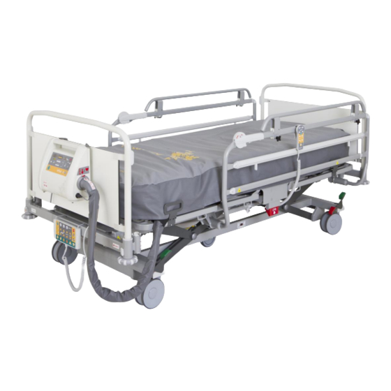
Image 3 B (1AM2) - Single Collapsible Side Rails and Powder Coated Bed Ends Fig. 4 Overview Image 3 B – Single Collapsible Side Rails 1. Foot end of the bed 2. Virtuoso II compressor 3. Side rail release mechanism 4. -
Page 20: Bed Ends
Bed Ends NOTE: The bed ends may be delivered in several decor colour variants. WARNING! Risk of injury when inserting the bed ends! To insert bed ends into corner posts, hold them by the corner handles on top with both hands. ... - Page 21 8.4.2 Powder coated bed ends Fig. 7 Unlocked bed end Fig. 6 Locked bed end 1. Unlocked (the bed end can be removed) 2. Locked (bed end is locked) 8.4.3 Installation of bed ends Install the bed ends as follows: ...
-
Page 22: Operation
9 Operation Initial Operation CAUTION! Material damage due to temperature difference! If there is a considerable temperature difference between the bed and the place of operation (after transport/storage), leave bed unconnected for 24 hours to allo the temperature to equalise. Prepare the bed for service as follows: ... -
Page 23: Battery Charging
Use only batteries approved by the manufacturer. The manufacturer provides a 6-month warranty for the full function of batteries. Check the battery functionality at least once a month in accordance with the user and service manuals and have the batteriy changed if necessary. ... -
Page 24: Status Faulty Battery
Status Faulty Battery The battery is regarded as faulty if at least one of the following conditions applies: Battery charging constantly Low voltage on battery Low charging current of battery Status “faulty battery” is indicated: By the battery status indicator being constantly lit. ... -
Page 25: Manipulation
10 Manipulation WARNING! Risk of injury when adjusting the bed! Ensure there are no body parts between the mattress platform elements and the mattress platform frame when adjusting the bed. Ensure there are no body parts below the mattress platform frame before adjusting the bed. ... -
Page 26: Supervisor Control Panel (Nurse Controller)
10.1 Supervisor control panel (nurse controller) Supervisor panel is main control panel of the bed. Nurse controller can be placed in the shelf. We recommend placing ACP panel on the bed end of the bed or hold it in the hands while controlling the bed. Fig. - Page 27 To set positions: Activate the keypad by pressing the GO button. Press and hold corresponding button until required position is reached. 10.1.1 Central STOP Button The central STOP button 7 immediately interrupts all bed movements. Pressing central STOP button 7 for at least 0.3 seconds immediately stops all electronic bed movements. 10.1.2 Activating GO Button The GO button 18 activates the keypads on all control elements except the foot control.
- Page 28 10.1.5 Position Buttons WARNING! Risk of injury due to moving parts! Ensure no body parts are trapped between moving parts of the bed and mattress platform. Ensure no persons or body parts are close to the bed or accessories (e.g. infusion stand, lifting pole) when the mattress platform is moving.
-
Page 29: Handset
NOTE: Depending on the patient’s condition, the nursing staff decides whether the patient is allowed to adjust the bed’s position. If required, prevent the patient from adjusting the bed as follows: Disable functions. Unplug handset. ® NOTE: The handset can be plugged into another LINET hospital bed with the Plug and Play slot. D9U001AM2-0101_04... -
Page 30: Night Bed Lightning
10.3 Night Bed Lightning It is possible to equip Image 3 B with undercarriage lightning. The lightning helps the patient or hospital personnel to better orientate in room with lowered or turned off light. The lowered intensity of lightning is set up after turning the bed on. -
Page 31: Cpr Backrest Release
10.5 CPR backrest release WARNING! Risk of injury due to lowering the backrest too quickly! Ensure single collapsible side rails are in their lowest position. Ensure split plastic side rails are in their highest position. Ensure there are no body parts between side rails and backrest. ... -
Page 32: Side Rails
10.6 Side rails The single collapsible side rails are components of the bed. The side rails cannot be dismounted. Hospital personnel are responsible for locking side rails in the highest position when the patient is on the bed. To fold the siderail down: ... -
Page 33: Castor Control And Bed Transport
10.7.3 Brake Alarm – Signalization of Unbraked Bed It is possible to equip Image 3 B with signalization of unbraked bed. The signalization of unbraked bed signalizes, that bed is connected to the mains but is not braked. This status is signalized by acoustic signal. To shut down acoustic signal brake the bed or unplug bed from the mains. -
Page 34: Accessories
NOTE: The manufacturer assumes no responsibility for the use of accessories not approved by the manufacturer. NOTE: All accessories conform to IEC 60601-2-52:2010. The following accessories are suitable for the Image 3 B: Lifting pole powder-coated chrome-plated ... - Page 35 Insert the lifting pole into both housings (Fig. 14) at the corners at the head of the bed with the help of a second person Ensure that both safety pins are locked into place NOTE: The date of manufacture is marked on the grab handle. LINET® recommends replacing the plastic grab handle every four years. D9U001AM2-0101_04...
- Page 36 11.1.2 Infusion Stand WARNING! Risk of injury due to incompatible accessories! Use infusion stands exclusively for accessories listed in the instructions for use. Do not use infusion stands for hanging infusion pumps, dosing devices etc. as this equipment might collide with movable parts of the bed.
- Page 37 Fig. 17 Installing the Extender® on the side rail Fig. 16 Inserting the screw Fig. 19 Securing the Extender® Fig. 18 Image 3 B with installed Extender® Install the Extender® as follows: Place the Extender® on the upper edge of the side rail (Fig. 17). Side rails must be in the upper position.
- Page 38 ® 11.1.5 Image 3 B Protector WARNING! Risk of injury due to patient falling out of bed! Ensure the Protector is securely anchored to the housing. ® To check stability, push the Protector up without touching the release button.
-
Page 39: Cleaning And Disinfection
12 Cleaning and Disinfection WARNING! Risk of injury when working on the bed! Prior to assembly, disassembly, cleaning and maintenance, ensure that all adjustment functions are locked. Ensure the bed is disconnected from the mains during cleaning process. ... -
Page 40: General Instructions For Cleaning And Disinfection
12.2 General Instructions for Cleaning and Disinfection 12.2.1 Daily Cleaning It is recommended to clean all parts of the bed which are touched by patient or personnel (e.g. side rails, bed ends, handset, lifting pole etc.) and all handles, all control elements and accessory rails. 12.2.2 Cleaning before Changing Patients It is recommended to completely clean and disinfects all parts of the bed which are touched by patient or personnel (see Daily Cleaning), mattress platform, columns, undercarriage covers and mattress. -
Page 41: Choosing Of Detergents Or Disinfections
Risk of damaging the bed due to use of incorrect detergent! Always consult choosing of the detergent and its dilution with manufacturer of the detergents according to the material table below. Changing Part of bed – Image 3 B Material (*) Daily C&D Complete C&D patient C&D Side rails (stickers) ... -
Page 42: Troubleshooting
13 Troubleshooting DANGER! Danger to life due to electric shock! If a fault occurs ensure the electric motor, power box and other electrical parts checked by qualified personnel only. Do not open protective covers of the electric motor or power box. Error/Fault Cause Solution... -
Page 43: Maintenance
14.1 Maintenance Work ® The connector replacement should only be carried out by service personnel trained by LINET . For service related instructions, please refer to the service documentation. Ensure the following maintenance work is performed every 12 months by the manufacturer or by a qualified service organisation trained and certified by the manufacturer. -
Page 44: Functioning
14.1.3 Wear Check all bolts and tighten if necessary. Check all locking mechanisms. Check the bed for wear, scratches or rub marks. Eliminate the cause if necessary. Have any defective parts replaced. 14.2 Functioning Check that all bed adjustments reach the maximum position. - Page 45 NOTE: The manufacturer will give a certificate to service organisations in which the manufacturer declares that ® ® the service organisation is qualified to perform maintenance on LINET products. On request, the LINET will ® provide service documentation and circuit diagrams for qualified service technicians trained by LINET D9U001AM2-0101_04...
-
Page 46: Disposal
PCB or CFC. Noise emissions and vibrations meet the directives for ® healthcare facilities. LINET has taken care to ensure all wood used in the production of its bed systems is responsibly source (Mahagony, Jacaranda, Ebony, Teak or wood from Amazonian / rainforests are not used. -
Page 47: Warranty
16 Warranty LINET® will only be held responsible for the safety and reliability of products that are regularly serviced and used in accordance with the safety guidelines. Should a serious defect arise that cannot be repaired during maintenance: Do not continue to use the bed. -
Page 48: Ec Declaration Of Conformity
17 EC Declaration of Conformity D9U001AM2-0101_04... -
Page 49: Technical Specifications
18 Technical Specifications 18.1 Mechanical Specifications Dimensions 220 cm x 110 cm Siderail Height Above Mattress Support Platform 48 cm Side Rails Length 146 cm Maximum Mattress Height 26 cm Mattress Support Platform Dimensions (Mattress) 200 cm x 100 cm Mattress Support Platform Extension 0 cm / 10 cm / 22 cm / 30,5 cm 28 cm –... -
Page 50: Electrical Specification
2x T1.6A L 250 V for 230 V version / 2x T3.15A L 250 V for 100-127 V version NOTE Upon request, LINET® can deliver hospital beds with electrical specifications that comply with regional standards (custom voltage, different mains plugs). -
Page 51: Pb 4X Electronic System Of Image 3 B
EMC information given in this Manual. Image 3 B is intended for the application in electromagnetic environment as specified below. The customer or user of the bed is responsible for these requirements are met. Manufacturer’s Manual and Declaration - Electromagnetic... - Page 52 Manufacturer’s Manual and Declaration - Electromagnetic Resistance 18.4.1 Resistance Test Test Level as per Level of Compliance Electromagnetic IEC 60601 Environment ± 6 kV for contact ± 6 kV for contact Electrostatic Ensure that the ± 8 kV for air ±...
- Page 53 Resistance Test Test Level as per Level of Electromagnetic Environment IEC 60601 Compliance Conducted high 3 Vrms 3 Vrms Do not use portable and mobile HF frequency 150 kHz to 80 MHz communication equipment near the phenomena bed. IEC 61000-4-6 Observe the distances indicated below.
- Page 54 RF communications equipment and the Image 3 B Medical Bed The Image 3 B Medical Bed is intended for use in an electromagnetic environment in which radiated RF disturbances are controlled. The customer or the user of the Image 3 B Medical Bed can help prevent...
Need help?
Do you have a question about the Image 3 B and is the answer not in the manual?
Questions and answers