Table of Contents
Advertisement
Quick Links
Advertisement
Table of Contents

Related Manuals for Smartgen HGM6100LT Series


Summary of Contents for Smartgen HGM6100LT Series
- Page 1 HGM6100LT SERIES (HGM6110LT/6120LT) GENSET CONTROLLER USER MANUAL...
- Page 2 SmartGen Technology at the address above. Any reference to trademarked product names used within this publication is owned by their respective companies. SmartGen Technology reserves the right to change the contents of this document without prior notice. Table 1 – Software Version Date...
-
Page 3: Table Of Contents
13.1 CUMMINS ISB/ISBE ........................41 13.2 CUMMINS QSL9 ..........................41 13.3 CUMMINS QSM11 (IMPORT) ......................42 13.4 CUMMINS QSX15-CM570 ......................42 13.5 CUMMINS GCS-MODBUS ....................... 43 13.6 CUMMINS QSM11 ........................... 43 HGM6100LT Series Genset Controller User Manual Page 3 of 50... - Page 4 13.15 SCANIA ............................47 13.16 VOLVO EDC3 ..........................47 13.17 VOLVO EDC4 ..........................48 13.18 VOLVO-EMS2 ..........................48 13.19 YUCHAI ............................49 13.20 WEICHAI ............................49 FAULT FINDING ............................ 50 HGM6100LT Series Genset Controller User Manual Page 4 of 50...
-
Page 5: Overview
OVERVIEW HGM6100LT series automatic controller is specially designed for applying to extremely high/low temperature (-40ºC~+70ºC) environment. It is an automatic control and monitoring system for genset, which integrates digital, intelligent and network techniques. It can reliably work in extreme temperature environment due to its heated LCD and special electronic components. - Page 6 Multiple conditions of crank disconnect (speed sensor, oil pressure, generator frequency) can be selected; With emergency start function; With flywheel teeth numbers automatic identification function; Widely power supply range: (8~35)VDC, accommodating to different starting battery voltage environment; HGM6100LT Series Genset Controller User Manual Page 6 of 50...
-
Page 7: Specification
20s after power-on; after 2 minutes after power-on, the dynamic display response speed is normal. Overall Dimensions 209mm x 166mm x 45mm Panel Cutout 186mm x 141mm C.T. Secondary Current 5A (rated) Working Temperature (-40~70)°C HGM6100LT Series Genset Controller User Manual Page 7 of 50... - Page 8 IP65: when water-proof gasket installed between control panel and Protection Level enclosure. Apply AC2.2kV voltage between high voltage terminal and low voltage Insulation Strength terminal. The leakage current is not more than 3mA within 1min. Weight 0.65kg HGM6100LT Series Genset Controller User Manual Page 8 of 50...
-
Page 9: Operation
Up cursor and increase value in setting menu. Scroll screen; Down/Decrease Down cursor and decrease value in setting menu. Return to homepage when in main interface; Home/Return Exit when in parameters setting interface. HGM6100LT Series Genset Controller User Manual Page 9 of 50... -
Page 10: Controller Panel
J1939 gensets, press start key in auto mode or stop mode, ECU power outputs and status indicator always illuminates. Auto Mode Indicator: only illuminate in auto mode; blink in auto mode and start delay count down. HGM6100LT Series Genset Controller User Manual Page 10 of 50... -
Page 11: Automatic Start/Stop Operation
When entering “Genset at Rest”, genset will automatically judge if it has stopped; When genset stops, it will enter into standby mode; if genset failed to stop, controller will issue alarm (“Fail to Stop” alarm will be displayed in LCD). HGM6100LT Series Genset Controller User Manual Page 11 of 50... -
Page 12: Manual Start/Stop Operation
When operators observed the genset has started successfully, loose the keys and the controller enters safety delay with start stops to output. HGM6100LT Series Genset Controller User Manual Page 12 of 50... -
Page 13: Protection
When the oil pressure of genset is less than threshold and Enabled Low Oil Pressure Stop Inhibited or Input Low Oil Pressure Stop Inhibited is Low Oil Pressure active, controller will send warning alarm signal and it will be displayed in LCD. HGM6100LT Series Genset Controller User Manual Page 13 of 50... - Page 14 User Configured the controller meets the selection of active range (not inactive), the Warn controller will initiate shutdown alarm signal, and the LCD will display the “User Configured 5” warning. HGM6100LT Series Genset Controller User Manual Page 14 of 50...
-
Page 15: Shutdown Alarm
When sensor hasn’t connected to corresponding port, controller will OP Sensor Open send shutdown alarm signal and it will be displayed in LCD. Maintenance Due Maintenance type is running time. When genset running time is longer HGM6100LT Series Genset Controller User Manual Page 15 of 50... - Page 16 When controller detects that the input port 4 selects 33 “User User Configured Configured”, close/open is active and the action selects “Shutdown Shutdown Alarm”, when the controller meets the selection of active range (not HGM6100LT Series Genset Controller User Manual Page 16 of 50...
- Page 17 LCD will display the “User Configured 1 Shutdown”. NOTE: ECU warning and shutdown alarm explains that check engine according to displayed alarm contents; otherwise check engine user manual according to SPN alarm code for gaining information. HGM6100LT Series Genset Controller User Manual Page 17 of 50...
-
Page 18: Connections
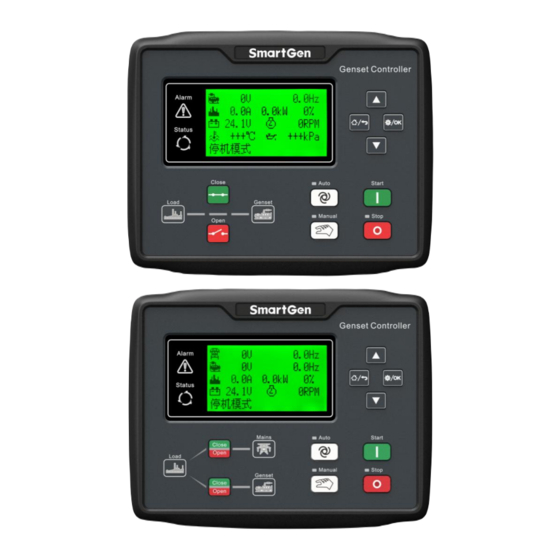
CONNECTIONS Compared with HGM6120LT, HGM6110LT doesn’t have 3-phase input terminal of mains voltage. The back panel of HGM6120LT is as below. Fig.3 – Controller Back Panel Drawing HGM6100LT Series Genset Controller User Manual Page 18 of 50... - Page 19 Generator V phase Voltage 1.0mm Connect to V phase output (2A fuse is recommended). sensing Input Generator W phase Voltage 1.0mm Connect to W phase output (2A fuse is recommended). Sensing Input HGM6100LT Series Genset Controller User Manual Page 19 of 50...
- Page 20 NOTE 1: USB port in controller rear panel is configurable parameter port; user can directly program via PC. NOTE 2: ETHERNET port in controller rear panel is network monitoring port; user can directly program via PC. HGM6100LT Series Genset Controller User Manual Page 20 of 50...
-
Page 21: Parameter Range And Definition
If “ETS output time” set as 0, it is the time 18(13) Fail to Stop Delay (0-120)s from end of idle delay to genset at rest; if not HGM6100LT Series Genset Controller User Manual Page 21 of 50... - Page 22 (only suited for oil pressure sensor, except for low oil pressure alarm signal inputted by programmable input port.) 30(25) Fuel Level (0-100)% When fuel level sensor value under this point HGM6100LT Series Genset Controller User Manual Page 22 of 50...
- Page 23 8. Factory default: High temperature shutdown. 45(40) Aux. Input 1 Set (0-23) See table 9. 46(41) Aux. Input 1 Active (0-1) Factory default: close. 47(42) Aux. Input 1 Delay (0-20.0)s HGM6100LT Series Genset Controller User Manual Page 23 of 50...
- Page 24 Temp. Sensor Curve 70(65) (0-14) SGD. See table 10. Type Pressure Sensor 71(66) (0-14) SGD. See table 10. Curve Type Fuel Level Sensor 72(67) (0-7) SGD. See table 10. Curve Type HGM6100LT Series Genset Controller User Manual Page 24 of 50...
- Page 25 0: Default Theme; 1: OEM Plant Theme; 88(83) Custom Theme (0-2) 2: Terminal User Theme 89(84) Fuel Output Time (1-60)s It is the time of the genset fuel output during HGM6100LT Series Genset Controller User Manual Page 25 of 50...
- Page 26 Default Gateway 192.168.0.2 (98) DNS Address 211.138.24.66 (99) Cooling (0-255) Unit:℃ (100) Temp. Cooling (0-255) Unit:℃ (101) Temp. Charger Voltage (0-1) 0: Controller HGM6100LT Series Genset Controller User Manual Page 26 of 50...
- Page 27 2: Shutdown Alarm 0: Inactive Input Port 3 Action (0-2) 1: Warn (118) Type 2: Shutdown Alarm 0: Inactive Input Port 4 Action (0-2) 1: Warn (119) Type 2: Shutdown Alarm HGM6100LT Series Genset Controller User Manual Page 27 of 50...
- Page 28 NOTE7: In teeth configuration interface, if being in teeth configuration status and frequency is larger than 20Hz, press start key for auto calculating teeth numbers and press confirm key for changing teeth numbers. HGM6100LT Series Genset Controller User Manual Page 28 of 50...
-
Page 29: Defined Contents Of Auxiliary Outputs 1-4
Used for ECU engine and control its power. ECU Warn Indicate ECU sends a warning signal. ECU Shutdown Indicate ECU sends a shutdown signal. ECU Comm. Failure Indicate controller not communicates with ECU. HGM6100LT Series Genset Controller User Manual Page 29 of 50... -
Page 30: Defined Contents Of Auxiliary Inputs 1-5
Inhibit Start Auto process won’t be executed. When input is disabled, genset will automatically start or stop judging by mains normal or not. Remote Control All keys in panel is inactive except HGM6100LT Series Genset Controller User Manual Page 30 of 50... - Page 31 The action type, range and delay time can be selected in this state. When the input port is active, the controller will execute User Configured the related actions of the input port according to the selected action range. HGM6100LT Series Genset Controller User Manual Page 31 of 50...
-
Page 32: Sensor Selection
4 User Configured (4-20)mA sensor. 5 User Configured (0-5)V 6 Digital Closed 7 Digital Open NOTE: It needs special instructions for ordering when the genset uses (4-20)mA or (0-5)V sensor. HGM6100LT Series Genset Controller User Manual Page 32 of 50... -
Page 33: Conditions Of Crank Disconnect Selection
6) If generator frequency has not been selected, controller will not measure and display the relative parameters (can be applied to the pump set); if speed has not been selected, the speed will be calculated by the generating signal. HGM6100LT Series Genset Controller User Manual Page 33 of 50... -
Page 34: Parameter Setting
User may select display language as Chinese, English, Spanish, Russian, Portuguese, Turkish, Polish and French. LCD contrast Press ) can adjust LCD contrast to make LCD characters clearer. Adjustment range is 0-7. HGM6100LT Series Genset Controller User Manual Page 34 of 50... -
Page 35: Sensor Setting
Table 12 – Conventional Pressure Unit Conversion Table (pa) kgf/cm - - - 1.02x10 1x10 1.45x10 1kgf/cm 9.8x10 0.98 14.2 1bar 1x10 1.02 14.5 - - 1psi 6.89x10 7.03x10 6.89x10 HGM6100LT Series Genset Controller User Manual Page 35 of 50... -
Page 36: Commissioning
ATS and make genset take load. If it not likes this, please check connections of ATS according to this manual. — If there are any other questions, please contact SmartGen’s service. HGM6100LT Series Genset Controller User Manual... -
Page 37: Typical Application
TYPICAL APPLICATION Fig.5 – HGM6110LT Typical Application Diagram Fig.6 – HGM6120LT Typical Application Diagram HGM6100LT Series Genset Controller User Manual Page 37 of 50... - Page 38 Fig.7 – Single Phase 2 Wire Connection Diagram Fig.8 – 2 Phase 3 Wire Connection Diagram NOTE: Recommend that the output of crank and fuel expand high capacity relay. HGM6100LT Series Genset Controller User Manual Page 38 of 50...
-
Page 39: Installation
OVERALL DIMENSION AND PANEL CUTOUT Fig.9 – Case and Overall Dimensions HGM6100LT series controller can be applicable to (8~35) VDC battery voltage. Battery negative must be reliably connected to engine shell. The connection between controller power (B+ and B-) and battery (B+ and B-) should not be less than 2.5mm... - Page 40 When there is load current, open circuit is inhibited in the CT secondary side. 5) Withstand Voltage Test When the controller has been installed in the control panel, during the test please disconnect all the terminals, in case high voltage damages the controller. HGM6100LT Series Genset Controller User Manual Page 40 of 50...
-
Page 41: Connections Of Controller With J1939 Engine
CAN_SCR SAE J1939 shield-E (connect to ECU terminal only). CAN(H) SAE J1939 signal-C Using impedance 120Ω connecting line. CAN(L) SAE J1939 return-D Using impedance 120Ω connecting line. Engine type: Cummins-CM850. HGM6100LT Series Genset Controller User Manual Page 41 of 50... -
Page 42: Cummins Qsm11 (Import)
SAE J1939 shield-E (connect to ECU terminal only). CAN(H) SAE J1939 signal-C Using impedance 120Ω connecting line. CAN(L) SAE J1939 return-D Using impedance 120Ω connecting line. Engine type: Cummins QSX15-CM570. HGM6100LT Series Genset Controller User Manual Page 42 of 50... -
Page 43: Cummins Gcs-Modbus
Output”. Starting relay output Connect with starter coil directly. CAN_SCR CAN communication shielding line. CAN(H) Using impedance 120Ω connecting line. CAN(L) Using impedance 120Ω connecting line. Engine type: common J1939. HGM6100LT Series Genset Controller User Manual Page 43 of 50... -
Page 44: Cummins Qsz13
Starting relay output Connect to starter coil directly. CAN_SCR CAN communication shielding line. CAN(H) CAN(H) Using impedance 120Ω connecting line. CAN(L) CAN(L) Using impedance 120Ω connecting line. Engine type: common J1939. HGM6100LT Series Genset Controller User Manual Page 44 of 50... -
Page 45: Deutz Emr2
Programmable output 1 Output”. Starting relay output communication shielding line CAN_SCR (connect to one terminal only). CAN(H) Using impedance 120Ω connecting line. CAN(L) Using impedance 120Ω connecting line. Engine type: MTU-MDEC. HGM6100LT Series Genset Controller User Manual Page 45 of 50... -
Page 46: Mtu Adec (Smart Module)
SAM (X23 port) Remark CAN_SCR X23 3 CAN communication shielding line. CAN(H) X23 2 Using impedance 120Ω connecting line. CAN(L) X23 1 Using impedance 120Ω connecting line. Engine type: Common J1939. HGM6100LT Series Genset Controller User Manual Page 46 of 50... -
Page 47: Perkins
Terminals of controller “Stand alone” connector Remark Set programmable output 1 as “Fuel Programmable output 1 Output”. Starting relay output ECU power; Programmable output 2 Set programmable output 2 as "ECU power". HGM6100LT Series Genset Controller User Manual Page 47 of 50... -
Page 48: Volvo Edc4
Using impedance 120Ω connecting line. CAN(L) 2(Lo) Using impedance 120Ω connecting line. Engine type: Volvo-EMS2. NOTE: When this engine type is selected, preheating time should be set to at least 3 seconds. HGM6100LT Series Genset Controller User Manual Page 48 of 50... -
Page 49: Yuchai
CAN(L) 1.34 Using impedance 120Ω connecting line. Engine type: GTSC1. NOTE: If there is any question of connection between controller and ECU communication, please feel free to contact SmartGen service. HGM6100LT Series Genset Controller User Manual Page 49 of 50... -
Page 50: Fault Finding
Check engine type settings; Check connections between controller and engine. EHERNET Interface Cannot Connect Check cloud server’s domain name and port number; Cloud Platform Check controller’s IP and DNS address. _________________________________ HGM6100LT Series Genset Controller User Manual Page 50 of 50...
Need help?
Do you have a question about the HGM6100LT Series and is the answer not in the manual?
Questions and answers