
Related Manuals for Smartgen HGM6100U2C Series


Summary of Contents for Smartgen HGM6100U2C Series
- Page 1 HGM6100U2C SERIES (HGM6110U2C/6120U2C) GENSET CONTROLLER USER MANUAL SMARTGEN (ZHENGZHOU) TECHNOLOGY CO., LTD.
- Page 2 Smartgen Technology at the address above. Any reference to trademarked product names used within this publication is owned by their respective companies. SmartGen Technology reserves the right to change the contents of this document without prior notice. Software Version Date...
- Page 3 HGM6100U2C SERIES GENSET CONTROLLER 1 SUMMARY HGM6100U2C series automatic controller, integrating digital, intelligent and network techniques, is used for automatic control and monitoring system of genset. It can carry out functions of automatic start/stop, data measurement, alarm protection and three “remote” (remote control, remote measure and remote communication).
- Page 4 HGM6100U2C SERIES GENSET CONTROLLER 2 PERFORMANCE AND CHARACTERISTICS HGM6100U2C controller has two types: HGM6110U2C: Used for single unit automation. It controls generator to start/stop by remote start signal; HGM6120U2C: Based on HGM6110U2C, it adds mains AC monitoring and mains/generator automatic switching control (AMF), especially suitable for the automation system composed by mains and genset.
- Page 5 HGM6100U2C SERIES GENSET CONTROLLER Hours counter (HC) can accumulate Max. 999999 hours. Start times can accumulate Max.999999 times. Control protection: Automatic start/stop of genset, load transfer(ATS control) and perfect failure display and protection; With ETS, idle speed control, pre-heat control, speed droop/raising control, all of them are relay output;...
- Page 6 HGM6100U2C SERIES GENSET CONTROLLER 3 SPECIFICATION Items Contents Working Voltage DC8.0V to DC35.0V, continuous power supply <3W(Standby mode: ≤2W) Power Consumption AC System 3P4W AC15V - AC360 V (ph-N) 3P3W AC30V - AC620 V (ph-ph) 1P2W AC15V - AC360 V (ph-N)
- Page 7 HGM6100U2C SERIES GENSET CONTROLLER 4 OPERATION 4.1 KEYS DSCRIPTION Icon Keys Description Can stop generator under Manual/Auto mode; Can reset shutdown alarm; Press this key at least 3 seconds to test panel indicators are OK Stop/ Reset or not(lamp test);...
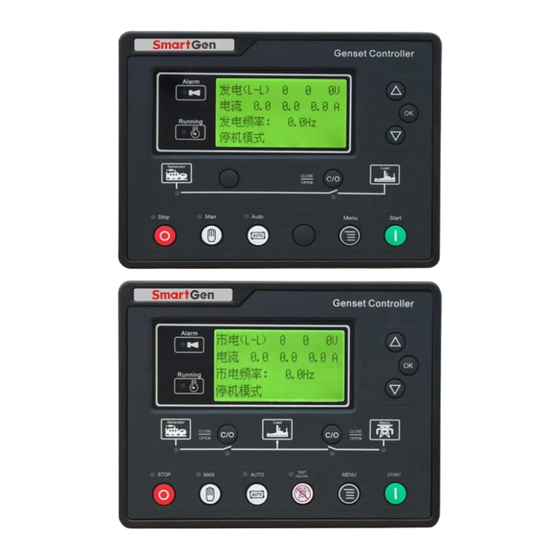
- Page 8 HGM6100U2C SERIES GENSET CONTROLLER 4.2 CONTROLLER PANEL HGM6110U2C Panel Indicators HGM6120U2C Panel Indicators HGM6100U2C Genset Controller 2016-12-19 Version 1.0 Page 9 of 34...
- Page 9 HGM6100U2C SERIES GENSET CONTROLLER 4.3 AUTOMATIC START/STOP OPERATION Auto mode is activated by pressing the , LED indicator beside the button is illuminating which confirms this action. Starting Sequence, HGM6120U2C: When mains is abnormal (over/under voltage, lack of phase), enter into “Mains Abnormal Delay”...
- Page 10 HGM6100U2C SERIES GENSET CONTROLLER When entering “ETS Delay”, ETS relay is energized to output, fuel relay output is disconnected. When entering “Genset at Rest”, genset will automatically judge if it has stopped. When genset has stopped, enter into standby mode; if genset failed to stop, controller will alarm (“Fail to Stop”...
- Page 11 HGM6100U2C SERIES GENSET CONTROLLER 4.4 MANUAL START/STOP OPERATION HGM6120U2C, Auto Mode is active when press and its indicator illuminates. Press , then controller enters into “Manual Test Mode” and its indicator is illuminating. Under both of the modes, press to start genset, it can automatically detect crank disconnect and accelerate to high speed running.
- Page 12 HGM6100U2C SERIES GENSET CONTROLLER 5 PROTECTION 5.1 WARNINGS When controller detects the warning signal, the genset only alarm and not stop. The alarms are displayed in LCD. Warnings as following, Items Description When the speed of genset is 0 and speed loss delay is 0, controller will Loss Of Speed Signal send warning alarm signal and it will be displayed in LCD.
- Page 13 HGM6100U2C SERIES GENSET CONTROLLER 5.2 SHUTDOWN ALARMS When controller detects shutdown alarm, it will send signal to open switch and stop genset. The alarms are displayed in LCD. Shutdown alarms as following, Items Description When controller detects emergency stop signal, it will send a stop alarm Emergency Stop signal and it will be displayed in LCD.
- Page 14 HGM6100U2C SERIES GENSET CONTROLLER 6 CONNECTIONS Compared with HGM6120U2C, HGM6110U2C doesn’t have 3-phase input terminal of mains voltage. The back panel of HGM6120U2C is as below. Descriptions of terminal connection as following, Function Cable Size Description DC input B- 2.5mm Connected to negative of starter battery Connected to positive of starter battery.
- Page 15 HGM6100U2C SERIES GENSET CONTROLLER Function Cable Size Description Connect to D+ (WL) terminal. If without, the Charging Generator D+ Input 1.0mm terminal is not connected. Speed sensor input Connected to Speed sensor, shielding line is Speed sensor input, B- is 0.5mm...
- Page 16 HGM6100U2C SERIES GENSET CONTROLLER Function Cable Size Description active (B-) Sensor Common 1.0mm Sensor common port RS485 Common Ground Impedance-120Ω shielding wire recommended, its single-end connect with RS485- 0.5mm ground. RS485+ 0.5mm HGM6100U2C Genset Controller 2016-12-19 Version 1.0 Page 17 of 34...
- Page 17 HGM6100U2C SERIES GENSET CONTROLLER PARAMETER RANGE AND DEFINITION 7.1 7.1 PARAMETER CONTENT AND RANGE TABLE (TABLE 1) Items Range Default Description The delay from abnormal to normal Mains Normal Delay (0-3600)s or from normal to abnormal. It used Mains Abnormal...
- Page 18 HGM6100U2C SERIES GENSET CONTROLLER Items Range Default Description Mains’ or generator’s switch closing Switch Close Delay (0-10)s pulse width, when it is 0, output is continuous. Number of flywheel teeth, it can Flywheel Teeth (10-300) detect disconnection conditions and engine speed.
- Page 19 HGM6100U2C SERIES GENSET CONTROLLER Items Range Default Description When fuel level sensor value under this point and remains for 10s, Low Fuel Level (0-100)% genset send out warning alarm, only warn but not shutdown. Loss Of Speed Signal When the delay setting as 0s, it only (0-20.0)s...
- Page 20 HGM6100U2C SERIES GENSET CONTROLLER Items Range Default Description Aux. Input 2 Delay (0-20.0)s Aux. Input 3 (0-15) Factory default: Remote start input Aux. Input 3 Active (0-1) Factory default: close Aux. Input 3 Delay (0-20.0)s Aux. Input 4 (0-15) Factory default: Low fuel level warn Aux.
- Page 21 HGM6100U2C SERIES GENSET CONTROLLER Items Range Default Description Oil Pressure Sensor (0-2) Open Circuit Action used setting genset Maintenance time (0-5000)h maintenance interval. 0 Not used; 1 Warning; 2 Shutdown Maintenance Time (0-2) When maintenance action type is set as“Not used”maintenance...
- Page 22 HGM6100U2C SERIES GENSET CONTROLLER 7.2 PROGRAMMABLE OUTPUT 1-4 TABLE (TABLE 2) Items Description Not Used Output is disabled when this item is selected. Including all shutdown alarm and warning alarm. When a warning alarm occurs, the alarm won’t self-lock; When a...
- Page 23 HGM6100U2C SERIES GENSET CONTROLLER 7.3 PROGRAMMABLE INPUT 1-5 TABLE (ALL IS ACTIVE WHEN CONNECT TO GROUND (B-) (TABLE 3) Items Description Not Used High Temp. Alarm If the signal is active after safety run on delay over, genset will immediately alarm to shutdown.
- Page 24 HGM6100U2C SERIES GENSET CONTROLLER 7.4 SENSOR SELECTION (TABLE 4) Items Content Description 0 Not used 1 Defined Resistance Type 2 VDO 3 SGH(Huanghe sensor) Defined input resistance range is Temperature 4SGD(DongKang sensor) 0Ω~6000Ω, factory default is SGX Sensor 5 CURTIS sensor.
- Page 25 HGM6100U2C SERIES GENSET CONTROLLER 7.5 CONDITIONS OF CRANK DISCONNECT (TABLE 5) Content Magnetic pickup sensor Generator frequency Magnetic pickup sensor + Generator frequency Magnetic pickup sensor + Oil pressure Generator frequency + Oil pressure Generator frequency + Magnetic pickup sensor + Oil pressure 1) There are 3 kinds of crank disconnect conditions.
- Page 26 HGM6100U2C SERIES GENSET CONTROLLER 8 PARAMETER SETTING After controller powered on, press to enter into the parameters setting menu: 1) Parameters Setting 2) Information 3) Language a) Parameters Setting "1234" can set the part of the items in Table 1 during inputting password,; "0318" can set all items in Table 1.
- Page 27 HGM6100U2C SERIES GENSET CONTROLLER 9 SENSOR SETTING When choosing sensor, standard of sensor curve will be needed. If temperature sensor is set as SGH (120ºC resistor type), sensor curve should be SGH (120 C resistor type); If it is set as SGD (120ºC resistor type), sensor curve should be SGD curve.
- Page 28 When mains abnormal again, genset will start automatically and into normal running, send signal to make gens close, transfer ATS and make genset take load. If it not likes this, please check connections of ATS according to this manual. If there are any other questions, please contact SmartGen’s service. HGM6100U2C Genset Controller 2016-12-19 Version 1.0...
- Page 29 HGM6100U2C SERIES GENSET CONTROLLER 11 TYPICAL APPLICATION HGM6110U2C Typical Application Diagram HGM6120U2C Typical Application Diagram HGM6100U2C Genset Controller 2016-12-19 Version 1.0 Page 30 of 34...
- Page 30 HGM6100U2C SERIES GENSET CONTROLLER Single Phase 2 Wire 2 Phase 3 Wire Note: Recommend that the output of crank and Fuel expand high capacity relay. HGM6100U2C Genset Controller 2016-12-19 Version 1.0 Page 31 of 34...
- Page 31 HGM6100U2C SERIES GENSET CONTROLLER 12 INSTALLATION 12.1 FIXING CLIPS The module is held into the panel fascia using the supplied fixing clips. Withdraw the fixing clip screw (turn anticlockwise) until it reaches proper position. Pull the fixing clip backwards (towards the back of the module) ensuring four clips are inside their allotted slots.
- Page 32 12.2 OVERALL DIMENSION AND PANEL CUTOUT Battery Voltage Input HGM6100U2C series controller can be applicable to DC (8~35) V battery voltage. Battery negative must be reliably connected to engine shell. The connection between controller power and battery should not be less than 2.5mm .
- Page 33 HGM6100U2C SERIES GENSET CONTROLLER 13 FAULT FINDING Symptoms Possible Solutions Check starting battery; Controller Inoperative Check connections of controller. Check the DC fuse. Check if water/cylinder temperature too high. Genset Stops Check alternator voltage. Check the DC fuse. Check if an emergency stop button is fitted; Ensure battery Emergency Stop positive is connected to the emergency stop input.
Need help?
Do you have a question about the HGM6100U2C Series and is the answer not in the manual?
Questions and answers