
Related Manuals for Smartgen HGM6100LT SERIES


Summary of Contents for Smartgen HGM6100LT SERIES
- Page 1 HGM6100LT SERIES (HGM6110LT/6120LT) GENSET CONTROLLER USER MANUAL SMARTGEN (ZHENGZHOU) TECHNOLOGY CO., LTD.
- Page 2 SmartGen Technology at the address above. Any reference to trademarked product names used within this publication is owned by their respective companies. SmartGen Technology reserves the right to change the contents of this document without prior notice. Table 1 - Software Version Date...
-
Page 3: Table Of Contents
HGM6100LT Series Genset Controller User Manual CONTENTS OVERVIEW ............................5 PERFORMANCE AND CHARACTERISTICS .................. 5 SPECIFICATION ..........................7 OPERATION ............................. 9 4.1 KEYS DSCRIPTION ........................9 4.2 CONTROLLER PANEL ......................10 4.3 AUTOMATIC START/STOP OPERATION ................. 11 4.4 MANUAL START/STOP OPERATION ..................12 4.5 EMERGENCY START ....................... - Page 4 HGM6100LT Series Genset Controller User Manual 13.11 MTU MDEC........................... 41 13.12 MTU ADEC(SMART MODULE) .................... 41 13.13 MTU ADEC(SAM MODULE) ....................42 13.14 PERKINS ..........................42 13.15 SCANIA ..........................42 13.16 VOLVO EDC3 ........................43 13.17 VOLVO EDC4 ........................43 13.18...
-
Page 5: Overview
HGM6100LT Series Genset Controller User Manual 1 OVERVIEW HGM6100LT series automatic controller is specially designed for applying to extremely high/low temperature (-40℃~+70℃) environment. It is an automatic control and monitoring system for genset, which integrates digital, intelligent and network techniques. It can reliably work in extremely temperature environment due to its heatable LCD and special electron components. - Page 6 HGM6100LT Series Genset Controller User Manual Can measure and display 3 phase voltage, 3 phase current, frequency, power parameter of mains/gens; Mains Generator Line voltage (Uab, Ubc, and Uca) Line voltage (Uab, Ubc, and Uca) Phase voltage (Ua, Ub, and Uc)
-
Page 7: Specification
HGM6100LT Series Genset Controller User Manual having improved reliability and stability; With maintenance function. Types (date or running time) can be selected and actions (warning or alarm shutdown) can be set when maintenance time out; Event log (max.99 pieces), real-time clock, scheduled start & stop (can be set as start unit once a day/week/month whether with load or not);... - Page 8 HGM6100LT Series Genset Controller User Manual Items Contents Panel Cutout 186mm x 141mm C.T. Secondary Current 5A (rated) Working Condition Temperature: (-40~70)º C; Humidity: (20~90)%RH Storage Condition Temperature: (-40~70)º C IP65: when water-proof gasket installed between control panel and Protection Level enclosure.
-
Page 9: Operation
HGM6100LT Series Genset Controller User Manual 4 OPERATION 4.1 KEYS DSCRIPTION Table 3 – Keys Description Icon Function Description Can stop generator under Manual/Auto mode; Can reset shutdown alarm; Press this key at least 3 seconds to test panel indicators are OK or Stop/ Reset not(lamp test);... -
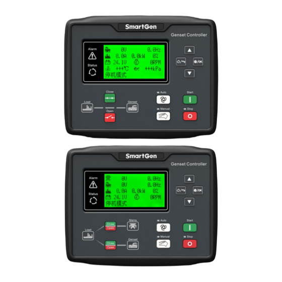
Page 10: Controller Panel
HGM6100LT Series Genset Controller User Manual 4.2 CONTROLLER PANEL Fig.1 - HGM6110LT Front Panel Indication Fig.2 - HGM6120LT Front Panel Indication Note: Partial indicator states Alarm Lamp: slowly blink when warning alarms; fast blink when shutdown alarms; won’t illuminate when there is no alarm. -
Page 11: Automatic Start/Stop Operation
HGM6100LT Series Genset Controller User Manual 4.3 AUTOMATIC START/STOP OPERATION Auto mode is activated by pressing the , LED indicator beside the button is illuminating which confirms this action. Starting Sequence, HGM6120LT: When mains is abnormal (over/under voltage, lack of phase), enter into ―Mains Abnormal Delay‖... -
Page 12: Manual Start/Stop Operation
HGM6100LT Series Genset Controller User Manual 4.4 MANUAL START/STOP OPERATION HGM6120LT, Manual Mode is active when press and its indicator illuminates. Under both of the modes, press to start genset, it can automatically detect crank disconnect and accelerate to high speed running. If there is high temperature, low oil pressure, over speed and abnormal voltage during genset running, controller can protect genset to stop (detail procedures please refer to No.4~9 of Auto start operation). -
Page 13: Protection
HGM6100LT Series Genset Controller User Manual 5 PROTECTION 5.1 WARNINGS When controller detects the warning signal, the genset only alarm and not stop. The alarms are displayed in LCD. Table 4 – Controller Warning Alarms Items Description When the speed of genset is 0 and speed loss delay is 0, controller will Loss of Speed Signal send warning alarm signal and it will be displayed in LCD. -
Page 14: Shutdown Alarms
HGM6100LT Series Genset Controller User Manual Items Description When the oil pressure of genset is less than threshold and Enabled Low Oil Pressure Stop Inhibited or Input Low Oil Pressure Stop Inhibited is 13 Low Pressure Warn active, controller will send warning alarm signal and it will be displayed in LCD. - Page 15 HGM6100LT Series Genset Controller User Manual Items Description Alarm send a stop alarm signal and it will be displayed in LCD. Within set start times, if failed to start, controller will send a stop alarm 10 Failed To Start Alarm signal and it will be displayed in LCD.
-
Page 16: Connections
HGM6100LT Series Genset Controller User Manual 6 CONNECTIONS Compared with HGM6120LT, HGM6110LT doesn’t have 3-phase input terminal of mains voltage. The back panel of HGM6120LT is as below. Fig.3 – Controller Rare Panel Drawing Table 6 – Terminal Connection Description... - Page 17 HGM6100LT Series Genset Controller User Manual Function Cable Size Description not connected. Speed sensor input Connected to Speed sensor, shielding line is Speed sensor input, B- is 0.5mm recommended. connected. Connect to water /cylinder temp. Temp. Sensor Input 1.0mm resistance type sensor...
-
Page 18: Parameter Range And Definition
HGM6100LT Series Genset Controller User Manual 7 PARAMETER RANGE AND DEFINITION 7.1 PARAMETER CONTENT AND RANGE TABLE Table 7 – Parameter Content and Range Items Range Default Description Mains Normal Delay (0-3600)s The delay from abnormal to normal or from Mains Abnormal normal to abnormal. - Page 19 HGM6100LT Series Genset Controller User Manual Items Range Default Description from end of idle delay to gen-set at rest; if not 0, it is from end of ETS solenoid delay to gen-set at rest. Mains’ or generator’s switch closing pulse...
- Page 20 HGM6100LT Series Genset Controller User Manual Items Range Default Description port) When fuel level sensor value under this point Low Level Warning 30(25) (0-100)% and remains for 10s, genset send out warning Value alarm, only warn but not shutdown. Loss Of Speed Signal...
- Page 21 HGM6100LT Series Genset Controller User Manual Items Range Default Description See table 9 49(44) Active Type (0-1) Factory default: close to Activate 50(45) Delay (0-20.0)s 51(46) Digital Input 3 (0-23) Factory default: Remote start. See table 9 52(47) Active Type...
- Page 22 HGM6100LT Series Genset Controller User Manual Items Range Default Description Temp. Sensor Open 74(69) (0-2) Circuit Action 0: Not used; 1: Warn; 2: Shutdown Oil Pressure Sensor 75(70) (0-2) Open Circuit Action When disconnect conditions include oil pressure and engine oil pressure is higher...
- Page 23 HGM6100LT Series Genset Controller User Manual Items Range Default Description unit enters the high-speed warm-up. It is the speed-drop pulse output time, when 92(87) Speed Drop Pulse (0-20.0)s the unit enters the stop idling. When fuel level of external level sensor falls...
- Page 24 HGM6100LT Series Genset Controller User Manual Note5: If default password (0318) isn’t changed, it doesn’t need to input when configuring parameters via PC software; if the password is changed for the first time via PC software, it need to input password in password window.
-
Page 25: Programmable Output 1-4 Table
HGM6100LT Series Genset Controller User Manual 7.2 PROGRAMMABLE OUTPUT 1-4 TABLE Table 8 – Definition Content of Relay Output 1-4 Items Description Not Used Output is disabled when this item is selected. Including all shutdown alarm and warning alarm. When a warning alarm occurs, the alarm won’t self-latch;... -
Page 26: Programmable Input 1-5 Table
HGM6100LT Series Genset Controller User Manual Items Description Rising speed time is output while the unit entering into hi-speed Raise Speed Pulse warming up. Dropping speed time is output while the unit entering into stop Drop Speed Pulse idling. Engine type select Yuchai-LMB. When unit is standby, pump control output per 30 minutes. - Page 27 HGM6100LT Series Genset Controller User Manual Items Description ―Remote Mode‖ is displayed on LCD. Remote module can switch module mode and start/stop operation via panel buttons. Connect to ―failed to charge output‖ of the charger. Charge Alt Fail IN All buttons in panel is inactive except...
-
Page 28: Sensor Selection
HGM6100LT Series Genset Controller User Manual 7.4 SENSOR SELECTION Table 10 – Sensors Selection Items Content Description 0 Not used 1 User Configured (Resistance Type) 2 VDO 3 SGH 4SGD 5 CURTIS 6 DATCON Defined input resistance range is Temperature 7 VOLVO-EC 0Ω~6000Ω, factory default is SGD... -
Page 29: Conditions Of Crank Disconnect (Table 5)
HGM6100LT Series Genset Controller User Manual 7.5 CONDITIONS OF CRANK DISCONNECT (TABLE 5) Table 11 – Crank Disconnect Conditions Content Speed Generator frequency Speed + Generator frequency Speed + Oil pressure Generator frequency + Oil pressure Generator frequency + Speed + Oil pressure Oil pressure 1) There are 3 kinds of crank disconnect conditions. -
Page 30: Parameter Setting
HGM6100LT Series Genset Controller User Manual 8 PARAMETER SETTING After controller powered on, press to enter into the parameters setting menu: 1. Set Parameters 2. Information 3. Set Language 4. Event Log 5. ECU DM2 6. Maintenance — Parameters Setting All items in table7 can be set after inputting password ―0318‖. -
Page 31: Sensor Setting
HGM6100LT Series Genset Controller User Manual Press ) can adjust LCD contract. Adjustment range is 0-7. 9 SENSOR SETTING — When choosing sensor, standard of sensor curve will be needed. If temperature sensor is set as SGH (120º C resistor type), sensor curve should be SGH (120 C resistor type);... -
Page 32: Commissioning
— When mains abnormal again, genset will start automatically and into normal running, send signal to make gens close, transfer ATS and make genset take load. If it not likes this, please check connections of ATS according to this manual. — If there are any other questions, please contact SmartGen’s service. HGM6100LT Genset Controller 2018-10-26 Version 1.0... -
Page 33: Typical Application
HGM6100LT Series Genset Controller User Manual 11 TYPICAL APPLICATION Fig.4 - HGM6110LT Typical Application Diagram Fig.5 - HGM6120LT Typical Application Diagram HGM6100LT Genset Controller 2018-10-26 Version 1.0 Page 33 of 45... - Page 34 HGM6100LT Series Genset Controller User Manual Fig.6 - Single Phase 2 Wire Fig.7 - 2 Phase 3 Wire Note: Recommend that the output of crank and Fuel expand high capacity relay. HGM6100LT Genset Controller 2018-10-26 Version 1.0 Page 34 of 45...
-
Page 35: Installation
12.2 OVERALL DIMENSION AND PANEL CUTOUT Fig.8 – Case and Overall Dimensions HGM6100LT series controller can be applicable to (8~35) VDC battery voltage. Battery negative must be reliably connected to engine shell. The connection between controller power (B+ and B-) and battery (B+ and B-) should not be less than 2.5mm... - Page 36 HGM6100LT Series Genset Controller User Manual current and active power may be incorrect. Note: A. Icom must connect to battery cathode of the controller. B. When there is load current, open circuit is inhibited in the CT secondary side. 5) Dielectric Strength Test When the controller has been installed in the control panel, during the test please disconnect all the terminals, in case high voltage damages the controller.
-
Page 37: Connections Of Controller With J1939 Engine
HGM6100LT Series Genset Controller User Manual 13 CONNECTIONS OF CONTROLLER WITH J1939 ENGINE 13.1 CUMMINS ISB/ISBE Table13 – Connector B Terminals of controller Connector B Remark Set configurable output 1 as ―Fuel Relay Programmable output port 1 Output‖ Start relay output... -
Page 38: Cummins Qsm11 (Import)
HGM6100LT Series Genset Controller User Manual 13.3 CUMMINS QSM11 (IMPORT) It is suitable for CM570 engine control mode. Engine type is QSM11 G1, QSM11 G2. Table 17 – C1 Connector Terminals of controller C1 connector Remark Set configurable output 1 as ―Fuel Relay Output‖. -
Page 39: Cummins Gcs-Modbus
HGM6100LT Series Genset Controller User Manual 13.5 CUMMINS GCS-MODBUS It is suitable for GCS engine control module. Use RS485-MODBUS to read information of engine. Engine types are QSX15, QST30, QSK23 / 45/60/78 and so on. Table 21 – D-SUB Connector 6... -
Page 40: Detroit Diesel Ddec Iii / Iv
HGM6100LT Series Genset Controller User Manual Terminals of controller OEM connector of engine Remark connect with 41 for 0.1s during high-speed warming of controller via external expansion relay. CAN_SCR CAN communication shielding line. Using impedance 120Ω connecting line CAN(H) Using impedance 120Ω connecting line... -
Page 41: John Deere
HGM6100LT Series Genset Controller User Manual 13.10 JOHN DEERE Table 27 – 21 Pins Connector Terminals of controller 21 pins connector Remark Set configurable output 1 as ―Fuel Relay Programmable output1 Output‖. Start relay output CAN communication shielding line CAN_SCR Using impedance 120Ω... -
Page 42: Mtu Adec(Sam Module)
HGM6100LT Series Genset Controller User Manual 13.13 MTU ADEC(SAM MODULE) It is suitable for MTU engine with ADEC (ECU7) and SAM module. Table 31 – ADEC (X1 port) Terminals of controller ADEC (X1port) Remark Set configurable output 1 as ―Fuel Relay... -
Page 43: Volvo Edc3
HGM6100LT Series Genset Controller User Manual 13.16 VOLVO EDC3 Suitable engine control mode is TAD1240, TAD1241, and TAD1242. Table 35 – ―Stand alone‖ Connector ―Stand alone‖ connector Terminals of controller Remark Set configurable output 1 as ―Fuel Relay Programmable output1 Output‖... -
Page 44: Volvo-Ems2
HGM6100LT Series Genset Controller User Manual 13.18 VOLVO-EMS2 Volvo Engine types are TAD734, TAD940, TAD941, TAD1640, TAD1641, and TAD1642. Table 38 – Engine CAN Port Engine’s CAN port Terminals of controller Remark ECU stop Programmable output1 Configurable output 1 ―ECU stop‖... -
Page 45: Fault Finding
HGM6100LT Series Genset Controller User Manual Engine type: GTSC1 NOTE: If there is any question of connection between controller and ECU communication, please feel free to contact SmartGen service. 14 FAULT FINDING Table 42 – Fault Finding Symptoms Possible Solutions Check starting battery;...
Need help?
Do you have a question about the HGM6100LT SERIES and is the answer not in the manual?
Questions and answers