Extron electronics DMP 64 Plus User Manual
Audio products mixers and processors
Hide thumbs
Also See for DMP 64 Plus:
- Setup manual (4 pages) ,
- Configuration manual (28 pages) ,
- Setup manual (21 pages)

Related Manuals for Extron electronics DMP 64 Plus


Summary of Contents for Extron electronics DMP 64 Plus
- Page 1 User Guide Audio Products Mixers and Processors DMP 64 Plus ProDSP Digital Matrix Processor 68-3291-01 Rev. C 10 22...
- Page 2 Safety Instructions Safety Instructions • English WARNING: This symbol, , when used on the product, is intended to alert the user of the presence of uninsulated dangerous voltage within the product’s enclosure that may present a risk of electric shock. ATTENTION: This symbol, , when used on the product, is intended...
- Page 3 Copyright © 2019-2022 Extron. All rights reserved. www.extron.com Trademarks All trademarks mentioned in this guide are the properties of their respective owners. The following registered trademarks ( ® ), registered service marks ( ), and trademarks ( ) are the property of RGB Systems, Inc. or Extron (see the current list of trademarks on the Terms of Use page at www.extron.com):...
- Page 4 FCC Class A Notice This equipment has been tested and found to comply with the limits for a Class A digital device, pursuant to part 15 of the FCC rules. The Class A limits provide reasonable protection against harmful interference when the equipment is operated in a commercial environment.
- Page 5 Conventions Used in this Guide Notifications The following notifications are used in this guide: CAUTION: Risk of minor personal injury. ATTENTION : Risque de blessure mineure. ATTENTION: • Risk of property damage. • Risque de dommages matériels. NOTE: A note draws attention to important information. A tip provides a suggestion to make working with the application easier.
-
Page 6: Table Of Contents
About this Guide ..........1 Overview ............21 DMP 64 Plus Models ........... 1 Downloading and Installing Dante Controller ..21 About the DMP 64 Plus ........1 Configuring the DMP 64 Plus in Dante Controller ............22 Features .............. 2 Device Name .......... - Page 7 Automixer OIDs ..........64 Mix-point OIDs..........66 Internal Web Pages ........74 Accessing the Embedded Web Pages ....74 DMP 64 Plus Default Web Page ....... 75 Communication Settings ....... 75 RS-232 Settings ........... 76 Device Info ............. 76 Date/Time Settings ........77 Passwords.............
-
Page 8: Introduction
DMP 64 Plus C V AT 6x4 Digital Matrix Processor w/ AEC, VoIP, and Dante About the DMP 64 Plus The Extron DMP 64 Plus Digital Audio Matrix Processor is a 6x4 audio mixer with broad I/O expansion capabilities, including: •... -
Page 9: Features
DMP 64 Plus input and output expansion capabilities. DMP 64 Plus V models can register up to 8 VoIP lines per device. The DMP 64 Plus V can function as a VoIP interface, removing the need for dedicated VoIP hardware. The DMP 64 Plus has no front panel controls. -
Page 10: Application Diagram
VoIP PBX. • Extensive mix matrixing in every DMP 64 Plus allows all inputs to be discretely routed to any or all outputs — The mix matrix allows all main inputs, aux inputs, Dante inputs and virtual bus returns to be discretely routed to any or all of the analog outputs, aux outputs, Dante outputs and the virtual bus sends. -
Page 11: Installation
• Reset Modes Installation Overview Follow these steps to install and set up the DMP 64 Plus for operation: Disconnect power from the DMP, and turn off all devices connected to the DMP. If desired, mount the DMP (see Equipment Mounting on page 90). - Page 12 (V models only) (see TP Cable Termination for Ethernet Communication page 11 for wiring details). The host PC or control system and the DMP 64 Plus must be connected to the same network. The ports have two LEDs: Link LED — Lights green steadily to indicate a LAN connection.
- Page 13 Connect a Windows or Mac computer to this USB mini-B port to interface with the DMP 64 Plus as a USB audio device (see Configure USB Audio on page 17 for details on configuring the USB audio). Audio sample rate is 48 kHz/16 bit.
- Page 14 Balanced Output Unbalanced Output 3-pole Audio OUTPUT Wiring NO Ground Here Ring Sleeve Sleeve NO Ground Here Ring Sleeve Sleeve Balanced Output Unbalanced Output 6-pole Audio OUTPUT Wiring Figure 7. 3-pole and 6-pole Audio Output Wiring DMP 64 Plus • Installation...
-
Page 15: Front Panel Features
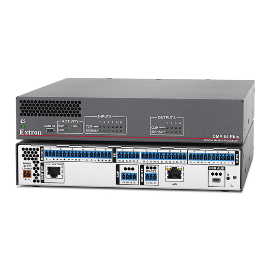
Figure 8. DMP 64 Plus Front Panel Power LED — Blinks during boot up and lights steadily when the DMP 64 Plus is operational. USB Config port — One USB type mini-B port is used for configuration. This port can also be used for firmware updates.. -
Page 16: Connection Details
Power Supply Wiring A 12 VDC, 2.0 A power supply is provided with the DMP 64 Plus. Follow the instructions and figure 9 to wire the provided 2-pole captive screw connector to your power supply. - Page 17 To verify the polarity before connection, plug in the power supply with no load • and check the output with a voltmeter. • Pour vérifier la polarité avant la connexion, brancher l’alimentation hors charge et mesurer sa sortie avec un voltmètre. DMP 64 Plus • Installation...
-
Page 18: Tp Cable Termination For Ethernet Communication
NOTE: The reset modes listed in the Reset Modes table close all IP connections, Telnet connections, and sockets. DMP 64 Plus • Installation... - Page 19 • Any inserted or active DSP removed. • All preset and group master memory is cleared. NOTE: *For modes 4 and 5, nothing happens if the momentary press does not occur within 1 second. DMP 64 Plus • Installation...
-
Page 20: Dsp Configurator Software
Extron DSP Configurator Software is the main user interface for control and management of the Extron DMP 64 Plus and all of its audio functions, including mixing, gain, dynamics, filtering, delay, microphone ducking, and monitoring. This section describes the Extron DSP Configurator software and covers the following topics: •... - Page 21 To install via Toolbelt, see the Toolbelt Help File. To install via Firmware Loader, see the Firmware Loader Help File. NOTE: Firmware Loader can also be open from DSP Configurator in the Tools menu, if installed (see Firmware Loader on page 17). DMP 64 Plus • DSP Configurator Software...
-
Page 22: Connecting To Dsp Configurator
The Extron DSP Configurator splash screen opens (see figure 15). From the DSP Configurator splash screen drop-down list ( ), select the DMP 64 Plus being connected to the host PC and click OK ( Figure 15. DSP Configurator Accessing the DSP Configurator Help File... -
Page 23: Menu Bar
Device Manager on page 17). • Backup — Recalls and transfers all partial presets of a DMP 64 Plus to the configuration file or template file within DSP Configurator. NOTES: Configuration files have an .EDC file extension and template files have an .EDCT file •... -
Page 24: Tools
Options dialog box to configure DSP Configurator appearance, • Options — Opens the default settings, DSP value defaults, and so on. • Network Audio Control — Opens the Dante Controller application by Audinate for routing audio over a Dante network. DMP 64 Plus • DSP Configurator Software... -
Page 25: Window
Secondary unit. • Phone Dialer — Configure and test the DMP 64 Plus VoIP line. DSP Configurator must be connected Live to a DMP 64 Plus V-model in order for the Phone Dialer dialog to be opened. Window The Window menu offers the standard Windows Window Menu options such as Cascade and Close All Windows. -
Page 26: Live And Emulate Panel
Live and Emulate Buttons Live Mode Enter Live mode to connect to a DMP 64 Plus and push or pull configurations between the device and host PC. In Live mode, changes made in DSP Configurator are directly applied to the device. Additionally, presets and macros can be created and stored on the device. - Page 27 While in Emulate mode, DSP Configurator is functioning in an “offline” state. Changes made to the configuration file are not applied to a DMP 64 Plus. In Emulate mode, the user can create and configure the software as though a device was connected, except for any actions that require direct connection to the device or information that is stored only on the device.
-
Page 28: Dante Controller
• • Dante Troubleshooting Overview DMP 64 Plus AT devices (DMP 64 Plus C AT and C V AT) use Dante technology by Audinate to provide high performance digital audio networking over standard TCP/IP ® networks. The Dante Controller software application is used to route audio on the network. -
Page 29: Configuring The Dmp 64 Plus In Dante Controller
Configuring the DMP 64 Plus in Dante Controller Use a standard Ethernet cable to connect the DMP 64 Plus to a Dante network via the rear panel AT port (see figure 2, on page 4) and power the device. Device Name Multiple devices on the same Dante network can present difficulty in identifying individual devices. -
Page 30: Dante Controller Naming Conventions
NOTE: Dante device naming can also be done via DSP Configurator (see Device Settings on page 17). Ensure that the control computer and a single DMP 64 Plus are connected to the same network. From the control computer Start menu select: All Programs > Audinate > Dante Controller > Dante Controller The Dante Controller - Network View screen opens. - Page 31 The Device View dialog populates with the selected DMP 64 Plus information (see figure 27). Figure 27. Populated Device View Dialog Box ) to open the Device Config page. Click the Device Config tab (see figure 28, Figure 28. Device Config Dialog Box In the Rename Device panel, enter the new name of the device in the text field.
-
Page 32: Renaming A Receiver Or Transmitter
( ). The DMP 64 Plus receivers are labelled EXP_In-01 through EXP_In-48 because the DMP 64 Plus can receive signal at the 48 EXP inputs. Follow the instructions on the next page to rename a receiver or transmitter. -
Page 33: Finding A Dante Device Ip Address
DMP 64 Plus in Dante Controller on page 23). NOTE: If the DMP 64 Plus has not been renamed, its default name consists of the product name followed by a hyphen, plus the last 6 digits of the device MAC address (for example, DMP64Plus-0ee8ee). -
Page 34: Physical Dante Network Setup
A physical network is required to share Dante audio channels between Dante-enabled devices like the DMP 64 Plus. Other Dante-enabled devices must be on the same physical network in order to communicate via Dante. A daisy chain topology can be used to connect multiple devices. -
Page 35: Dante Controller Operation
Controller for routing to other Dante devices. Routing Devices After the DMP 64 Plus is configured, the channels can be routed to the other Dante devices on the audio network. Channels transmitted to the network or received from the network are routed using the Dante Controller Routing tab on the Network View page (see figure 34... -
Page 36: Disconnecting Inputs From Outputs
Device level configuration such as sample rates, latency, and clock settings are saved instantly. Sending SIS Commands to Dante Audio Interface Devices through the DMP The DMP 64 Plus can be set to pass through SIS commands to connected Dante- controlled Extron devices (see Dante Control and Configuration on page 52 for SIS... - Page 37 To send an SIS command to an AXI device connected to a DMP 64 Plus: Connect the DMP and Dante-controlled devices to the same network via their AT ports Physical Dante Network Setup (see on page 27). Connect to the DMP via the DataViewer or HyperTerminal utility (see...
-
Page 38: Disconnecting Inputs From Outputs
Ethernet cable connecting the PC to the Dante network and restart Dante Controller. This can be enough for the software to reacquire the Dante network. If the problem persists, perform the following troubleshooting procedures in the order listed. DMP 64 Plus • Dante Controller... -
Page 39: Simplifying The Network For Troubleshooting
Enable DHCP on the remaining network connection. This forces the computer to acquire an IP address from the Dante interface. NOTE: A DHCP server must be on the network for DHCP to function correctly. DMP 64 Plus • Dante Controller... -
Page 40: Restarting Dante Controller
Click the Help icon in the upper-right corner of the Network View screen (see • figure 39, Select Help, then Online Help or Offline Help from the menu ( • • Press the <F1> key on the computer keyboard for online help or <Shift+F1> for offline help. DMP 64 Plus • Dante Controller... -
Page 41: Sis Configuration And Control
SIS Configuration and Control Use Simple Instruction Set (SIS) commands to configure the DMP 64 Plus. This section provides information about using those commands. Topics include: • Host Control Ports • Simple Instruction Set Control • Command and Response Table for SIS Commands •... -
Page 42: Establishing A Connection
Default IP Address To access the DMP 64 Plus via the LAN port (LAN 1 on V-models), the IP address, subnet mask, and the gateway address for the devices are needed. If the address have not been changed, the factory-specified defaults are: DHCP •... -
Page 43: Verbose Modes
• If the DMP 64 Plus is off and RS-232 connection is already set up (the PC is cabled to the DMP 64 Plus and a serial communication program such as DataViewer is open), the connected unit sends these messages via RS-232 when first powered on. -
Page 44: Password Prompt
“0” is the number zero and “O” is the capital letter “o”. Error Responses When the DMP 64 Plus is unable to execute the command, it returns an error response to the host. The error response codes and their descriptions are as follows: E10 –... -
Page 45: Simple Control Port Commands
The DMP 64 Plus rejects the following characters: {space (OK for names)} + ~ , @ = ‘ { } [ ] < > ` “ ; : \ ? - Page 46 Prefix (subnet mask bits) — Subnet is represented as a Prefix value of /16. Text up to 64 characters. Digital Input Status — = Logic low = Logic high Digital I/O Channel — through DMP 64 Plus• SIS Configuration and Control...
- Page 47 10 = Automix gate on (>1024) set high 11 = Automix gate on (>1024) set low Signal Presence 12 = Signal presence (>-40 dBFS) set high 13 = Signal presence (>-40 dBFS) set low DMP 64 Plus• SIS Configuration and Control...
- Page 48 -19.0 dB to 80 dB, (-180 to 800) in 0.1 dB increments. -100.0 dB to +12.0 dB, (-1000 to 120) in 0.1 dB increments. NOTE: The integers only need to be signed if they are a negative number. DMP 64 Plus• SIS Configuration and Control...
- Page 49 Line Number — Appearance Number — (where is originating two-party call) Phone Number — No spaces allowed. Valid characters are Return Code — = Ok = Fail Operating State — = Enable = Disable DMP 64 Plus• SIS Configuration and Control...
- Page 50 Hold Status — = Off = On hold Repeat Status — = Play once = Repeat Target OID — See Automixer OIDs on page 64. Mute/Phantom Power Status — = Disabled (default) = Enabled DMP 64 Plus• SIS Configuration and Control...
-
Page 51: Command And Response Table For Sis Commands
= Data Pacing: Specified in milliseconds between bytes. 0000-1000ms (default is 0 ms). For host port or ports, this value is ignored and always returns a 0. = Stop Bits: 1 (default) or 2. DMP 64 Plus • SIS Configuration and Control... - Page 52 Network Interface Card number 1 or 2 (only V-models have 2 NICs) Subnet 255.255.0.0 is represented as a Prefix value of /16. = Prefix (subnet mask bits): = DHCP Status: = off (default) = on DMP 64 Plus • SIS Configuration and Control...
- Page 53 •length space_remaining•bytes left Load file to user flash +UFfilesize, memory filename Retrieve file from user {responds with 4 bytes of file size and filenameSF flash memory unprocessed data in file} DMP 64 Plus • SIS Configuration and Control...
- Page 54 Disable SNMP port • X5^ *0PMAP PmapA *00000 KEY: 1024 = Ethernet Port Number: = Off, custom port numbers must be or higher = Network Interface Card #: = LAN 1, = LAN 2 DMP 64 Plus • SIS Configuration and Control...
- Page 55 Enable SNMP access E1SNMP SnmpE*1 Disable SNMP access E0SNMP SnmpE*0 View SNMP access X5! ] ESNMP setting KEY: = Text: Up to 64 characters. = SNMP Access: = Disabled (default), = Enabled DMP 64 Plus • SIS Configuration and Control...
- Page 56 I/O channel number. Signal Presence — Input number for signal presence monitoring. If is not specified, the input number defaults to the corresponding I/O channel number. DMP 64 Plus • SIS Configuration and Control...
- Page 57 (outputs through Aux inputs = EXP output number: through ~ , @ = ‘ [ ] { } < > ` “ : ; | \ = Name: Invalid characters = DMP 64 Plus • SIS Configuration and Control...
- Page 58 Get player repeat status X9* ] CPLY Playback finished Unsolicited Play KEY: = Player ID: through X4& = Play State: = Stopped = Playing = Repeat status: = Play once = Repeat DMP 64 Plus • SIS Configuration and Control...
- Page 59 = Macro step Dante Control and Configuration The following commands configure the DMP 64 Plus to listen for and pass through SIS commands meant for Extron endpoints controlled over Dante, such as AXI AT or NetPA Ultra AT devices. NOTE: The DMP must be set to Verbose mode 1/3 when using the Dante Control and Configuration commands.
- Page 60 Command ASCII command Response Additional description (host to device) (device to host) USB Call Status View USB 1 call status X9)] H1UPHN UphnH1* KEY: = Call status: = Inactive = Active DMP 64 Plus • SIS Configuration and Control...
-
Page 61: Command And Response Table For Dsp Sis Commands
Disable phantom power *0AU 1 through 8. Phantom power status KEY: = Target OID: Object ID (OID) Number Tables on page 61. = Phantom power status: = Disabled (default), = Enabled DMP 64 Plus • SIS Configuration and Control... - Page 62 Gain uses 10x multiplier (+10 dB = +). + or - goes after the number. = Group fader soft limit: dB value in 0.1 dB steps. Gain uses 10x multiplier (+10 dB = DMP 64 Plus • SIS Configuration and Control...
- Page 63 Values in the response can be (0.0 to -150.0 dBFS). • The order of the values is the numerical order of the OIDs/members in that group. KEY: = Group master meter group number: through DMP 64 Plus • SIS Configuration and Control...
- Page 64 Enable meter updates X7! ] KEY: = Target OID: Object ID (OID) Number Tables on page 61. = Update status: = Disabled = Enabled 1500 0000 = Meter level: -150.0 dBFS to 0.0 dBFS ( DMP 64 Plus • SIS Configuration and Control...
- Page 65 = disabled = signal threshold to monitor (-0.1 to -200.0 dBFS). X7& 0000 2000 -200.0 = Meter value: dBFS = Meter relative to threshold: = Above threshold = Equal to or below threshold DMP 64 Plus • SIS Configuration and Control...
-
Page 66: Command And Response Table For Voip Sis Commands
= Line number: 1 through 8 = Operating state: = Enable = Disable = Auto answer mode: = Disabled = Delay (seconds) = Follow SIP header = Delay value: Represents time in seconds. DMP 64 Plus • SIS Configuration and Control... - Page 67 = On hold = Outgoing HH:MM:SS = Duration: = Codec name: Alphanumeric characters only = Jitter in milliseconds = Packet drop count = Total packet count = Extension number: Valid characters are DMP 64 Plus • SIS Configuration and Control...
-
Page 68: Object Id (Oid) Number Tables
50111 Virtual Return E 50104 Virtual Return M 50112 Virtual Return F 50105 Virtual Return N 50113 Virtual Return G 50106 Virtual Return O 50114 Virtual Return H 50107 Virtual Return P 50115 DMP 64 Plus• SIS Configuration and Control... - Page 69 AT In 24 50223 EXP 16 50247 NOTES: Non-AT models only use the first 16 channels of the Expansion Bus. • • For AT models, the last 16 Expansion Bus channels are Expansion Inputs. DMP 64 Plus• SIS Configuration and Control...
-
Page 70: Output Path Oids
60027 EXP Output 5 60020 EXP Output 13 60028 EXP Output 6 60021 EXP Output 14 60029 EXP Output 7 60022 EXP Output 15 60030 EXP Output 8 60023 EXP Output 16 60031 DMP 64 Plus• SIS Configuration and Control... -
Page 71: Automixer Oids
Automixer 27 59046 Automixer 20 59039 Automixer 28 59047 Automixer 21 59040 Automixer 29 59048 Automixer 22 59041 Automixer 30 59049 Automixer 23 59042 Automixer 31 59050 Automixer 24 59043 Automixer 32 59051 DMP 64 Plus• SIS Configuration and Control... - Page 72 Automixer 43 59062 Automixer 36 59055 Automixer 44 59063 Automixer 37 59056 Automixer 45 59064 Automixer 38 59057 Automixer 46 59065 Automixer 39 59058 Automixer 47 59066 Automixer 40 59059 Automixer 48 59067 DMP 64 Plus• SIS Configuration and Control...
-
Page 73: Mix-Point Oids
21711 21712 21713 21714 21715 Aux 7 21800 21801 21802 21803 21808 21809 21810 21811 21812 21813 21814 21815 Aux 8 21900 21901 21902 21903 21908 21909 21910 21911 21912 21913 21914 21915 DMP 64 Plus• SIS Configuration and Control... - Page 74 23311 23312 23313 23314 23315 Rtn O 23400 23401 23402 23403 23408 23409 23410 23411 23412 23413 23414 23415 Rtn P 23500 23501 23502 23503 23508 23509 23510 23511 23512 23513 23514 23515 DMP 64 Plus• SIS Configuration and Control...
- Page 75 23417 23418 23419 23420 23421 23422 23423 23424 23425 23426 23427 23428 23429 22016 23431 Rtn P 23516 23517 23518 23519 23520 23521 23522 23523 23524 23525 23526 23527 23528 23529 23530 22016 DMP 64 Plus• SIS Configuration and Control...
- Page 76 26511 26512 26513 26514 26515 Exp 31 26600 26601 26602 26603 26608 26609 26610 26611 26612 26613 26614 26615 Exp 32 26700 26701 26702 26703 26708 26709 26710 26711 26712 26713 26714 26715 DMP 64 Plus• SIS Configuration and Control...
- Page 77 25033 25034 25035 25036 25037 25038 25039 25040 25041 25042 25043 25044 25045 25046 25047 Exp 16 25132 25133 25134 25135 25136 25137 25138 25139 25140 25141 25142 25143 25144 25145 25146 25147 DMP 64 Plus• SIS Configuration and Control...
- Page 78 28233 28234 28235 28236 28237 28238 28239 28240 28241 28242 28243 28244 28245 28246 28247 Exp 48 28332 28333 28334 28335 28336 28337 28338 28339 28340 28341 28342 28343 28344 28345 28346 28347 DMP 64 Plus• SIS Configuration and Control...
- Page 79 26617 26618 26619 26620 26621 26622 26623 26624 26625 26626 26627 26628 26629 26630 26631 Exp 32 26716 26717 26718 26719 26720 26721 26722 26723 26724 26725 26726 26727 26728 26729 26730 26731 DMP 64 Plus• SIS Configuration and Control...
- Page 80 28217 28218 28219 28220 28221 28222 28223 28224 28225 28226 28227 28228 28229 28230 28231 Exp 48 28316 28317 28318 28319 28320 28321 28322 28323 28324 28325 28326 28327 28328 28329 28330 28331 DMP 64 Plus• SIS Configuration and Control...
-
Page 81: Internal Web Pages
Internal Web Pages The DMP 64 Plus features an internal web server, displayed as a web page. Two web pages are available: one for general configuration and one for VoIP configuration (V-models only). The pages allows you to monitor and adjust certain settings of the DMP 64 Plus via LAN connection. -
Page 82: Dmp 64 Plus Default Web Page
DMP 64 Plus Default Web Page The DMP 64 Plus default internal web page provides an overall, read-only view of the device status, with some editable fields. Panels are: Communication Settings Device Info Passwords RS-232 Settings Date/Time Settings Figure 41. -
Page 83: Rs-232 Settings
(see figure 47). Click Upload to update the firmware. Figure 48. Choose File to Upload Click Cancel to keep the current firmware. NOTE: Refer to Software/Firmware Installation on page 13 for details on downloading the firmware. DMP 64 Plus • Internal Web Pages... -
Page 84: Date/Time Settings
An administrator password must be applied before a user password can be applied. • The factory configured password for this device has been set to the device serial number. Passwords are case sensitive. Performing a Reset to Factory Defaults removes the password. DMP 64 Plus • Internal Web Pages... -
Page 85: Dmp 64 Plus Voip Web Page
DMP 64 Plus VoIP Web Page The DMP 64 Plus VoIP web page consists of the following tabs for configuration (see figure 53): Figure 53. VoIP Web Page Tabs Home — Displays VoIP statuses and details. Network —Allows network configuration for the interface, QoS/LLDP-MED, transport, NAT traversal, and advanced settings. -
Page 86: Network Tab
) select the desired LAN/VoIP port to be used for VoIP network traffic. Options are LAN 1, LAN 2, and VLAN. NOTE: Only select VLAN when joining a tagged network port on the switch. DMP 64 Plus • Internal Web Pages... - Page 87 The QoS/LLDP-MED tab allows users to set the PCP (Priority Code Point) and Differentiated Services Code Point (DSCP) as well as enable or disable the Link Layer Discovery Protocol - Media Endpoint Discovery (LLDP-MED) (see figure 57). Figure 57. VoIP Network QoS/LLDP-MED Tab DMP 64 Plus • Internal Web Pages...
- Page 88 VLAN ID checkbox — Select to read the voice VLAN ID from the network and • automatically configure the DMP 64 Plus VLAN tag (VLAN must be selected as the interface for this feature to work) QoS PCP checkbox — Select to read PCP values from the network and automatically •...
- Page 89 Browse button to locate a certificate or private key on the host PC. Click Import to commit this certificate or key to the DMP 64 Plus. Click Export to save the current local certificate or key to the default download directory of the web browser on the host Server Certs —...
- Page 90 The default is disabled. • • When the Apply button is clicked, network services on the DMP 64 Plus restart. This process can take up to 30 seconds. To set the STUN Server as the NAT traversal method: From the NAT Traversal drop-down list ( ), select STUN Server.
- Page 91 The Set Defaults button sets the Start Port to 50000 and the End Port • to 50999. Outgoing Calls — Disabled by default. If required, click the checkbox to enable codec compatibility mode. DMP 64 Plus • Internal Web Pages...
-
Page 92: Line Tabs
NOTE: If no port number is specified by the user, 5060 is used by default. Click Apply ( ) to make the changes to the DMP 64 Plus (click Clear to clear all fields). Applying the changes does not initiate line registration with the call server. - Page 93 Auto-answer drop-down list — Select On or Off for auto-answer answer features. Delay (seconds) — If auto-answer is enabled, enter the amount of delay in seconds before the call is automatically answered. Apply button — Click to save and apply the changes DMP 64 Plus • Internal Web Pages...
-
Page 94: Logs Tab
Export button — Exports the contents of the log window to a text file. The exported text file is automatically stored in the default download directory of the web browser. NOTE: For more information regarding VoIP logs, refer to the DMP 64 Plus product page on www.extron.com. - Page 95 This is the amount of time between registration attempts in seconds. NOTES: The example above is set to 300 seconds (5 mins) between • reconnections attempts. Valid Range of values: 120 - 3600 • DMP 64 Plus • Internal Web Pages...
- Page 96 Click the Import button ( ) to update the DMP Plus Series with the new settings. A notification will appear once the settings have applied successfully. DMP 64 Plus • Internal Web Pages...
-
Page 97: Equipment Mounting
The DMP can be set on a table, mounted in a rack, or mounted under a desk or table. Tabletop Use Four adhesive rubber feet are included with the DMP 64 Plus. For tabletop use, attach one foot at each corner on the bottom of the unit, and place it where desired. - Page 98 Consignes UL pour le montage en rack Les consignes UL (« Underwriters Laboratories ») suivantes concernent l’installation en rack d’un boîtier DMP 64 Plus : ATTENTION: • Température ambiante élevée — En cas d’installation de l’équipement dans un rack fermé ou composé de plusieurs unités, la température du rack peut être supérieure à...
- Page 99 Extron Warranty Extron warrants this product against defects in materials and workmanship for a period of three years from the date of purchase. In the event of malfunction during the warranty period attributable directly to faulty workmanship and/ or materials, Extron will, at its option, repair or replace said products or components, to whatever extent it shall deem necessary to restore said product to proper operating condition, provided that it is returned within the warranty period, with proof of purchase and description of malfunction to: USA, Canada, South America,...
Need help?
Do you have a question about the DMP 64 Plus and is the answer not in the manual?
Questions and answers