Extron electronics DMP 64 Plus Setup Manual
Hide thumbs
Also See for DMP 64 Plus:
- Configuration manual (28 pages) ,
- User manual (99 pages) ,
- Setup manual (21 pages)
Table of Contents
Advertisement
Quick Links
DMP 64 Plus • Setup Guide
This guide provides basic instructions for an experienced technician to install the DMP 64 Plus ProDSP
For more information, specifications, and the user guide, see the DMP 64 Plus product page on www.extron.com.
Disconnect Power and Mount the DMP 64 Plus
Disconnect power from the DMP 64 Plus and turn off all devices that will be connected to it. The DMP 64 Plus is housed in a
half rack width, 9.5 inch deep, 1U high metal enclosure that can be rack mounted or placed on a table with the provided rubber
feet. Select a suitable mounting location, then choose an appropriate mounting option. Mounting information can be found in the
DMP 64 Plus User Guide on www.extron.com.
Make all external device connections before applying power.
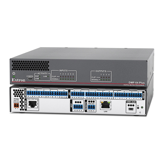
Rear Panel Connections
1
2
POWER
12V
2.0A MAX
A
B
Figure 1.
DMP 64 Plus C V AT Rear Panel
Power Input — Connect the included external 2-pole captive screw power supply.
A
EXP Port — Connect an EXP-enabled device to this RJ-45 port for a digital audio connection using Extron proprietary
B
protocol. Use the included one foot long shielded CAT 6 cable to connect two EXP-enabled devices to form a larger matrix
system. The expansion bus supports 16 bidirectional channels of audio (see the DMP 64 Plus User Guide for EXP bus
operation details).
AT Ports (AT models only) — Two RJ-45 ports form a Gigabit switch that interfaces with the AT bus. The AT expansion bus
C
uses Dante
protocol for digital audio networking and allows DMP 64 Plus AT models to connect with other Dante-enabled
®
devices to form a larger matrix (see the DMP 64 Plus User Guide for operation details).
NOTE:
Dante Controller software is required to configure the AT expansion bus. Dante Controller is available at
www.extron.com
ACP Panel Port — Use a 4-pole 3.5 mm captive screw connector to connect an ACP
D
control device for configuration via DSP Configurator (wiring shown to the right).
RS-232 Port — Use a 3.5 mm 3-pole captive screw connector to connect the host
E
RS-232 cable for bidirectional RS-232 (±5V) serial control (wiring shown to the right).
The default baud rate is 38400.
LAN Ports — One RJ-45 port (non-V models) or two RJ-45 ports (V models) are
F
available for control network traffic (all models) and VoIP network traffic (V models
only). On DMP 64 Plus V models, the LAN/VoIP ports have multiple configuration options (refer to the DMP 64 Plus User
Guide for configuration options). On the V models, by default, both control and VoIP traffic are transported on LAN/VoIP 1.
Port
LAN 1
LAN 2 (V models only)
G
USB Audio Port — Connect a Windows or Mac computer to this USB mini-B port to interface with the DMP 64 Plus as a 4x4
USB audio device (see the DMP 64 Plus User Guide for additional USB audio interfacing capabilities).
I
3
4
5
6
1
IN G O IN G O
1 (PRI) PoE+
2 (SEC)
+V
C
(see the DMP 64 Plus User Guide for instructions on installation and operation).
Default IP Address
Default Subnet Mask Default Gateway
192.168.254.254
255.255.255.0
192.168.1.254
255.255.255.0
J
2
3
4
5
6
IN G O IN G O
IN G O IN G O
RS-232
+S -S
G
Tx
Rx G
1
D
E
0.0.0.0
0.0.0.0
Digital Matrix Processor.
™
K
1
2
3
4
USB AUD
R
2
C V AT
F
G
H
+V
+12 VDC
+S
+ Signal
- Signal
-S
G
Ground
Tx
Transmit
Rx
Receive
G
Ground
Default DHCP
OFF
OFF
RS-232
Tx Rx G
1
Advertisement
Table of Contents

Related Manuals for Extron electronics DMP 64 Plus


Summary of Contents for Extron electronics DMP 64 Plus
-
Page 1: Rear Panel Connections
Disconnect Power and Mount the DMP 64 Plus Disconnect power from the DMP 64 Plus and turn off all devices that will be connected to it. The DMP 64 Plus is housed in a half rack width, 9.5 inch deep, 1U high metal enclosure that can be rack mounted or placed on a table with the provided rubber feet. -
Page 2: Front Panel Features
DMP 64 Plus • Setup Guide (Continued) Reset Button and LED — The reset button returns the DMP 64 Plus to different tiers of default states. When using the reset function, the LED blinks to signify the different reset modes. When not using the reset function, the LED operates as a power indicator and matches the front panel power LED (see the Reset Modes section of the DMP 64 Plus User Guide for more information on the different reset modes). - Page 3 DMP 64 Plus Configuration When power is connected to the DMP 64 Plus and the rest of the audio system, audio output can easily be tailored to any listening environment. When configuration is required, changes are made using DSP Configurator.
- Page 4 Configure Dante Device Settings: Dante settings on all DMP 64 Plus AT models can be configured from DSP Configurator. The Dante device can be named here, which aids in device identification in the Dante Controller software when there are multiple Dante devices on the audio network.
Need help?
Do you have a question about the DMP 64 Plus and is the answer not in the manual?
Questions and answers