Sign In
Upload
Download
Table of Contents
Contents
Add to my manuals
Delete from my manuals
Share
URL of this page:
HTML Link:
Bookmark this page
Add
Manual will be automatically added to "My Manuals"
Print this page
×
Bookmark added
×
Added to my manuals
Manuals
Brands
RGBlink Manuals
Switch
D Series
User manual
RGBlink D Series User Manual
Presentation switcher & seamless scaler
Hide thumbs
Also See for D Series
:
User manual
(53 pages)
1
Table Of Contents
2
3
4
5
6
7
8
9
10
11
12
13
14
15
16
17
18
19
20
21
22
23
24
25
26
27
28
29
30
31
32
33
34
35
36
37
38
39
40
41
42
43
44
45
46
47
48
49
50
51
52
53
54
55
56
57
58
59
60
61
62
63
64
65
66
67
68
69
70
71
72
73
74
75
76
77
78
79
80
81
82
83
84
85
86
87
88
89
90
91
92
93
94
page
of
94
Go
/
94
Contents
Table of Contents
Troubleshooting
Bookmarks
Table of Contents
Contents
Table of Contents
Declarations
Fcc/Warranty
Installation Safety Summary
Operators Safety Summary
Chapter 1 Your Product
In the Box
Product Overview
Back Panel
Front Panel
Dimension
Chapter 2 Installing Your Product
Plugging in Signals
Plugging in Main Power
Turning on Your Product
Chapter 3 Using Your Product
Using the MENU Button
Understanding the MENU Structure
Using the Menu
Understanding the Display
Understanding the Main Menu
Input Menu
Output Menu
Custom Formats Menu
Views Menu
Transition Menu
System Menu
Logo Menu
Display Setup Menu
Test Pattern Menu
Tech Support Menu
Factory Reset Menu
System Operation Mode
System Modes
Set the System Operation Mode
Set the Output Resolution
Select the Output Resolution
Custom the Output Resolution
Set the LED Display Connection
Capture LOGO
Using LOGO Button
Saving Views
Recall Saved Settings
Chapter 4 Controlling Your Processor Remotely
Using the Windows Control Program
Set up Communication
Use
Using the D2 App for Android & Ios
Connecting to an Ethernet Network
Using a D2 with WEB Option
Chapter 5 Ordering Codes
Product
Options
Output Options
Accessories
Sender Cards
Chapter 6 Support
Questions and Troubleshooting
OLED Screen Prompts "No Core Board
No Display on LED Screen When Output HDMI to Sending Card, DVI Monitors or DVI Projectors
Flash Point on LED Display When Output
Android or Ios APP Cannot Connect
VGA Input Offset or Cannot be Full Size Shown
Show Blurred Screen When Rotate for I System Input
Can't Do Split for I System Input
Show Black Lines or Blurred Screen for DP Input
Show Upgrade Error after Upgrade MCU Program
Software Upgrade Failed
Contact Us
Chapter 7 Appendix
Specification
Software Upgrade
Installing Options
Terms & Definitions
Revision History
Advertisement
Quick Links
Download this manual
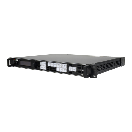
D2
USER MANUAL
Article No: RGB-RD-UM-D2 E010
Revision No: V2.0
Table of
Contents
Previous
Page
Next
Page
1
2
3
4
5
Advertisement
Table of Contents
Need help?
Do you have a question about the D Series and is the answer not in the manual?
Ask a question
Questions and answers
Related Manuals for RGBlink D Series
Media Converter RGBlink D8 User Manual
(53 pages)
Switch RGBlink D2 User Manual
Presentation switcher & seamless scaler (94 pages)
Switch RGBlink VSP 1314 User Manual
(76 pages)
Switch RGBlink mini User Manual
(48 pages)
Switch RGBlink Mini Quick Start Manual
(35 pages)
Switch RGBlink mini-edge Quick Start Manual
5 channel all-in-one switcher (26 pages)
Switch RGBlink mini-pro v3 Quick Start Manual
Streaming switcher (14 pages)
Switch RGBlink mini-pro Faq
(3 pages)
Switch RGBlink VENUS X1 PRO-E User Manual
(69 pages)
Switch RGBlink Mini Pro Quick Start Manual
(35 pages)
Switch RGBlink mini-ISO Quick Start Manual
10-channel all-in-one switcher (21 pages)
Switch RGBlink mini-ISO User Manual
(72 pages)
Switch RGBlink VSP 628PRO User Manual
(93 pages)
Switch RGBlink mini Quick Start Manual
Video processing for any scale (35 pages)
Switch RGBlink C1US User Manual
(79 pages)
Switch RGBlink M2 User Manual
(80 pages)
This manual is also suitable for:
D2
Table of Contents
Print
Rename the bookmark
Delete bookmark?
Delete from my manuals?
Login
Sign In
OR
Sign in with Facebook
Sign in with Google
Upload manual
Upload from disk
Upload from URL


Need help?
Do you have a question about the D Series and is the answer not in the manual?
Questions and answers