Table of Contents
Advertisement
Quick Links
Advertisement
Table of Contents

Related Manuals for RGBlink VENUS X1 PRO-E


Summary of Contents for RGBlink VENUS X1 PRO-E
- Page 1 VENUS X1PRO-E USER MANUAL Article No: RGB-RD-UM-X1PRO-E E001 Revision No: V1.1...
-
Page 2: Table Of Contents
CONTENTS CONTENTS................................ 1 Declarations..............................3 FCC/Warranty............................3 Operators Safety Summary........................4 Installation Safety Summary........................4 Chapter 1 Your Product............................ 6 1.1 In the Box............................6 1.2 Product Overview..........................7 1.2.1 Rear Panel..........................8 1.2.2 Front Panel..........................10 1.2.3 Dimension..........................12 Chapter 2 Installing Your Product........................13 2.1 Plugging in Signals..........................13 2.2 Plugging in Main Power........................ - Page 3 4.2.1 Input Options........................45 4.2.2 Output Options........................45 Chapter 5 Support ............................46 5.1 Questions and Troubleshooting.......................46 5.2 Contact Us............................48 Chapter 6 Appendix............................49 6.1 Specification.............................49 6.2 Software Upgrade..........................55 6.2.1Use XTOOL to upgrade the software..................55 6.2.2 Upgrade the software by USB disk..................62 6.3 Terms &...
-
Page 4: Declarations
RGBlink. If the purchaser or a third party carries out modifications or repairs on goods delivered by RGBlink, or if the goods are handled incorrectly, in particular if the systems are commissioned operated incorrectly or if, after the transfer of risks, the goods are subject to influences not agreed upon in the contract, all guarantee claims of the purchaser will be rendered invalid. -
Page 5: Operators Safety Summary
manual must be complied with by the customer. Operators Safety Summary The general safety information in this summary is for operating personnel. Do Not Remove Covers or Panels There are no user-serviceable parts within the unit. Removal of the top cover will expose dangerous voltages. -
Page 6: Unpacking And Inspection
The AC Socket-outlet should be installed near the equipment and be easily accessible. Unpacking and Inspection Before opening VENUS X1PRO-E processor shipping box, inspect it for damage. If you find any damage, notify the shipping carrier immediately for all claims adjustments. As you open the box, compare its contents against the packing slip. -
Page 7: Chapter 1 Your Product
Chapter 1: Your Product Chapter 1 Your Product 1.1 In the Box AC Power Cord DVI Cable DB9 to RJ11 Cable Screw Driver Antistatic Bag Note: AC Power Cable supplied as standard according to destination market. Screw driver color is random. VENUS X1PRO-E User Manual... -
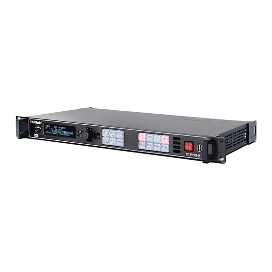
Page 8: Product Overview
Chapter 1: Your Product 1.2 Product Overview Professional 4K scaling and switching. VENUS X1PRO-E enables 4K switching, scaling and signal distribution to 2k display devices. It supports up to 4K input signals with Dual Link DVI, HDMI and Display Port. With independent scaling for each output, support Matrix for input and output, up to 8K1K or 4K2K pixel-to- pixel output. -
Page 9: Rear Panel
Chapter 1: Your Product 1.2.1 Rear Panel Input Connectors DVI-I DVI Standard DVI signals can be input, compatible HDMI1.3 4K DVI2 IN(HDMI) Standard DVI and 4K DVI signals can be input, compatible HDMI1.4 & 4K HDMI signals. 4K DP IN Standard DisplayPort and 4K DisplayPort signals can be input. -
Page 10: Power Connection
Chapter 1: Your Product Power Connection Power Switch Illuminated power switch. IEC – Power Input Main power input AC 85-264V Max 65W. VENUS X1PRO-E User Manual... -
Page 11: Front Panel
Chapter 1: Your Product 1.2.2 Front Panel Display OLED Display: Displays current status of the product, and for feature selections provides interactive choices in conjunction with buttons on the front panel. Multi-Function Buttons Rotary Button: This button used for menu selections and confirmation. Illuminated Buttons MENU Button Menu and back button. - Page 12 Chapter 1: Your Product values such as resolution and size. LOGO Button LOGO load &LOGO Capture shortcut button. OUT BRIGHT Shortcut button for output Setting, output Brightness Setting, and 4K Input Signal switch. SPLIT Button Split function button. LOAD Button Restores/Loads all current settings with the VENUS X1PRO-E from 1 of the 24 available slots.
-
Page 13: Dimension
Chapter 1: Your Product 1.2.3 Dimension Following is the dimension of VENUS X1PRO-E for your reference: VENUS X1PRO-E User Manual... -
Page 14: Chapter 2 Installing Your Product
Chapter 2 Installing Your Product 2.1 Plugging in Signals Connect signals to the product (ensure all devices are powered off first). Tighten connector screws/locks where provided. For connector protection and for additional cable support this product is fitted with protection frames on either side of the device. - Page 15 Chapter 2: Installing Your Product VENUS X1PRO-E Init Device Finished! Input 1 DVI1:NO INPUT SV: 0.99 SN:1397 System Mode :Standard Output Resolution :720x480x60 VENUS X1PRO-E User Manual...
-
Page 16: Chapter 3 Using Your Product
Chapter 3 Using Your Product 3.1 Using the MENU Button Push the [MENU] button to enter the menu display. Turn the rotary knob to navigate to the menu item required. The symbol shows the current item. Push the knob to select and enter into the menu item. As shown in the figure below: VENUS X1PRO-E User Manual... -
Page 17: Understanding The Menu Structure
Chapter 3: Using Your Product 3.2 Understanding the MENU Structure The MENU structure is shown in the figure below: VENUS X1PRO-E User Manual... -
Page 18: Using The Menu
Chapter 3: Using Your Product 3.3 Using the Menu Use the menu system for convenient and intuitive operation. VENUS X1PRO-E OLED display shows the menu items. The OLED display will show the default state when the menu is not in use, or the operation has timed out. -
Page 19: Understanding The Main Menu
Chapter 3: Using Your Product menu. System Mode Show the default system mode. Output Resolution Show the current output resolution. To configure output resolutions, use the OUTPUT menu. A wide range of resolutions are supported – refer to Specification. If a # symbol is show after the resolution, then a custom resolution is being used. 3.3.2 Understanding the Main Menu Push the MENU button in the default state and turn the rotary knob, the OLED display will show the main menus as below:... -
Page 20: Advanced Menu
Chapter 3: Using Your Product Select standard resolution or custom the resolution. Preview Mode Four Presentation Modes for selection. For details, please refer to Preview Mode. Stand Alone Setting four DVI Alone output and EDID setting. Mode For details, please refer to Stand Alone Mode. - Page 21 Chapter 3: Using Your Product Image to left and right zoom. Zoom Centre Image from center to the edges zoom. Mask Mask Top Setting Image top corp value. Mask Bottom Setting Image bottom corp value Mask Left Setting Image left corp value Mask Right Setting Image right corp value Reset Mask...
- Page 22 Chapter 3: Using Your Product Reset Parameters If image quality distorts by improper operation, it can be recover by reset. LOGO Load Select Layer Select layer A, B, C or D. LOGO Select Select LOGO 1 to LOGO 10. LOGO On/Off Enable or disable LOGO load function.
-
Page 23: Language Menu
Chapter 3: Using Your Product change the date and time. LOCK FRONT PANEL Lock front panel function. If the key is locked, the equipment will remind: "Buttons are locked! Press MENU button and hold 5s Unlock Button!" LICENSE SETUP The device will not work if excess the prescribed time, there are no signal output, it needs to input password and modify the using time to continue to work. -
Page 24: Standard Mode
Chapter 3: Using Your Product 3.4 Standard Mode In standard mode, four output channels output the same signal and resolution. Each Output port support maximum 4 layers. This is the default mode following a reset and adapt to 1920x1080 screen. 3.4.1 Single Image Switching Default DVI1 for the current input source, if another signal is needed, for example, DP, push the DP button. - Page 25 Chapter 3: Using Your Product 3.4.2.2 Custom the Output Resolution 1. Push the [MENU] button, and enter to menu items, turn the rotary knob, select <Standard>. ->Standard >> Split >> Preview >> Stand Alone Mode >> ->Advanced >> English 语言/Language Factory Reset >>...
-
Page 26: Set The Image Select
Chapter 3: Using Your Product 5. After the digital, push the knob will add @, means before the @ is the vertical size, and after the @ is the refresh rate. Only digital 50 or digital 60 supports for the refresh rate. Use the digital buttons to finish the settings, for example, input refresh rate 60: Customs: ->1536×1536@60... - Page 27 Chapter 3: Using Your Product Mode 2 Horizontal two same Images: Mode 3 Vertical two same Images: Mode 4 Horizontal three same Images: Mode 5 Vertical three same Images: Mode 6 Left&Right1+Middle 1 three same Images Mode 7 Left 2+Right1 three same Images: Mode 8 Left1 + Right2 three same Images: Mode 9 Left 2+ Right 2 four same Images: VENUS X1PRO-E...
- Page 28 Chapter 3: Using Your Product Mode 10 Horizontal four same Images: Mode 11 Vertical four same Images: Mode12 Left 3 + Right 1 four same Images: Mode13 Left1 +Right3 four same images: Image Source: Select Input signal for each image. Width: Setting Image Width value.
-
Page 29: Split Mode
Chapter 3: Using Your Product 3.5 Split Mode Push the [SPLIT] button, and enter to the output mode menus. Turn the rotary knob to select <SPLIT MODE>, and enter to the menu items as follows: Output Resolution >> ->Split Mode >>... - Page 30 Chapter 3: Using Your Product 3. Press the shortcut button on front panel, select <4K Mode>: Standard >> Custom >> -> 4K Mode Regular Output Brightness >> 4. Press the knob, select “4K1K Mode” or “4K2K Mode”, shows the follows: Standard >>...
- Page 31 Chapter 3: Using Your Product CROSS Turn the rotary knob, and select <CROSS>, push the knob to confirm, enter to the menu items as follows: ->Split Mode CROSS PIP Config >> H Total 3840 V Total 2160 Width 1 1920 Height 1 1080 Details...
- Page 32 Chapter 3: Using Your Product ->EDID >> Reset Parameters >> Turn the rotary knob, select <Left Source> and <Right source>, push the knob to confirm. Set H total, V total, width1 and width2 of each screen according to actual need. For example, set H total as 5760, V total as 1080, Width 1 as 1920 and Width2 as 1920, then Width 3 will be 1920 (H total <3840>...
-
Page 33: Multi- Split
Chapter 3: Using Your Product items as follows: ->Split Mode 3D Split H 1/2 Source Type H Total 3840 V Total 1080 ->Width 1 Details >> EDID >> Reset Parameters Set Source Type is 3D, H total, V total, width1 according to actual need. For example, set H total as 3840, V total as 1080, Width 11 is 1920, same with V total. - Page 34 Chapter 3: Using Your Product ->Multi - Split Source DVI1 Sync Split Mode >> Multi - Split Source: Two VENUS X1PRO-E select the same source from input signal. E.g. DVI1 Sync : Enable the Sync function for all connecting devices. Split Mode: Same as single device mode.
- Page 35 Chapter 3: Using Your Product Reset Parameters: If image quality distorts by improper operation, it can be recover by reset. device parameters setting as follows: Split Mode: Select the same split mode or same type mode for two devices, e.g. H1/4 H Total: Setting the total Horizontal size, 1 device H size+ 2 device H size, here equals...
-
Page 36: Preview Mode
Chapter 3: Using Your Product 3.6 Preview Mode Each of two output channels can have individually resolution, Output port DVI 1 & DVI 2 default as PST output, DVI 3 & DVI 4 default to PGM output. Scale the image, zoom the image and image quality setting. 1. - Page 37 Chapter 3: Using Your Product PIP. Set H total, V total, width of each screen according to actual need. Image source setting to different input source. ->Presentation Mode Image 1 Source DVI1 Width 1300 Height 1080 ->H Pos V Pos Image 2 Source DVI2 Width...
- Page 38 Chapter 3: Using Your Product Split V 1. Select <Split V>, press the knob, shows the follows. ->Presentation Mode Split H Total 1920 V Total 2160 Height 1 1080 Details >> EDID >> Reset Parameters Set H total, V total, Height 1 of screen according to actual need. For example, set V total as 2160, Height 1 is 1080, same with H total.
- Page 39 Chapter 3: Using Your Product 4. Push the Knob enter into <Scale>, <Crop>, <Crop Edge> to set Parameters separately: Width 1920 Height 1080 H Pos V Pos Reset Scale Switching Time Setting Enter to <Preview Mode>, select <switching Time>, the setting range within 0.1 to 3 seconds Output Resolution >>...
-
Page 40: Standard Alone Mode
Chapter 3: Using Your Product 3.7 Standard Alone Mode Each of output channels can have same resolution, individually input signal, scale and position setting. There is no PIP in this mode. 1. Push the <MENU>, turn the rotary to select <Stand Alone Mode>, push the knob to confirm, enter menus as follows: Standard >>... -
Page 41: Output Brightness
Chapter 3: Using Your Product -> DVI 4 User can adjust the following items by the rotary knob or number buttons. Change Mode: Change the all port output brightness Alone or together. DVI 1: The output brightness adjustment range within 0~128. DVI 2: The output brightness adjustment range within 0~128. -
Page 42: Logo Setting
Chapter 3: Using Your Product DVI 3: The output port brightness adjustment range within 0~128 DVI 3: The output port brightness adjustment range within 0~128 3.9 Logo Setting Push the [Logo/5] button or Push [MENU], Select <Advanced>and push rotary to confirm, then select <Logo Setting>, enter into menus as follows: ->... -
Page 43: Using Black Out
Chapter 3: Using Your Product LOGO Freeze: Enable or disable Logo freeze function. LOGO On/Off: Enable or disable Logo load function. Start Capture LOGO: Setting above info then push this button to confirm, enable to capture logo. 3.10 Using Black Out Black out descriptions: Black signal realizes one-key-touch to a black screen. -
Page 44: Saving Views
Chapter 3: Using Your Product 3.11 Saving Views VENUS X1PRO-E provides 24 positions for saving or recording parameters. To save current parameters and settings: 1. Push the [SAVE/1] button, the button light is on, and enable the SAVE function. SAVE TO ->SAVE 1 Button is on can be saved Button flashes will be overwrite... -
Page 45: Recall Saved Settings
Chapter 3: Using Your Product 3.12 Recall Saved Settings VENUS X1PRO-E provides 24 positions for saving or recording parameters. To recall saved settings: 1. Push the [LOAD/6] button, the button light is on, and enable the LOAD function: RECALL SAVE ->SAVE 1 Button on is ready for recall Button flashes means just recall... -
Page 46: Chapter 4 Ordering Codes
Chapter 5: Support Chapter 4 Ordering Codes 4.1 Product 110-0001-21-0 VENUS X1PRO-E with EXT module fitted 4.2 Options 4.2.1 Input Options 190-0001-03-2 Display Port Input (DP1.2) 1 × Display Port 190-0001-04-2 DVI Input 1 × DVI 190-0001-07-2 3G-SDI Input /Loop Out 1 ×... -
Page 47: Chapter 5 Support
Chapter 5: Support Chapter 5 Support 5.1 Questions and Troubleshooting Q: Turn on the VENUS X1PRO-E,but the LED light all lit or all not, how to deal with it? A:Maybe caused by follows: (1) MCU procedure lost,but still can be use XTOOL to communication and connecting, just restart and upgrade MCU procedure. - Page 48 Chapter 5: Support Front end use CP 3072PRO 4KIK Split mode,output two signal to VENUS X1PRO-E for Split Mode H 2 In/4 Out, found different font size shown on left and right screen. A:For Split Mode H 2 In/4 Out,,if input two signal, the default crop parameters is equally spaced, the scale size is different once left screen size is not equal to right one.
-
Page 49: Contact Us
Chapter 5: Support 5.2 Contact Us VENUS X1PRO-E User Manual... -
Page 50: Chapter 6 Appendix
Chapter 6 Appendix 6.1 Specification DVI Input (Standard) Number of Inputs Connector Standard DVI-I socket Supported Resolution SMPTE:625/25/50 PAL, 525/29.97/59.94 NTSC, 1080P50/59.94/60 I 1080i50/59.94/60, 720p50/59.94/60 VESA:800×600@60 | 1024×768@60 | 1280×768@60 | 1280×1024@60 | 1600×1200@60 | 1920×1080@60 Signal Level TMDS pwl, single pixel input,165MHz bandwidth Format Standard HDMI 1.3 4K DVI Input (Standard) - Page 51 800×600@60 | 1024×768@60 | 1024×768@75 | 1280×720@60 | 1280×720@50 | 1280×768@60 | 1280×800@60 | 1280×1024@60 | 1360×768@60 | 1366×768@60 | 1400×1050@60 | 1440×900@60 |1600×1200@60 | 1680×1050@60 | 1920×1080@60 | 1920×1200@60 | 2048×1152@60 | 2560×816@60 DVI BACKUP (Standard) Number of Outputs Connector Standard DVI-I Socket Signal Level...
- Page 52 720p50/59.94/60 Supported Bandwidth 21.6Gb/s Format Standard DP 1.2 3G-SDI Input (SDI optional module) Interface Appearance Board Size 52(L)×19.5(W)(mm) 3G-SDI Input Number of Inputs Connector Standard BNC Socket 2.97Gb/s, 2.97/1.001Gb/s, 1.485Gb/s, 1.485/1.001Gb/s and 270Mb/s Data Rate SMPTE 425M - 3G Level A and Level B Formats Supported Standard SMPTE 425M (3G Level A) 4:2:2: 1920×1080/60 (1:1) I 1920×1080/50 (1:1).
- Page 53 DP Input (DP optional module) Interface Appearance Board Size 52(L)×19.5(W)(mm) Number of Inputs Standard Connector Supported Resolution VESA: 3840×2160×@24 | 3840×2160@25 | 3840×2160@30 | 4096×2160@24 SMPTE: 625/25/50 PAL, 525/29.97/59.94 NTSC, 1080P50/59.94/60 I 1080i50/59.94/60, 720p50/59.94/60 Supported Bandwidth 21.6Gb/s Format Standard DP1.2 HDMI IN+HDMI LOOP (HL optional module) Interface Appearance Board Size...
- Page 54 Board Size 52(L)×19.5(W)(mm) Number of Inputs Connector Standard DVI-I socket Supported Resolution SMPTE:625/25/50 PAL, 525/29.97/59.94 NTSC, 1080P50/59.94/60 I 1080i50/59.94/60, 720p50/59.94/60 VESA:800×600@60 | 1024×768@60 | 1280×768@60 | 1280×1024@60 | 1600×1200@60 | 1920×1080@60 Signal Level TMDS pwl, single pixel input,165MHz bandwidth Format Standard HDMI 1.3 CVBS Input (CVBS optional module) Interface Appearance...
- Page 55 Communication RS232 USB TCP/IP Power Supply 85-264V IEC-3 Working Environment 0°C~45°C Stored Environment 10% to 90% Product Warranty 3 years parts and labor warranty VENUS X1PRO-E User Manual...
-
Page 56: Software Upgrade
6.2 Software Upgrade VENUS X1PRO-E can be upgrade by Use XTOOL to upgrade or USB disk . 6.2.1Use XTOOL to upgrade the software. 1. At first, Connecting RS232 Port of VENUS X1PRO-E with USB port of computer. 2. Installing XTOOL Environment Requirements: Processor: 1 GHz or above 32 bit or 64 bit processor Memory: 2 GB or more... - Page 57 VENUS X1PRO-E User Manual...
- Page 58 Chapter 6: Appendix Select “Browse...” to select the XTOOL software installation path: Note: User should get the rights in “Roles Management” when installing the software to disk C if the system is Windows 7 or above. Click “Install”: During installation, it will pop up the window of Install Shield Wizard for Virtual Com port: VENUS X1PRO-E User Manual...
- Page 59 Chapter 6: Appendix (1) If user install the XTOOL software for the first time, click “Next”: Then click “Install", as shown in the figure below: VENUS X1PRO-E User Manual...
- Page 60 Chapter 6: Appendix Click “Finish” and complete the installation, as shown in the figure below: Then it will pop up the window of installation wizard for device driver, click “Next” to complete the installation. (2) If user have installed the XTOOL software before, click “Cancel”, and it will pop up the window as below: Click “Yes”...
- Page 61 Chapter 6: Appendix 3. Upgrading the device (1) Click “Connection”, and window pops up as follows: Serial Comm, Net Comm and USB Comm can be selected. Click “OK” to confirm. When connected, the status indicator light turns green, see the picture below: VENUS X1PRO-E User Manual...
- Page 62 Chapter 6: Appendix (2) Click bin file on the top right corner. (3) Upload the target upgrade package, and tick “ALL”. Items that need upgrade will turn green. (4) Click “Upgrade”. VENUS X1PRO-E User Manual...
-
Page 63: Upgrade The Software By Usb Disk
Chapter 6: Appendix Note: The device will prompt “Restart the device” after upgrading. When restart for the first time, it will check and program the procedure to the MCU. This process will takes about 10 seconds. During program, the OLED display and buttons are uncontrolled. 6.2.2 Upgrade the software by USB disk Upgrade the software by the USB interface in the front panel of VENUS X1PRO-E, the upgrade steps are as follows:... -
Page 64: Terms & Definitions
Chapter 6: Appendix 6.3 Terms & Definitions The following terms and definitions are used throughout this guide. “ASCII”: American Standard for Information Interchange. The standard code consisting of 7-bit coded characters (8 bits including parity check) used to exchange information between data processing systems, data communication systems, and associated equipment. - Page 65 Chapter 6: Appendix The higher the color temperature, the bluer the light. The lower the temperature, the redder the light. Benchmark color temperature for the A/V industry include 5000°K, 6500°K, and 9000°K. “Contrast ratio”: The radio of the high light output level divided by the low light output level. In theory, the contrast radio of the television system should be at least 100:1, if not 300:1.
- Page 66 Chapter 6: Appendix “MPEG”: Motion Picture Expect Group. A standard committee under the auspices of the International Standards Organization working on algorithm standards that allow digital compression, storage and transmission of moving image information such as motion video, CD-quality audio, and control data at CD-ROM bandwidth. The MPEG algorithm provides inter-frame compression of video images and can have an effective compression rate of 100:1 to 200:1.
- Page 67 Chapter 6: Appendix new resolution. Scaling from one resolution to another is typically done to optimize the signal for input to an image processor, transmission path or to improve its quality when presented on a particular display. “SDI”: Serial Digital Interface. The standard based on a 270 Mbps transfer rate. This is a 10-bit, scrambled, polarity independent interface with common scrambling for both component ITU-R 601 and composite digital video and four channels of (embedded) digital audio.
- Page 68 Chapter 6: Appendix video. VENUS X1PRO-E User Manual...
-
Page 69: Revision History
Chapter 6: Appendix 6.4 Revision History The table below lists the changes to the Video Processor User Manual. Format Time ECO# Description Principal V1.0 2018-04-23 0000# Release Lydia V1.1 2018-06-05 0001# Update the specification Lydia VENUS X1PRO-E User Manual...
Need help?
Do you have a question about the VENUS X1 PRO-E and is the answer not in the manual?
Questions and answers