Table of Contents
Advertisement
Quick Links
Advertisement
Table of Contents

Related Manuals for RGBlink VSP 628PRO


Summary of Contents for RGBlink VSP 628PRO
- Page 1 VSP 628PRO USER MANUAL Article No: RGB-RD-UM-V628PRO E001 Revision No: V2.1...
-
Page 2: Table Of Contents
3.4.2 Set the System Operation Mode..................27 PIP Setting............................28 Dimmer and Effects Setting......................28 3.5 Set the Output Resolution....................... 32 3.5.1 Select the Output Resolution....................32 3.5.2 Custom the Output Resolution.....................32 3.6 Set the LED Display Connection.......................34 3.7 Capture LOGO..........................39 VSP 628PRO User Manual... - Page 3 4.1 Using the Windows Control Program....................43 4.1.1 Set up Communication......................43 4.1.2 Use............................44 4.2 Using the VSP 628PRO App for Android & iOS................53 4.3 Connecting to an Ethernet Network....................57 4.4 Using a VSP 628PRO with WEB Option................... 59 Chapter 5 Ordering Codes..........................61...
-
Page 4: Declarations
30 days after the transfer of risks. In the event of justified notice of compliant, RGBlink can repair the fault or provide a replacement at its own discretion within an appropriate period. If this measure proves to be impossible or unsuccessful, the purchaser can demand a reduction in the purchase price or cancellation of the contract. -
Page 5: Operators Safety Summary
Installation Safety Summary Safety Precautions For all VSP 628PRO processor installation procedures, please observe the following important safety and handling rules to avoid damage to yourself and the equipment. To protect users from electric shock, ensure that the chassis connects to earth via the ground wire provided in the AC power Cord. - Page 6 If there is damage, notify the shipping carrier immediately for all claims adjustments. Site Preparation The environment in which you install your VSP 628PRO should be clean, properly lit, free from static, and have adequate power, ventilation, and space for all components.
-
Page 7: Chapter 1 Your Product
Sender Card QC Declaration Holder Note: SDI cable supplied only when SDI Output module is factory fitted. AC Power Cable supplied as standard according to destination market. USB is contained on the Warranty/Registration Card. Please keep. VSP 628PRO User Manual... -
Page 8: Product Overview
Standard (PIP) mode, Switcher Mode, Dual 2K Mode, Split mode or MinDelay mode. Truly an All-in-One solution, VSP 628PRO accepts a wide range of input signals in a huge array of formats. Inputs can be converted, scaled, transcoded to standard DVI/HDMI outputs or output to optional ports including 3G-SDI, HDBaseT and FiberPort. -
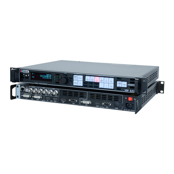
Page 9: Back Panel
BNC – 3G-SDI Loop Out 6. 8 Connect to the SDI input of the next VSP 628PRO or the device with SDI input. DVI-I – DVI Loop Out Connect to the DVI input of the next VSP 628PRO or the device with DVI input. - Page 10 Either a Sender Card or Output option can be installed in this slot. Support sender Card types including Linsn, Nova and Colorlight (sold separately). Refer to Product Sender Cards A range of output options are available for user fitting. Refer to Product Output Options VSP 628PRO User Manual...
-
Page 11: Front Panel
Additionally this button reused for DSK shortkey if enable the DSK function. Optional Signal Buttons If optional input module is fitted, then these two buttons operate as per Dedicated Signal Buttons above. Additionally these buttons are used for direct numeric entry for numbers 7/8. VSP 628PRO User Manual... - Page 12 This button used for dimmer and effects adjusting, also for CHA and CHB selection. Additionally this button is used for direct numeric entry for number 0. TAKE Button This button used for seamless effect switching. Additionally this button reused for load function except in switcher mode. VSP 628PRO User Manual...
-
Page 13: Dimension
Chapter 1: Your Product 1.2.3 Dimension Following is the dimension of VSP 628PRO for your reference: VSP 628PRO User Manual... -
Page 14: Chapter 2 Installing Your Product
Turn the power switch on the rear of the product to the ON position. OLED display will show as below, completing initialization before loading last settings and input/output configuration. On delivery, DVI1 will be the default input signal at 1920x1080@60Hz, and the output format is defaulted to 1920×1080p@60Hz. VSP 628PRO User Manual... - Page 15 Chapter 2: Installing Your Product Program Loading Please Wait RGBLINK VSP628PRO Version 2.79 Initializing... VSP 628PRO User Manual...
-
Page 16: Chapter 3 Using Your Product
Push the [MENU] button to enter the menu display. Turn the rotary knob to navigate to the menu item required. The symbol shows the current item. Push the knob to select and enter into the menu item. As shown in the figure below: VSP 628PRO User Manual... -
Page 17: Understanding The Menu Structure
Chapter 3: Using Your Product 3.2 Understanding the MENU Structure The MENU structure is shown in the figure below: VSP 628PRO User Manual... -
Page 18: Using The Menu
Chapter 3: Using Your Product 3.3 Using the Menu Use the menu system for convenient and intuitive operation. VSP 628PRO OLED display shows the menu items. The OLED display will show the default state when the menu is not in use, or the operation has timed out. Using the MENU button and rotary knob in the front panel, the OLED display will show the corresponding menus according to user selections. -
Page 19: Understanding The Main Menu
There are 11 menu items in the main menu, and display in 3 pages. Turn the rotary knob, and select any menu above, push the rotary knob to confirm, the OLED display will show the submenu. If push the MENU button, the OLED display will return to the last level menu. VSP 628PRO User Manual... -
Page 20: Input Menu
16:9, 5:4, 4:3, 3:2 or 1:1 can be selected. Reset Mask Reset mask if image quality distorts by improper operation. VGA Input VGA input or YPbPr input can be selected. VGA Adjust Brightness red, brightness green, brightness blue, saturation, VSP 628PRO User Manual... -
Page 21: Output Menu
Enable or disable the USB upgrade function. HDMI Point To Point or DP Point To Point can be selected. The resolution that output to VSP 628PRO from 4K2K board will be the same with the HDMI input resolution of 4K2K board if choose HDMI 4K2K Board Point To Point. - Page 22 Output driver setting, the adjustment range is 0~5. Select “ON” or “OFF” Delay Time Short or long can be selected. De_interlacing Enable 2:2PD Select “ON” or “OFF” to enable or disable 2:2PD function. 2:2PD Time The adjustment range is 0~15. VSP 628PRO User Manual...
- Page 23 Select “ON” or “OFF” to enable or disable Flip H function. Flip 90 Degree Select “ON” or “OFF” to enable or disable Flip 90 Degree function. Histogram Select “ON” or “OFF”. Source Freerun, external or input can be selected. Genlock External State VSP 628PRO User Manual...
-
Page 24: Custom Formats Menu
Provide 22 positions for saving parameters. Delete Delete the file. Delay Recall Delay recall time setting. 3.3.7 Transition Menu ->Trans With Fade Trans Time 0.1S Trans With Fade or cut can be selected. Trans Time The adjustment range is 0.1~10S. VSP 628PRO User Manual... -
Page 25: System Menu
Red Min, Red Max, Green Min, Green Max, Blue Min and Blue Max setting, the adjustment range is 0~255. Select “ON” or “OFF”. VFD Bright Lock Front Panel Select “Lock” or “Unlock” the front panel. Timer Timed task setting. Language/语言 Chinese or English can be selected. VSP 628PRO User Manual... -
Page 26: Logo Menu
16*16 GRID, 32*32 GRID, BURST GREYS 50% GRAY, GRAY STEP1, GRAY STEP2, WHITE, BLACK Raster Box Select “ON” or “OFF”. If raster box is “ON”, the border is shown around the image, which is for testing. VSP 628PRO User Manual... -
Page 27: Tech Support Menu
Input SDI1, Input SDI2, Multi Sync, 2U LCD and Sender Card. Serial Number Displays the serial number of the device. Email Provides on display contact information for RGBlink Support by Email. Website Provides on display contact information for RGBlink website. 3.3.13 Factory Reset Menu ->Factory Reset... -
Page 28: System Operation Mode
3.4.2 Set the System Operation Mode Go to the SYSTEM menu select the required SYSTEM MODE. For all SYSTEM MODES other the SPLIT, the VSP 628PRO will show “SYSTEM MODE SETTING...”, which will take up to 30secs before the device is ready. -
Page 29: Pip Setting
Push the [PIP] button, the button light is on, and enable the PIP function. Select the signal in PIP VSP 628PRO can output two same or different signals to the output, the settings are as follows: 1. Push the [PIP] button, and enable the PIP function. - Page 30 Project: There is one LED display, the size is 3864x1152, divide into right and left halves, the left width is 1824 and the right width is 2040, we will cascade the two LED displays with one VSP 628PRO, and display a complete picture in the whole screen. (1) Connect the interface Connect the DVI signal to the DVI input interface, connect the DVI output to the left LED sending card, and connect the HDMI output to the right LED sending card.
- Page 31 >> Views >> Push the rotary knob to confirm. Turn the knob to select <Output Format>, and set the output formats as 2048x1152@60Hz. Channel Select ->Output Format >> CVBS Format >> Out Auto Config (N/A) >> VSP 628PRO User Manual...
- Page 32 ->Save >> Delete >> Delay Recall >> Push the rotary knob to confirm. Turn the rotary knob to select the save mode, for example, select File 4, push the rotary knob to confirm. Save ->File 4 VSP 628PRO User Manual...
-
Page 33: Set The Output Resolution
Formats>, push the rotary knob and confirm. Custom Formats ->1920×1080×60.0 Use red number keys and knob for enter 1. Enter digits of desired resolution by pushing the red number buttons. For example, input 1536 as following: VSP 628PRO User Manual... - Page 34 ->1536×1536×60.0 Use red number keys and knob for enter 4. After input all the values, push the rotary knob to enable VSP 628PRO to output this resolution. VSP 628PRO will take 5~10 seconds to enable this output resolution. VSP 628PRO...
-
Page 35: Set The Led Display Connection
Chapter 3: Using Your Product 3.6 Set the LED Display Connection VSP 628PRO can realize two connection as follows connecting the Port D or Port U of one sending card to LED screen and connecting the both Port D and Port U of one sending card to LED screen (PORT A or PORT B is for Colorlight, and PORT D or PORT U is for Linsn). - Page 36 (8) Set the horizontal card, vertical card, width and height. For example, set horizontal card as 3, vertical card as 2, width and height as 120, shown as follows: Choose Cable Port U ->Horizontal Card Vertical Card Width ->Height Port Offset X Port Offset Y >> Connect Type VSP 628PRO User Manual...
- Page 37 Chapter 3: Using Your Product After setting, turn the rotary knob and select <Connect Type> according to actual connection mode. VSP 628PRO support 8 kinds of connection modes, they are respectively. Height Port Offset X Port Offset Y ->Connect Type >>...
- Page 38 Push the rotary knob to confirm, turn the rotary knob, select <Card Type> in <Quick Connection> option, push the rotary knob to confirm, turn the rotary knob, select the sending card type, for example, select Linsn (VSP 628PRO supports Linsn and Colorlight sender card, for Nova sender card, it only support brightness and Gamma adjustment).
- Page 39 ->Connect Type >> Select the connection mode, the setting is same with Port U. Then connection of both the Port D and Port U of One Sending Card to LED Screen is finished. Rendering is as follows: VSP 628PRO User Manual...
-
Page 40: Capture Logo
4. Push the rotary knob to confirm. Turn the rotary knob again, select <Capture Logo>, and set “Capture Logo” as “Enable”: ->Capture Logo Enable Logo Present Logo 1 Capture logo will finished after a few seconds. VSP 628PRO User Manual... -
Page 41: Using Logo Button
AOI Raster Box: If Raster Box (above) is “ON”, size settings in this menu for Box X, Box Y, Box Width and Box Height are displayed. Select Reset to restore default settings. AOI raster box will display for all signals except LOGO (Test Pattern). VSP 628PRO User Manual... -
Page 42: Saving Views
Chapter 3 : Using Your Product 3.9 Saving Views VSP 628PRO provides 22 positions for saving or recording parameters. To save current parameters and settings: 1. Push the [MENU] button to enter to the menu items, turn the rotary knob, select <Views>, push the rotary knob to confirm. -
Page 43: Recall Saved Settings
Chapter 3: Using Your Product 3.10 Recall Saved Settings VSP 628PRO provides 22 positions for saving or recording parameters. To recall saved settings: 1. Push the [MENU] button to enter to the menu items, turn the rotary knob, select <Views>, push the rotary knob to confirm. -
Page 44: Chapter 4 Controlling Your Processor Remotely
4.1 Using the Windows Control Program Install the software on a Windows computer, launch the application. 4.1.1 Set up Communication First, connect the VSP 628PRO to the computer with the network cable or USB cable, and boot the device. Then, click the connection icon... -
Page 45: Use
Click “Set” after finish. Mode Click “Mode”, and enter to the interface as below. VSP 628PRO supports Std mode, PIP Mode, Dual 2K Mode, Switcher Mode and Split Mode. User should select Std Mode before choose PIP Mode, or it will not be shown on the interface. - Page 46 Select the output formats of CHA and CHB by selecting from scrolling down list if choose Dual 2K Mode. Screen Parameter Select the ratio mode of Screen Param A by selecting from scrolling down list, including Full, Same with Input, 3:2, 4:3, 5:4 and 16:9. VSP 628PRO User Manual...
- Page 47 Bits: Set the image bits, system default HDMI is 10 bits, user can select 8 bits or 12 bits. Genlock Use can enable or disable the genlock function, and set external and input signal genlock. Input Click “Input”, and enter to the interface as below: Input Format VSP 628PRO User Manual...
- Page 48 Click “Layer”, and enter to the interface as below: Display Mode Select the display mode as live or freeze. Mirror Select H Mirror or V Mirror. Set the hue of the image according to actual need, the adjustment range is -180~180. VSP 628PRO User Manual...
- Page 49 Noise Reduction. The adjustment range is 0~3. Gamma Enable the gamma function and set the gamma value by selecting from scrolling down list. Chroma Set the chroma of the image according to actual need. The adjustment range is 0~399. VSP 628PRO User Manual...
- Page 50 All the settings above are only for the selected channel, and for preview channel in switcher mode. Save Click “Save”, and enter to the interface as below. VSP 628PRO supports 22 positions to save the parameters. Click the save mode according to actual need. Load Click “Load”, and enter to the interface as below.
- Page 51 Chapter 4: Controlling Your Processor Remotely Other : Read the current parameters of VSP 628PRO. : Reset the factory settings. : Upgrade the device, and user can clear the log. : Save the data to the computer hard drive. VSP 628PRO...
- Page 52 Chapter 4: Controlling Your Processor Remotely : Load the data from the computer. : Show the device version information. VSP 628PRO User Manual...
- Page 53 : This software supports both Chinese and English, user can switch the language by “Language” option. : Operation permissions settings for manager, log in and set the log password of windows control program. VSP 628PRO V2.0 can not support this function. VSP 628PRO User Manual...
-
Page 54: Using The Vsp 628Pro App For Android & Ios
(For more details about setting, please refer to router’s instruction). 2. Connect the LAN port of router to the LAN port of VSP 628PRO with the network cable. 3. Connect to the router by IOS or Android device, system default IP automatic access, use the web browser to access “192.168.0.100”, the default IP address of VSP 628PRO,... - Page 55 3) After connection, it enters to the processor manager interface, as follows: 4) Click <Signal Select>, it supports 4 different modes, as follows: 5) Click <Save And Load>, it supports 22 kinds of save modes, as follows: VSP 628PRO User Manual...
- Page 56 6) Click <Image Setting>, user can adjust the parameters in preview mode, as follows: 7) Click <Mask And Scale>, user can mask and scale the image, as follows: 8) Click <Test Pattern>, there are 13 kinds of test patterns, as follows: VSP 628PRO User Manual...
- Page 57 9) Click <Parameter Setting>, user can adjust the output resolution, as follows: 10) Click <Information>, user can view the device mode, serial number, IP address and module versions. User can also click “Factory Reset” to reset to its factory settings. VSP 628PRO User Manual...
-
Page 58: Connecting To An Ethernet Network
VPN router model: Netcore 255 or 266; Volans VE 760W or 982W). One VSP 628PRO processor (as long as the router’s network ports can connect to, user can place multi pieces of VSP 628PRO). - Page 59 Go to router setting part and find out “LAN port setting”, change the default value “192.168.1.1” to be “192.168.0.1”. Save the setting and restart the router, then user can control on VSP 628PRO via windows control software. VSP 628PRO...
-
Page 60: Using A Vsp 628Pro With Web Option
First, the formation of LAN Remote Control Platform: one Ipad or one Iphone, one router (with wireless functions, for example with a wireless-enabled VPN router models: Netcore 255 and 266. Volans VE760W, 982W.), one VSP 628PRO processor (can be more processors, as long as the network interface can be connected to the router) - Page 61 Chapter 4: Controlling Your Processor Remotely After connection successfully, Web page appears as VSP 628PRO system control interface. Click on the toolbar below the control interface, then accesses setup menu, now WEB control on VSP 628PRO is available. VSP 628PRO...
-
Page 62: Chapter 5 Ordering Codes
Chapter 5 Ordering Codes 5.1 Product 100-0628-03-0 VSP 628PRO 100-0628-04-0 VSP 628PRO-WEB 5.2 Options 5.2.1 Input Options 190-0628-01-0 Dual CVBS/Composite Input Module 2 × CVBS 190-0628-02-0 Dual USB Input Module 2 × USB 190-0628-03-0 Dual VGA Input Module 2 × VGA... -
Page 63: Accessories
Chapter 5: Ordering Codes 5.2.3 Accessories RCRCPJ00011 DVI to VGA adapter 5.3 Sender Cards RCRCPJ00090 Linsn TS801 RCRCPJ00091 Linsn TS802 RCRCPJ00110 Nova MSD300 RCRCPJ00112 Nova MSD600 RCRCFJ00133 Colorlight iT7 VSP 628PRO User Manual... -
Page 64: Chapter 6 Support
[MENU] button, then choose <OUTPUT>, turn the knob and choose <Color Space/Sample/Bit>, choose the HDMI output format as DVI. 6.1.3 Flash Point on LED Display when Output Frequently Flash Point on LED Display when Output Asked Question VSP 628PRO User Manual... -
Page 65: Android Or Ios App Cannot Connect
IP, the IP will conflict if consistent, and unable to search the device and normal connection. Please change the device IP address, and make sure it is in the same network segment. VSP 628PRO User Manual... -
Page 66: Vga Input Offset Or Cannot Be Full Size Shown
Show Blurred Screen when Rotate for I System Input Asked Question Change the Input as P System Troubleshooting VSP 628PRO can not currently support the I system input rotate, please change the input as P system. 6.1.7 Can’t Do Split for I System Input Frequently Can’t Do Split for I System Input... -
Page 67: Show Upgrade Error After Upgrade Mcu Program
Asked Question Upgrade the Program Again VSP 628PRO only needs to upgrade the package after upgrade the program, and only for some old version devices need to upgrade the MCU program. Once upgrade the MCU program, the OLED panel will Troubleshooting show writing tip during upgrading. -
Page 68: Contact Us
Chapter 6: Support 6.2 Contact Us VSP 628PRO User Manual... -
Page 69: Chapter 7 Appendix
300mV Sync-tip: 0V Supported Resolution VGA-UXGA (800×600@60 I 1024×768@60 I 1280×1024@60 I 1440×900@60 I 1600×1200@60) DVI Input (Standard) Number of Inputs Connector Standard DVI-D socket Supported Resolution SMPTE: 625/25/50 PAL, 525/29.97/59.94 NTSC, 1080P50/59.94/60 I 1080i50/59.94/60, 720p50/59.94/60 VSP 628PRO User Manual... - Page 70 1920×1080I/50 (2:1) or 1920×1080/25 (PsF) I 1920×1080/30 (1:1) I 1920×1080/25 (1:1) I 1920×1080/24 (1:1) I 1920×1080/24 (PsF) SMPTE 125M (SD):1440×487/60 (2:1) SMPTE ITU-R BT.656 (SD):1440×576/50 (2:1) Or dual link progressive, 625-line generic. Balance Belden 1694A cable: VSP 628PRO User Manual...
- Page 71 1280×720@60 I 1280×768@60 I 1280×800@60 I 1280×1024@60 I 1360×768@60 I 1366×768@60 I 1400×1050@60 I 1440×900@60 I 1600×1200@60 I 1680×1050@60 I 1920×1080@60 I 1920×1200@60 I 2048×1152@60 I 2560×816@60 Format Standard HDMI 1.3 VGA Output (Standard) Number of Outputs Connector Standard DB15 Socket VSP 628PRO User Manual...
- Page 72 Supported Resolution VGA-UXGA (800×600@60 I 1024×768@60 I 1280×1024@60 I 1440×900@60 I 1600×1200@60) DVI Input (DVI Optional Module) Interface Appearance Board Size 93.8(L)×17(W)(mm) Number of Inputs Connector Standard DVI-D socket Supported Resolution SMPTE: 625/25/50 PAL, 525/29.97/59.94 NTSC, VSP 628PRO User Manual...
- Page 73 SMPTE 274M (HD) : 1920×1080I/60 (2:1) or 1920×1080/30 (PsF) I Supported Resolution 1920×1080I/50 (2:1) or 1920×1080/25 (PsF) I 1920×1080/30 (1:1) I 1920×1080/25 (1:1) I 1920×1080/24 (1:1) I 1920×1080/24 (PsF) SMPTE 125M (SD):1440×487/60 (2:1) SMPTE ITU-R BT.656 (SD):1440×576/50 (2:1) Or dual link progressive, 625-line generic. VSP 628PRO User Manual...
- Page 74 1Vpp±3db (0.7V Video+0.3v Sync ) 75 ohm Multiplex 480i, 576i HDMI_DP_4K2K_IN Optional Module Interface Appearance Board Size 93.8(L)×17(W)(mm) DP Input Number of Inputs Connector DisplayPort Supported Resolution VESA: 3840×2160×24 I 3840×2160×25 I 3840×2160×30 SMPTE: 625/25/50 PAL, 525/29.97/59.94 NTSC, 1080P50/59.94/60 I 1080i50/59.94/60, VSP 628PRO User Manual...
- Page 75 1920×1080/25 (1:1) I 1920×1080/24 (1:1) I 1920×1080/24 (PsF) SMPTE 125M (SD):1440×487/60 (2:1) SMPTE ITU-R BT.656 (SD):1440×576/50 (2:1) Or dual link progressive, 625-line generic. Equalization Belden 1694A 100m HD 1.485G, 300m SD 270Mbps SFP Fiber Output Number of outputs Connector LC interface VSP 628PRO User Manual...
- Page 76 1920×1080/25 (1:1) I 1920×1080/24 (1:1) I 1920×1080/24 (PsF) SMPTE 125M (SD):1440×487/60 (2:1) SMPTE ITU-R BT.656 (SD):1440×576/50 (2:1) Or dual link progressive, 625-line generic. Equalization Belden 1694A 100m HD 1.485G, 300m SD 270Mbps CVBS Output (OC Optional Module) VSP 628PRO User Manual...
- Page 77 Transition effects Fade in and fade out switching between any two inputs Extras Communication USB TCP/IP Power Supply 85-264V IEC-3 Working Environment 0°C~45°C Stored Environment 10% to 90% Product Warranty 3 years parts and labor warranty VSP 628PRO User Manual...
-
Page 78: Software Upgrade
Chapter 7: Appendix 7.2 Software Upgrade Windows Control Program Upgrade Guideline 1. Connect VSP 628PRO to PC via USB cable. 2. Download the windows control program (Please click the link http://www.rgblink.cn/en/products_detail.aspx?id=261 to the VSP 628PRO home page, and click the “Download” option to get the windows control program). - Page 79 , and check the version information (If the Control Board SW version is 2.13 or lower, it needs to upgrade VSP628PRO_EDID_XX.bin) 8. Click the button , and choose the upgrade path, get the update file: VSP 628PRO_Packge_Bata_xx.bin ready. Like below: VSP 628PRO User Manual...
- Page 80 9. Click start icon to upgrade. 10. It takes 2~3 minutes to finish update. And a message “Down Load Success” will pop out if finish. 11. Please re-power the VSP 628PRO after finished update. (Automatically factory reset when re-opening.) VSP 628PRO User Manual...
-
Page 81: Installing Options
Chapter 7: Appendix 7.3 Installing Options VSP 628PRO is based on module based structure, user can install or replace the optional module according to actual need. The installation steps are as follows: Install the Optional Module 1. Disconnect the power and all the signal and control cables. - Page 82 Chapter 7: Appendix (Figure 2) 4. Push the input module into the input module slot, and fix it with 2 fixed screws (Figure VSP 628PRO User Manual...
- Page 83 5. Embed the input module block in the input module slot, and fix it with 2 fixed screws (Figure 4): (Figure 4) 6. Assemble the top panel, and fix it with 5 fixed screws that removed in step 2, then optional module installation is finished (Figure 5): VSP 628PRO User Manual...
- Page 84 Chapter 7: Appendix (Figure 5) Note: Above instructions are only for input optional module. For VSP 628PRO, if user would install the output optional module, first, take apart the top panel, and unscrew the 3 fixed screws on sending card board to remove it (Figure 6).
- Page 85 The install steps for optional module replacement are the same as above, but the following need to note: 1. Take apart the top panel, and unscrew the 2 fixed screws on input optional module to remove it (Figure 9). VSP 628PRO User Manual...
- Page 86 3. Push the input module into the input module slot, the install steps are the same as step 4 to step 6 in “Install the Optional Module” part. Note: The install steps for output optional module replacement are the same as above. VSP 628PRO User Manual...
-
Page 87: Terms & Definitions
“Color burst”: In color TV systems, a burst of subcarrier frequency located on the back porch of the composite video signal. This serves as a color synchronizing signal to establish a frequency and phase reference for the chroma signal. Color VSP 628PRO User Manual... - Page 88 1.485 Gbit/second. Multiple video resolutions exists including progressive 1280x720 and interlaced 1920x1080 resolution. Up to 32 audio signals are carried in the ancillary data. “JPEG” (Joint photographic Expects Group): Commonly used method of lossy VSP 628PRO User Manual...
- Page 89 The standard specifies component connection standards with regard to the computer interface. It is also called RS-232-C, which is the third version of the RS-232 standard, and is functionally identical to the CCITT V.24 standard. VSP 628PRO User Manual...
- Page 90 USB continues to grow, from keyboards, mice, and printers to scanners, digital cameras, and ZIP drives. “VESA”: Video Electronics Standards Association. A nonprofit number organization dedicated to facilitating and promoting personal computer graphics through VSP 628PRO User Manual...
- Page 91 4. It has a pixel by line resolution of 640×480 with a color palette of 16 bits and 256,000 colors. “YCrCb”: Used to describe the color space for interlaced component video. “YPbPr”: Used to describe the color space for progressive-scan (non-interlaced) component video. VSP 628PRO User Manual...
-
Page 92: Revision History
2. Update the dimension drawing. 3. Update the menu tree. 4. Add “How to Realize LED Screen Connection”. 5. Update the fax number. 6. Update the company logo. V1.9 2016-04-20 0009# Update the style and structure. Vira VSP 628PRO User Manual... - Page 93 Chapter 7: Appendix V2.0 2016-08-02 0010# 1. Update the cover picture. Vira 2. Update the menu tree. 3. Update the specification. V2.1 2018-11-02 0011# 1.Update default mode Many VSP 628PRO User Manual...
Need help?
Do you have a question about the VSP 628PRO and is the answer not in the manual?
Questions and answers