
Related Manuals for RGBlink VSP 1314


Summary of Contents for RGBlink VSP 1314
-
Page 1: User Manual
VSP 1314 User Manual Manual #:RGB-RD-UM-V1314 E001 Revision:V1.1 – VSP 1314 User Manual... - Page 2 RGBLINK. Notice RGBlink provides this manual “as is” without warranty of any kind, either expressed or implied, including but not limited to the implied warranties or merchantability and fitness for a particular purpose. RGBlink may make improvements and/or changes to the product(s) and/or the program(s) described in this publication at any time without notice.
- Page 3 RGBlink. If the purchaser or a third party carries out modifications or repairs on goods delivered by RGBlink, or if the goods are handled...
- Page 4 Company address RGBlink Science & Technology Co., Ltd. Headquarter: S603 Weiye Building Torch Hi-Tech Industrial Development Zone Xiamen, Fujian Province, P.R.C Shenzhen office: Building 3, A Baiwang Plaza, Xili Nanshan District Shenzhen, Guangdong Province, P.R.C Beijing office:Room 602, Building 7, Caimanjie,No.69 Chaoyang District,Beijing China Shanghai office:Alley 1358 Building 3 Tongpu Road,Shanghai,P.R.C...
- Page 5 To avoid fire hazard, use only the fuse having identical type, voltage rating, and current rating characteristics. Refer fuse replacement to qualified service personnel. Do Not Operate in Explosive Atmospheres To avoid explosion, do not operate this product in an explosive atmosphere. VSP 1314 User Manual...
- Page 6 Highlights an essential operating procedure,condition or statement. CAUTION The exclamation point within an equilateral triangle is intended to alert the user to the presence of important operating and maintenance (servicing) instructions in the literature accompanying the appliance. VSP 1314 User Manual...
- Page 7 Change History The table below lists the changes to the Video Processor User Manual. Format Time ECO# Description Principal V1.0 2012-10-12 0000 Release V1.1 2013-01-07 0001 Buttom modify: Change Change VSP 1314 User Manual...
-
Page 8: Table Of Contents
System Overview ................20 Application Questions ..............21 Hardware Orientation ............22 In This Chapter ................. 22 VSP 1314 Rear Panel ..............23 INPUT Interface ..................23 1:USB Input .................... 23 2~5:CVBS Input ..................24 6.7: VGA Input ..................24 17.18.19:DVI Input ................ - Page 9 20:DVI Output ..................25 21:DVI +VGA-DVI Output ..............25 Switch and Power ..................26 27.28:Power Interface and Switch ............. 26 VSP 1314 Front Panel ..............27 LCD panel ....................28 Menu Buttons ................... 28 Hardware Installation ............34 In This Chapter ................. 34 Safety Precautions ................
- Page 10 How to adjust output resolution ............50 How to adjust size and position of image ........51 How to scale image ................53 How to switch signal of single image ..........55 How to set picture in picture ............56 VSP 1314 User Manual...
- Page 11 How to save parameter ..............67 How to load parameter ..............68 A.Specification ................69 B.Contact Information ..............71 C.Firmware Upgrade..............72 Function Firmware Upgrade ............72 Image Firmware Upgrade..............74 Communication Firemware Upgrade ..........75 VSP 1314 User Manual...
-
Page 12: Introduction
Introduction This chapter is designed to introduce you to the VSP 1314 User Manual. Areas to be covered are: Chapter Structure How to use this manual Tems and Definitions System Overview Application Questions VSP 1314... -
Page 13: Chapter Structure
The following chapters provide instructions for all aspects of VSP1314 operations. Chapter 1 Introduction Chapter 2 Hardware Orientation Chapter 3 Hardware Installation Chapter 4 Menu Orientation Chapter 5 System Setup and Opetations Appendix A Specification AppendixB Contact information AppendixC Firmware Upgrade VSP 1314 User Manual... -
Page 14: How To Use This Manual
“Communication Software Control Guide” on page 45. Should you have any questions regarding the installation or operation of VSP 1314, please consult with the factory. Refer to Appendix C, ― Upgrading Software on page 72 for contact information. VSP 1314... -
Page 15: Terms And Definitions
“Color bars”: A standard test pattern of several basic colors (white, yellow, cyan, green, magenta, red, blue, and black) as a reference for system alignment and testing. In NTSC video, the most commonly used color bars are the SMPTE standard color bars. In PAL video, the VSP 1314 User Manual... - Page 16 “Gamma”: The light output of a CRT is not linear with respect to the voltage input. The difference between what you should have and what is actually output is known as gamma. “HDMI” - High – Definition Multimedia Interface: An interface used VSP 1314 User Manual...
- Page 17 VCR, or computer. Other forms of PIP displays include Picture-by-Picture (PBP) and Picture-with-Picture (PWP), which are commonly used with 16:9 aspect display devices. PBP and PWP image formats require a separate scaler for each video window. VSP 1314 User Manual...
- Page 18 “Sync”: Synchronization. In video, sync is a means of controlling the timing of an event with respect to other events. This is accomplished with timing pulses to insure that each step in a process occurs at the VSP 1314 User Manual...
- Page 19 640×480 with a color palette of 16 bits and 256,000 colors. “YCrCb”: Used to describe the color space for interlaced component video. “YPbPr”: Used to describe the color space for progressive-scan (non-interlaced) component video. VSP 1314 User Manual...
-
Page 20: System Overview
1.Introduction System Overview System Overview The VSP 1314 is a 3 layers seamless switcher and scale that accepts a wide variety of video signals,including RGB computer-video, HDTV, which support 4 composite (CVBS),2 VGA, 2 DVI (compatible with HDMI1.3),2 USB inputs and 2 DVI3(background window). It combines truly seamless, glitch-free switching with advanced scaling technology to meet the requirement of high quality,high resolution video presentation.Use the... -
Page 21: Application Questions
1.Introduction Application Questions Application Questions RGBlink offers solutions to demanding technical problems. Any application questions, or required further information, please contact with our Customer Support Engineers. Refer to Appendix B for contact details. VSP 1314 User Manual... -
Page 22: Hardware Orientation
Hardware Orientation In This Chapter This chapter provides detailed information about the VSP 1314 hardware. The following topics are discussed: VSP 1314 Rear Panel VSP 1314 Front Panel VSP 1314 User Manual... -
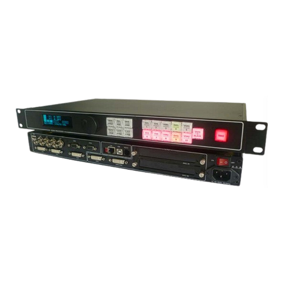
Page 23: Vsp 1314 Rear Panel
2.Hardware Orientation VSP 1314 Rear Panel VSP 1314 Rear Panel This chapter provides detailed information about the VSP 1314 hardware. The following topics are discussed: INTERFACE INTERFACE USB Input 12.13.21.23 Gigabit copper port CVBS Input 14.24 Power supply port of Sending card 6. -
Page 24: 2~5:Cvbs Input
2.Hardware Orientation VSP 1314 Rear Panel 2~5:CVBS Input CVBS 1/2/3/4 input. Can receive standard video signal from players, cameras etc. Input supported resolution 480i and 576i via BNC. Supported standards include: PAL, NTSC and SECAM. 6.7: VGA Input VGA 6/7 Input Interface, input the video signal from HD player and Computer, etc. -
Page 25: Rs232 Interface
2.Hardware Orientation VSP 1314 Rear Panel 11.RS232 Interface Used to connect the computer. OUTPUT Interface 12.13.22.23: Gigabit copper port Gigabit copper port, connect to LED screen. 14.24:Power supply port of Sending Card Power has been already supplied by video processor itself, don’t need external power supply. -
Page 26: Switch And Power
2.Hardware Orientation VSP 1314 Rear Panel Switch and Power 27.28:Power Interface and Switch AC 90-264V 3.8A 50/60Hz IEC-3 Power Interface VSP 1314 User Manual... -
Page 27: Vsp 1314 Front Panel
Insert power cord and push power to ON position. LCD module on the front panel will show RGBLINK and go into self verification before it load last setting config and send processed image to the target monitor. For the first setup, DVI input is default source. -
Page 28: Lcd Panel
2.Hardware Orientation VSP 1314 Front Panel VSP 1314 front panel as following: LCD panel Used to show the key and communication interactive menu. Menu Buttons Color operation panel: Green light means on work; Red light means optional choice for work;... - Page 29 2.Hardware Orientation VSP 1314 Front Panel Detail please refer to How to select switching effect. PIP mode multiplexing button; Press button and light up red,that means is1/2 mode;layer 1 above layer2; Press button and light up red,that means is 2/1 mode;layer 2 above layer1;...
- Page 30 2.Hardware Orientation VSP 1314 Front Panel Detail please refer to How to save parameter. Press button and light up green to enter to LOAD mode,at the same time CV1/1, CV2/2, USB1/3, DVI1/4, VGA1/5, CV3/6, CV4/7, USB2/8, DVI2/9, VGA 2/10 all of them light up green ,the figure of 1,2,3,...
- Page 31 2.Hardware Orientation VSP 1314 Front Panel Three key combination use as following: SCALE: Press SCALE/CROP,light up green to enter to Scale setting;At the same time H SIZE\H POS light up green,rotate the adjust knob can adjust the hight of picture;Press H SIZE\H POS ,light up red to enter to light-vertical position setting,rotate the adjust knob can adjust the position of veitical;Press V SIZE/V POS ,light up green to enter to Width setting,rotate...
- Page 32 2.Hardware Orientation VSP 1314 Front Panel Note The percentage of CROP is the curren output resolution percentage,after scale set full screen.Such as resolution is: 1024x768,set width as 50,set transverse position as 0,height as 50,set certical position as 0.That is scale the 1/4 picture of full screen at the top right corner as 1024x768 output。...
- Page 33 2.Hardware Orientation VSP 1314 Front Panel DVI1/4:DVI1signal source and Save 4 and Load 4 muitiplexing button; VGA1/5:VGA1signal source and Save 5 and Load 5 muitiplexing button; CV3/6: CV3 signal source and Save 6 and Load 6 muitiplexing button; CV4/7:CV4 signal source and Save 7 and Load 7 muitiplexing button;...
-
Page 34: Hardware Installation
Hardware Installation In This Chapter This chapter provides comprehensive installation instruction for VSP 1314 hardware: Following is the size of VSP 1314 for your reference. VSP 1314 User Manual... -
Page 35: Safety Precautions
Unpacking and Inspection Before opening VSP 1314 process shipping box, inspect it for damage. If you find any damage, notify the shipping carrier immediately for all claims adjustments. As you open the box, compare its contents against the packing slip. -
Page 36: Menu Orientation
Menu Orientation In This Chapter This chapter describes all VSP 1314 processor menus, including how they are accessed, the functions that are available, and descriptions of each menu tree (in block diagram format). The following topics are discussed: • MENU ... -
Page 37: Menu
,it means is in a selecred state,press knob to make sure and enter to the corresponding menu to set or view. Picture 1: VSP 1314 User Manual... - Page 38 4.Menu Orientation MENU Picture 2: VSP 1314 User Manual...
-
Page 39: Menu
Setup switch;rotate the adjust knob to select ON ,then press the knob to make sure and enter to DE setting,can up or down of menu: DE H Start: Abscissa setting;DE V Start: Ordinate setting; DE Width:Width setting;DE Height:Height setting; VSP 1314 User Manual... - Page 40 User can adjust and set according to actual condition,This function mainly suitable for professional to operate image quality. Nonprofessional don’t recommend to operate obove setting.If image quality were distortion because of improper operation,can reply the factory setting. VSP 1314 User Manual...
-
Page 41: Menu
MENU---Split VSP1314 also can work as seamless splicing unit,use DVI3 to as splicing unit input signal,support horizontally splicing or vertical splicing; Detail please refer to How to splicing with DVI3 VSP 1314 User Manual... -
Page 42: Menu
System information: SN:The serial number of this processor, you can check the product information according this number; MCU VER:Version information of MCU; FPAG VER:Version information of FPGA; IP:Information of IP; Video Firmware VER:Version information of Video Firmware; VSP 1314 User Manual... -
Page 43: Menu
Wipe Curtain Out、Wipe Plus Out;But only Wipe Soft have soft effect; Cut :Cut Left、Cut Right、Cut Down、Cut Up、Cut Square、Cut Curtain、 Cut Center.It also supports the user defined switching speed;Adjustment value range is “0.5 s-30.0 s” Detail please refer to VSP 1314 User Manual... - Page 44 4.Menu Orientation MENU VSP 1314 User Manual...
-
Page 45: System Setup And Operation
How to set input matrix How to set DVI3 as background How to splicing with DVI3 How to use BlACK How to use Test Pattern How to save parameter How to load parameter VSP 1314 User Manual... -
Page 46: How To Connect Equipment
OUTPUT FORMAT. 21. System default DVI2+VGA output interface as preview output,Preview output signal before output via displayer. Output signal is DVI video signal and VGA video signal,can connect display that with DVI or VGA interface to VSP 1314 User Manual... - Page 47 USB ( USB-A Interface ) can connect USB or mobile HDD with USB.Support image format :JPGE,BMP,PNG ;Support video format: MP4, MPEG1, MPEG2, RMVB, MJPG.This interface also used to upgrade 6M48. 27.AEC:The range of power:AC 85-264V 50/60Hz 28.Power switch; VSP 1314 User Manual...
-
Page 48: How To Make Equipment Normal Operation
How to make equipment normal operation 1. Make sure equipment normal operation; 2. After power on equipment starts self state,fan starts,scan button; 3. After scanning,LCD will show as following: AVDSP Series VSP 1314 Seamless Switcher & Scaler System Initializing 100% CH1:DVI1 NO INPUT... -
Page 49: How To Preview Input Signal Source
3. The signal of red light can preview switching,can check image at preview output; 4. System default DVI as Program output,DVI2 and VGA as Preview output; 5. Schematic diagram 1 switch to Schematic diagram 2,just to press TAKE. Schematic diagram 1: Schematic diagram 2: VSP 1314 User Manual... -
Page 50: How To Adjust Output Resolution
3. Press knob to make sure,Enter to OUTPUT to select Output Format; Output Format Output Adjust Screen Aspect Ratio 4. Press knob to make sure,Enter to Output Format;Press knob to select sresolution,then press to make sure; Output Format <1024x768 60Hz> Press<OK>Select Format VSP 1314 User Manual... -
Page 51: How To Adjust Size And Position Of Image
DVI2 Scale HSize <1024> Scale HPos < 0> Scale VSize < 768> Scale VPos < 0> 3. Press H SIZE\H POS,light up red light-transverse position setting,rotate the adjust knob,can adjust the position of transverse; VSP 1314 User Manual... - Page 52 0> 5. Press V SIZE/V POS,light up red light-vertical position setting,rotate the adjust knob can adjust the position of vertical; DVI2 Scale HSize <1024> Scale HPos < 0> Scale VSize < 768> Scale VPos < 0> VSP 1314 User Manual...
-
Page 53: How To Scale Image
DVI2 Crop HSize < 100> Crop HPos < 50> Crop VSize < 100> Crop VPos < 50> 3. Press H SIZE\H POS ,light up red light-transverse position setting,rotate the adjust knob can adjust position of TRANSVERSE; VSP 1314 User Manual... - Page 54 5. Press V SIZE/V POS ,light up red light-vertical position setting,rotate the adjust knob can adjust the position of vertical; DVI2 Crop HSize < 100> Crop HPos < 50> Crop VSize < 100> Crop VPos < 50> VSP 1314 User Manual...
-
Page 55: How To Switch Signal Of Single Image
TAKE to switch the selected signal to Program output. Operation as following: Operation schematic diagram1: Operation schematic diagram2: VSP 1314 support display 3 layers : Layer 1 including:CV1,CV2,USB1,DVI1,VGA1 , Layer 2 including:CV3,CV4,USB2,DVI2,VGA2 , Layer 3 is background input,user can set DVI3 as background signal or as test pattern. -
Page 56: How To Set Picture In Picture
3. Set DVI2 as Preview output,scale to:384x384,and adjust position to: X-288,Y-144; 4. Press ,and button light up red ; 5. PIP mode 1:Press and light up red as following: 6. PIP mode 2:Press and light up red,as following: VSP 1314 User Manual... -
Page 57: How To Select Switching Effect
Fade in Fade out、Wipe soft、Wipe hard; Effects *Effectsn Mode:<CUT> Effects *Effectsn Mode:<FADE> Display Time:<1.5S> Effects *Effectsn Mode:<WIPE Hard> Wipe Mode: < Wipe Left> Wipe Speed: <8 S> Effects *Effectsn Mode:<WIPE SOFT> Wipe Mode: < Wipe Left> Wipe Speed: <8 S> VSP 1314 User Manual... - Page 58 5.System Setup and Operation How to select switching effect 3. Press the adjust knob to ensure after selecting,then to set switch speed and mode,press the adjust knob to ensure; VSP 1314 User Manual...
-
Page 59: How To Set Input Matrix
4.and enter to set Input Matrix; Channel 1: Input 1 Channel 2: Input 2 Channel 3: Test Pattern 5.Press the adjust knob to ensure and enter Matrix;Rotate the adjust knob to set these 3 Channel,That can achieve matrix; VSP 1314 User Manual... -
Page 60: How To Set Dvi3 As Background
3 and press to ensure.If DVI3 signal is effective and the output resolution is the same with equipment,LCD will show input success if not will show Error infomation! Channel 1: Input 1 Channel 2: Input 2 Channel 3: Test Pattern VSP 1314 User Manual... - Page 61 5.System Setup and Operation How to set DVI3 as background 5.Please make sure that input and output formats are consistent ,if show Input Error; DVI 3 Input Error! Please Make Sure That Input And Output Formats are Consistent! VSP 1314 User Manual...
-
Page 62: How To Splicing With Dvi3
Through Split Output Channel: DVI1 Display Width: 1024 5. Press the adjust knob then rotate it to select Split Mode.Press the adjust knob then rotate it to select Split Mode.There are three kinds of split mode:Through、H1/2、V1/2; VSP 1314 User Manual... - Page 63 7. Repeat the above operation step,can adjust the display range of DVI3 input source.That is scale a part image of DVI3 and display on output port. Display Height: Display Local X: Display Local Y: Screen Width: 1024 VSP 1314 User Manual...
- Page 64 Config Update (Push OK) 9.Parameter correction,If splicing is stagger or there is a flower on screen,because of DVI3 input interrupt or unstable,can correct the parameter. Screen Height: Screen Local X: Screen Local Y: Config Update (Push OK) VSP 1314 User Manual...
-
Page 65: How To Use Black
5.Press the adjust knob and enter it,select Manua Color; Manual Color Auto Color Roll Right Roll Left 6.Press the adjust knob and enter it;Press the adjust knob to set Red、 Green、Blue as 0,That is set test pattern as background; Red: Green: Blue: VSP 1314 User Manual... -
Page 66: How To Use Test Pattern
Auto Color Roll Right Roll Left Roll Up Roll Down Roll Up Left Roll Down Right Color BAR H Color BAR V Gray BAR H Gray BAR V 3.User can select mode arbitrarily then press to ensure; VSP 1314 User Manual... -
Page 67: How To Save Parameter
There are 10 group of save; Operation step as following: 1.Press and light up green; 2.Button1,2,3,4,5,6,7,8,9,10 light up green at the same time; 3.Select the position of save,press the button and LCD shows SAVING; Picture1:save mode VSP 1314 User Manual... -
Page 68: How To Load Parameter
2.Button1,2,3,4,5,6,7,8,9,10 light up red at the same time; 3.Select the position of load,press that button and button light off; 4.Can load circularly; Picture 1:Load mode Picture 2:Load 2 mode Picture 3:Load 4 circularly mode VSP 1314 User Manual... -
Page 69: A.specification
Number of inputs Connector Standard DVI-I Socket Supported SMPTE:625/25/50 PAL, 525/29.97/59.94 NTSC, Resolution 1080P50,1080P59.94/60,1080i50,1080i59.94/60, 720p50,720p59.94/60 VESA:800×600×60Hz,1024×768×60Hz,1280×768×60Hz, 1280×1024×60Hz,1600×1200×60Hz,1920×1080×60Hz Signal Level TMDS pwl,single pixel input,165MHz bandwidth Standard HDMI 1.3 Signal Level TMDS pwl, 165MHz bandwidth Background Input Number of inputs VSP 1314 User Manual... - Page 70 Support arbitrary channel switch with fade-in and fade-out Accessories products and services Setting control RS232 USB TCP/IP Power 85-264V 2.1A IEC-3 power port Working 0°C~45°C environment Store environment 10% to 90% Product quality One year quality assurance with limited assurence VSP 1314 User Manual...
-
Page 71: B.contact Information
B.Contact Information Warranty: RGBlink Science & Technology Co., Ltd policy is 1 year warranty and 3-year labor warranty since delivery day for the main components (basic motherboard, internal power supply, keyboard, LCD module, VGA input module, CVBS input module, DVI input module, sending card, etc.). Within the guaranteed maintenance period, customers can send back the products if malfunction, and freight users from themselves. -
Page 72: C.firmware Upgrade
1. Firstly, connect device and computer with reticle; input network address of VSP 1314 firmware upgrade in the address bar: 192.168.0.100; 2. Input your user name admin in the popup dialog box, rgblink: 123 password. 3. Thirdly,click FPGA&FONT Upgrade to enter upgrade page;... - Page 73 4.press【browse…】choose upgrade document, the name of document must be:xxx.bin or xxx.fon; 5. Click【Update】 to send,and wait for upgrading;User can check the program loading process 、 rewrite time and whether is success on equipment,or can check on the network page; VSP 1314 User Manual...
-
Page 74: Image Firmware Upgrade
3、Select the corresponding USB interface to upgrade,LCD display “firmware upgrade please wait” 4、 “( Update Main Board Update Success) ”it means updete sucess,now you can upgrade other USB interface to upgrade,the steps the same as above. 5、Restart equipment to check operation. VSP 1314 User Manual... -
Page 75: Communication Firemware Upgrade
Magic,setting in figure: First, users select the corresponding serial ports, set baud rate as 115200, choosing device LPC2368 and loading target file of 100 M IP board of the upgrade program. (hex. File) Then, comfirm it through choosing two Finally, click ―start‖ button. VSP 1314 User Manual... - Page 76 When download is finish, quit, shut the power equipment, reset two dial code reset (as shown in figure), restart the power equipment, check whether the equipment operate or not. Note Flash Magic software download website: http://www.flashmagictool.com/download.html&d =FlashMagic.exe VSP 1314 User Manual...
Need help?
Do you have a question about the VSP 1314 and is the answer not in the manual?
Questions and answers