Table of Contents
Advertisement
Quick Links
Advertisement
Table of Contents

Related Manuals for RGBlink M2


Summary of Contents for RGBlink M2
- Page 1 USER MANUAL USER MANUAL Article No: RGB-RD-UM-M2 E001 Revision No: V1.0...
-
Page 2: Table Of Contents
CONTENTS CONTENTS................................ 1 Declarations..............................3 FCC/Warranty............................3 Operators Safety Summary........................4 Installation Safety Summary........................4 Chapter 1 Your Product............................ 1 1.1 In the Box............................1 1.2 Product Overview..........................2 1.2.1 Rear Panel..........................3 1.2.2 Front Panel..........................6 1.2.3 Dimension..........................11 Chapter 2 Installing Your Product........................12 2.1 Plugging in Signals..........................12 2.2 Plugging in Main Power........................ - Page 3 3.5.3 4K2K............................35 3.5.4 Matrix............................36 3.6 Switching Layers..........................37 3.7 Background Picture..........................39 3.7.1 Input Source..........................39 3.7.2 Captured Picture........................39 3.7.3 Picture file loaded with U Disk..................... 40 3.8 Set the Output Resolution....................... 44 3.8.1 Select the Output Resolution....................44 3.8.2 Custom the Output Resolution.....................44 3.9 Using Black Out..........................
-
Page 4: Declarations
RGBlink. If the purchaser or a third party carries out modifications or repairs on goods delivered by RGBlink, or if the goods are handled incorrectly, in particular if the systems are commissioned operated incorrectly or if, after the transfer of risks, the goods are subject to influences not agreed upon in the contract, all guarantee claims of the purchaser will be rendered invalid. -
Page 5: Operators Safety Summary
AC power Cord. The AC Socket-outlet should be installed near the equipment and be easily accessible. Unpacking and Inspection Before opening M2 processor shipping box, inspect it for damage. If you find any damage, notify the User Manual... -
Page 6: Contents
Site Preparation The environment in which you install your M2 should be clean, properly lit, free from static, and have adequate power, ventilation, and space for all components. -
Page 7: Chapter 1 Your Product
Chapter 1 Your Product 1.1 In the Box Network Cable HDMI to DVI Warranty Card Cable & USB Files Screw Driver Anti-static Bag QC Declaration Power Cord Note: The USB file contains Warranty/Registration Card. AC Power Cord supplied as standard according to the destination market. -
Page 8: Product Overview
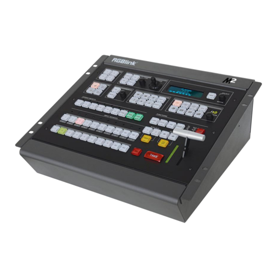
Now you choose input options, now you configure output operations, now control transitions from the T-bar, now apply layer masks, now do more. M2 redefines modern hands-on scaling and mixing for any environment. Totally modular and flexible in configuration, M2 is packed with standard features to impress and present with ease. -
Page 9: Rear Panel
Chapter 1: Your Product 1.2.1 Rear Panel Input Option Slots M2 provides 9 input option slots. A wide range of input connectors are available for user fitting, including DVI, VGA, HDMI, USB, CVBS, DP and SDI. DVI-I – DVI Each DVI module has one DVI-I input, which can be connected to signals with DVI port. - Page 10 Each SDI module has one SDI input and one SDI loop output port. The SDI input can be connected to signals from cameras and broadcasting processing device. It also can be connected to the next M2 or the device with SDI input. PGM Output HDMI-A –...
- Page 11 Chapter 1: Your Product AC 85-264V, 50/60HZ, MAX 45W, IEC-3...
-
Page 12: Front Panel
Chapter 1: Your Product 2 Front Panel Panel Instruction Layer adjustment buttons MASK buttons Layer selection buttons Transition buttons Layer effect buttons Functions buttons Multiview presets buttons Independent effects switching buttons Stored presets buttons OSD edit buttons Input source buttons Switchers Menu button and OLED display Layer Adjustment Buttons... - Page 13 Chapter 1: Your Product Screen parameters setting button. Press the button, its LED light turns on. User can choose between full size or screen size. FREEZE Freeze the image or video. Rotary Knob For dimension and position adjustment and confirmation. Press SCALE button and control the rotary knob to adjust the dimensions.
- Page 14 Chapter 1: Your Product Support 36 saving modes. LOAD Load saved views 1~36. PAGE For saving or loading, 6 pages in total, and 6 banks for each page. 1/2/3/4/5/6 These buttons can be used for numeric entry when SAVE or LOAD button is pressed. Input Source Buttons LED Indicator The button 1/2/3/4/5/6/7/8 is lit when the signal or background input is available.
- Page 15 Chapter 1: Your Product : Round : Crescent Left : Star : Diamond CUS1/CUS2 Mask custom button. Press any mask button, it will enter to the layer mask setting menus. Select the layer, and set the Mask & PIC Pos X and Y, or set Mask Pos X, Y of Mask or PIC separately. User can also load file from U Disk.
- Page 16 Chapter 1: Your Product Enable or disable the OSD function. Select “ON”, and user can delete the OSD, or load file from U Disk. BLACK The button is lit when BLACK function is enabled. BLACK is available for PGM channel only. Refer to Using Black Out.
-
Page 17: Dimension
Chapter 1: Your Product 1.2.3 Dimension... -
Page 18: Chapter 2 Installing Your Product
Chapter 2: Installing Your Product Chapter 2 Installing Your Product 2.1 Plugging in Signals Connect signals to the product (ensure all devices are powered off first). Tighten connector screws/locks where provided. 2.2 Plugging in Main Power Connect IEC cable to device and plug into wall socket. Turn on power at wall socket. 2.3 Turning on Your Product Turn on the power switch on the rear panel. - Page 19 Chapter 2: Installing Your Product PST Input : HDMI Output Format: 1920×1080@60 System Mode: Normal SN: 0019 Version: 1.59...
-
Page 20: Chapter 3 Using Your Product
Chapter 3 Using Your Product 3.1 Using the MENU Button Press the MENU button to display the main menu. Turn the rotary knob to navigate to the menu item required. If an item is selected, its background turns green. Press the knob to confirm the selection, and set the parameters or check information. -
Page 21: Understanding The Menu Structure
Chapter 3: Using Your Product 3.2 Understanding the MENU Structure The MENU structure is shown in the figure below:... -
Page 22: Using The Menu
Chapter 3: Using Your Product 3.3 Using the Menu Use the menu system for convenient and intuitive operation. M2 OLED display shows the menu items. The OLED display will show the default state when the menu is not in use, or the operation has timed out. -
Page 23: Input Menu
Chapter 3: Using Your Product ->Input >> Output >> Background >> Advance >> ->Language/语言 >> System >> Factory Reset >> There are 7 menu items in the main menu, and are displayed in 2 pages. Turn the rotary knob, and select any menu above, Press the rotary knob to confirm, the OLED display will show the submenu. -
Page 24: Output Menu
Chapter 3: Using Your Product 3.3.4 Output Menu ->Format 1920×1080@60 Custom Format >> System Mode >> Color Space/Sample/Bit >> ->External Sync >> Test Pattern >> Format There are 24 kinds of common resolutions. The special display or LED display application may require special resolution Custom Format settings to meet the requirement--refer to Custom the Output... -
Page 25: Background Menu
Chapter 3: Using Your Product Blue Range: 0~255. 3.3.5 Background Menu ->Background 1 File 1 Background 1 File 2 Background 1/2 Picture Picture File 1~14 can be selected. Load from U Disk Background 1/2 Whether to load file from U Disk. Delete Delete the selected file. - Page 26 Chapter 3: Using Your Product Set the vertical position of the LOGO. Delete Delete the selected LOGO. Load File From U Disk Load file from U Disk. ON/OFF Enable or disable the OSD function. Delete Delete the OSD. Load File From U Disk Load a file from U Disk.
-
Page 27: Language Menu
Chapter 3: Using Your Product Load a file from U Disk. Layer Select the layer. Blending Width Blending Set the blending width, the adjustment range is between 1~90. ON/OFF Enable or disable the Blending function. Layer Select the layer. Preset Select user, black background, green background, blue background, red background and white background. -
Page 28: System Menu
Chapter 3: Using Your Product 3.3.8 System Menu Version >> Ethernet >> T-BAR Calibration >> Key Board Test Fan Control >> ->Take Mode Swap Show the version of COM, PVW MCU, PVW FPGA, PST+PGM MCU, PST+PGM FPGA, Optional In 1 MCU, Optional In 1-1 Video, Optional In Version 1-2 Video, Optional In 1-3 Video, Optional In 2 MCU, Optional In 2-1 Video, Optional In 2-2 Video, Optional In 2-3 Video, Optional In 3 MCU,... -
Page 29: Pst Mode
Chapter 3: Using Your Product 3.4 PST Mode M2 can be connected to 2 preview displays with HDMI connectors, and the preview has the functions as below: 3.4.1 Signal Selection Press any button in Input Sources Area, for example, Press the button [5], the button is lit (yellow), and the signal in PGM monitor will be changed to signal 5. -
Page 30: Multiview Presets
Chapter 3: Using Your Product - Press the lit button in PGM area. The layers in PGM are also displayed in PST, synchronously; - Select layer [A] or [B]; - Press the FREEZE button, the selected layer is frozen in both PST and PGM displays, synchronously;... -
Page 31: Scale And Crop The Layer
Chapter 3: Using Your Product 3.4.6 Scale and Crop the Layer 1. Press any button of [A] to [D] in Layer Selection Area, the light flashes when the layer is selected. 2. Press the SCALE button in Layer Adjustment Area, and enter to the menus as follows: ->H Size 1920 V Size... - Page 32 Chapter 3: Using Your Product ->Blue Min Blue Max Layer: Select the target layer for DSK. Preset: Select user, black background, green background, blue background, red background or white background. Mode: Select Key In or Key Out. Alpha: The adjustment range is between 0~128. Red Min: The adjustment range is between 0~255.
-
Page 33: Blend Settings
Chapter 3: Using Your Product User In addition, User can select [User] in [Preset], which allows user to custom the color value by setting Red Min, Red Max, Green Min, Green Max, Blue Min and Blue Max values. Note: DSK applies to the Normal Mode only; ... -
Page 34: Mask Settings
Chapter 3: Using Your Product 3.4.9 Mask Settings 1. Press the MENU button, and enter to the menu items. 2. Turn the rotary knob, and select <Mask> option in <Advance>, Press the knob to confirm: ->Mask Heart Layer Layer 1 ON/OFF Set Mask&PIC Pos X together ->Set Mask&PIC Pos Y together... - Page 35 Chapter 3: Using Your Product Mask settings: The MASK shortcut button can be used as a shortcut button to enlarge the mask. For each MASK button, 6 dimensions are available. Press a shortcut button, press it again and the mask will be enlarged.
-
Page 36: Transition Settings
User can set the H position, V position, H size, V size of Mask and/or PIC. In addition, user can load custom masks by U Disk. Refer to the Custom EFFECT. 3.4.10 Transition Settings 1. Press the transition buttons in Transition Area, M2 has 14 kinds of wipe modes: : Iris Cross. ←+→ →+← : Iris Box. ←□→ →□←... -
Page 37: System Mode
Chapter 3: Using Your Product 3.5 System Mode 3.5.1 Normal (1) Press the MENU button and enter to the menu items. Turn the knob and select <OUTPUT>: Input >> ->Output >> Background >> Advance >> (2) Press the knob to confirm. Turn the knob, select <Normal> and press the knob to confirm: Format >>... - Page 38 Chapter 3: Using Your Product (3) Select <Normal Mode> and select <Start Quick Start Mode>: H Total 3840 V Total 1080 PGM 1 H Size 1920 ->Start Quick Start Mode >> (4) Select a layout: In the left mode, when <One Input Two Outputs> is selected, [A] is the background layer, [C] and [D] are the sublayers, [B] has no function.
- Page 39 Chapter 3: Using Your Product When <Two Inputs Two Outputs> is selected, [A] and [B] are background layers, [C] is the sublayer, and [D] has no function. 2. Overlayer (1) Press the MENU button and enter to the menu items. Turn the knob and select <Output>: Input >>...
- Page 40 Chapter 3: Using Your Product Overlayer width refers to the width of the overlapped part of two layers (two ports). (5) Select a background layout mode: In Layout 1, when <One Input Two Outputs> is selected, the overlapped part is as below: When <Two Inputs Two Outputs>...
-
Page 41: 4K2K
Chapter 3: Using Your Product In Layout 3, when <One Input Two Outputs> is selected, the overlapped part is as below: When <Two Inputs Two Outputs> is selected, the overlapped part is as below: 3.5.3 4K2K (1) Press the MENU button, enter to the main menu. Turn the knob and select <Output>: Input >>... -
Page 42: Matrix
Chapter 3: Using Your Product Normal >> 4K1K >> ->4K2K >> Matrix >> (3) Set the parameters: ->H Total 3840 V Total 2160 PGM1 H Size 1920 PGM1 V Size 1080 ->Set Note: 4P is available for 4K2K and Matrix only. ... -
Page 43: Switching Layers
Chapter 3: Using Your Product 3.6 Switching Layers User can use T-bar, CUT or TAKE to switch layers between PGM and PST. T-bar: Switch the PST layer PST to PGM; user can set the transition duration. The transition effect can be paused or played back by pushing T-bar. CUT: Quick seamless transition. - Page 44 Chapter 3: Using Your Product 切换后 If STAY is selected, the PST layer and PGM layer are the same even after pressing the CUT, TAKE button or using T-bar. The PST layer can be edited independently. After another switch, the PGM layer is the same with PST layer.
-
Page 45: Background Picture
Chapter 3: Using Your Product 3.7 Background Picture 3 sources can be used as the background picture of M2, they are input source, captured picture, and picture file loaded with U Disk. 3.7.1 Input Source User can use an input source as the background picture. For example, user can connect the device to a computer, and the current input can be used as the background. -
Page 46: Picture File Loaded With U Disk
Chapter 3: Using Your Product Background 1 Picture ->Picture File 1 Load from U Disk No U Disk Delete 3.7.3 Picture file loaded with U Disk The background picture can be a picture loaded with U Disk. See below: Before loading a picture: The maximum resolution is 1920×1080;... - Page 47 Insert the U Disk in the TF card or the USB control connector on the rear panel; Note: U Disk format: FAT32; The folder should be named M2 in the root directory, which contains IMAGE_1 and IMAGE_2; 2. By TF card Use card reader to write the images in the FT card (folder: IMAGE) in the PGM board.
- Page 48 Chapter 3: Using Your Product (3) Press the BK1 or BK2 in the PST area, and select Background 1→File 1 or Background 2→File 2. Save the settings. If the resolution does not meet the criteria. For example, the required resolution is 3800×1000. Follow the steps as below: (1) Press the MENU button, select <Output>: Input...
- Page 49 Chapter 3: Using Your Product (6) Press the BK1 or BK2 in the PST area, and select Background 1 File 1 or Background 2 File 2. Save the settings.
-
Page 50: Set The Output Resolution
Chapter 3: Using Your Product 3.8 Set the Output Resolution 3.8.1 Select the Output Resolution 1. Press the MENU button, and enter to the menu items, turn the rotary knob and select <Output>: Input >> ->Output >> Background >> Advance >>... - Page 51 Chapter 3: Using Your Product Format 1920×1080@60 ->Custom Format >> 4K1K >> Color Space/Sample/Bit >> ↓ ->H Active 1024 V Active Freq 4. Set H Active, V Active and Fred according to actual need, then select <Set> and set “Yes”, Press the rotary knob to confirm.
-
Page 52: Using Black Out
Black out description: One-key touch to black out the display M2 provides BLACK effect processing for PGM and PST, with instant BLACK effect. Operation is as below: Press the BLACK button, the button light is lit, and the PGM display is blacked out. -
Page 53: Saving Views
Chapter 3 : Using Your Product 3.10 Saving Views M2 provides 36 banks for saving or recording parameters. To save the current parameters and settings: 1. Press the SAVE button in Stored Presets Area, the SAVE and PAGE button lights are lit, and some of buttons 1~6 are lit and some are flashing. -
Page 54: Recall Saved Settings
Chapter 3: Using Your Product 3.11 Recall Saved Settings M2 provides 36 banks for saving or recording parameters. To recall saved settings: 1. Press the LOAD button in Stored Presets Area, the button lights of LOAD and PAGE are lit, and some of buttons 1~6 are lit and some are flashing. -
Page 55: Chapter 4 Ordering Codes
1 × SDI (with loop) 190-0001-09-1 CVBS In/Backup 1 × CVBS + CVBS BACKUP 190-0001-10-1 USB In/Backup 1 × USB + USB BACKUP 4.2.2 Accessories 980-0001-01-3 EXT3 Module (Support for 3 Input modules) 290-3072-01-0 Wings/Sides for M2 980-0006-01-0 LED Goose neck Lamp (Single) -
Page 56: Chapter 5 Support
Chapter 5 Support 5.1 Contact Us... -
Page 57: Chapter 6 Appendix
Chapter 6 Appendix 6.1 Specification DVI Input (DVI optional module) Interface Appearance Board Size 52(L)×19.5(W) (mm) Number of Inputs Connector Standard DVI-I socket Supported Resolution SMPTE: 625/25/50 PAL, 525/29.97/59.94 NTSC, 1080P50/59.94/60, 720p50/59.94/60 VESA: 800×600@60 | 1024×768@60 | 1280×1024@60 | 1600×1200@60 | 1920×1080@60 | 1920×1200@60 | 2048×1152@60 Signal Level TMDS pwl, single pixel input,165MHz bandwidth Format Standard... - Page 58 Format Standard DP1.0 CVBS Input (CVBS optional module) Interface Appearance Board Size 52(L)×19.5(W) (mm) Number of Inputs Connector Standard BNC Socket Supported Standards PAL/NTSC Signal Level 1Vpp±3db (0.7V Video+0.3v Sync) 75 ohm Multiplex 480i, 576i USB Input (USB optional module) Interface Appearance Board Size 52(L)×19.5(W) (mm)
- Page 59 Connector Standard BNC Socket Data Rate 2.97Gb/s, 2.97/1.001Gb/s, 1.485Gb/s, 1.485/1.001Gb/s and 270Mb/s Supported Standard SMPTE 425M - 3G Level A and Level B SMPTE 425M (3G Level A) 4:2:2: 1920×1080/60 (1:1) | 1920×1080/50 (1:1). SMPTE 425M (3G Level B DS1 and DS2) 4:2:2: 1920×1080/60 (2:1) | 1920×1080/50 (2:1) Supported Resolution SMPTE 296M (HD): 1280×720/50 (1:1) | 1280×720/50 (1:1)
- Page 60 Supported Resolution SMPTE: 625/25 PAL, 525/29.97 NTSC, 625/50p PAL, 525/59.94p NTSC, 720p50/59.94/60 | 1080i50/59.94/60 | 1080P50/59.94/60 VESA: 800×600@60 | 1024×768@60 | 1280×768@60 | 1280×1024@60 | 1600×1200@60 | 1920×1080@60 | 1920×1080@50 Format Standard HDMI 1.3 HDMI PST Output Number of outputs Connector HDMI standard type A interface Supported Resolution...
-
Page 61: Software Upgrade
Chapter 6: Appendix 6.2 Software Upgrade M2 supports software upgrade with USB and XTOOL, which compatible with Windows and Mac osX. The operations are as follows: 1. Preparation Upgrade tool installation package: XTOOLSoft_Setup 20161104PM.exe, upgrade cables. HL-340 USB-RS232 Serial Cable (Male) Note: HL-340 USB-RS232 serial cable applies to Windows system only. - Page 62 Chapter 6: Appendix 2.1.4 Select “Browse...” to select the XTOOL software install location: Note: User should get the rights in “Roles Management” when install the software to disk C for Windows 7 or Windows 10. (Install as Administrator) If user installs the XTOOL software on Windows 10, the installation should be operated under English directory.
- Page 63 Chapter 6: Appendix During installation, it will pop up the window of InstallShield Wizard for Virtual Com port: 2.1.5.1 If user installs the XTOOL software for the first time, click “Next”:...
- Page 64 Chapter 6: Appendix Then click “Install", as shown in the figure below: Click “Finish” and complete the installation, as shown in the figure below:...
- Page 65 Chapter 6: Appendix Then it will pop up the window of installation wizard for device driver, click “Next” to complete the installation. 2.1.5.2 If user have installed the XTOOL software before, click “Cancel”, and it will pop up the window as below: Click “Yes”...
- Page 66 2.2 Upgrade instruction Method 1: Upgrade with USB To avoid M2 skip the upgrade guide and upgrade directly, which may result in upgrading the wrong package, be sure there is No .PKG program, especially _UPDATE.PKG program before upgrade with USB.
- Page 67 2.2.3.6 After complete the upgrade, pull out the USB disk and restart M2. Method 2: Upgrade with serial cable 2.2.1.1 Connect M2 to PC via a serial cable (USB to DB9), and power on the M2. 2.2.1.2 Install CH-340 driver and get the SERIAL number: Right click the "Computer (My computer)"...
- Page 68 Chapter 6: Appendix 2.2.1.4 Upgrade M2 program After connection, the status will turn to green. Select the corresponding software program, and select all the different programs to upgrade by clicking “All” box, user can also click the program to upgrade manually. After selection, click “Upgrade” button as shown on the red box.
- Page 69 CORE_PGM and CORE_PVW version. Method 3: Upgrade with network cable (UDP) 2.2.2.1 Sets the IP addresses of M2 and the computer in the same network segment. Default IP address is 192.168.0.100 for M2. Right click “Network"→"Properties"→"Local Connection" →“Internet protocol version 4 “→”Set IP address” on the computer.
- Page 70 Chapter 6: Appendix Note: User can set the IP address of M2 according to the computer, and keep the IP address of M2 and computer in the same segment. 2.2.2.3 Upgrade M2 program After connection, the status will turn to green. Select the corresponding software program, and select all the different programs to upgrade by clicking “All”...
- Page 71 Chapter 6: Appendix 2.2.2.3.3 User should reboot the device after upgrade, otherwise, it will misidentify the CORE_PGM and CORE_PVW version.
-
Page 72: Using Xtool
Chapter 6: Appendix 6.3 Using XTOOL M2 equips the XTOOL, which is for upgrade, OSD Set, Effect Change, Logo and STILL settings. The files can be saved to the USB disk, and be loaded after custom the OSD, MASK, LOGO and STILL. -
Page 73: Custom Effect
Click TOOLBOX and select Effect Change. There are also rules to follow in saving a file: The file number should be 14-50 in order. Interruption is not permitted. The file should be named as M2\EFFECT. USB format: FAT 32 ... -
Page 74: Custom Logo
Select the BMP file and upload. Click TOOLBOX and select LOGO. There are rules to follow when saving the file: The file number should be 0~50 in order. Interruption is not permitted. The file should be named as M2\LOGO. The format of USB should be FAT 32. ... -
Page 75: Custom Still
Click TOOLBOX and select STILL. There are also rules to follow in saving a file: The file number should be 1-50 in order. Interruption is not permitted. The file should be named as M2\STILL. USB format: FAT 32 ... -
Page 76: Terms & Definitions
Chapter 6: Appendix 6.4 Terms & Definitions The following terms and definitions are used throughout this guide. “ASCII”: American Standard for Information Interchange. The standard code consisting of 7-bit coded characters (8 bits including parity check) used to exchange information between data processing systems, data communication systems, and associated equipment. - Page 77 Chapter 6: Appendix redder the light. Benchmark color temperature for the A/V industry include 5000°K, 6500°K, and 9000°K. “Contrast ratio”: The radio of the high light output level divided by the low light output level. In theory, the contrast radio of the television system should be at least 100:1, if not 300:1. In reality, there are several limitations.
- Page 78 Chapter 6: Appendix International Standards Organization working on algorithm standards that allow digital compression, storage and transmission of moving image information such as motion video, CD-quality audio, and control data at CD-ROM bandwidth. The MPEG algorithm provides inter-frame compression of video images and can have an effective compression rate of 100:1 to 200:1.
- Page 79 Chapter 6: Appendix signal for input to an image processor, transmission path or to improve its quality when presented on a particular display. “SDI”: Serial Digital Interface. The standard based on a 270 Mbps transfer rate. This is a 10-bit, scrambled, polarity independent interface with common scrambling for both component ITU-R 601 and composite digital video and four channels of (embedded) digital audio.
-
Page 80: Revision History
Chapter 6: Appendix 6.5 Revision History The table below lists the changes to the Video Processor User Manual. Format Time ECO# Description Principal V1.0 20180201 0000# Release Linger...
Need help?
Do you have a question about the M2 and is the answer not in the manual?
Questions and answers